S.R.Smith Splash! 300-0000 Guide

700-2000EU 07.29.2021
SPLASH!TM AQUATIC
PATIENT HOIST SERIES
OWNER’S MANUAL
&
MAINTENANCE PROCEDURES
S.R. SMITH, LLC
CORPORATE HEADQUARTERS
P.O. Box 400 • 1017 S.W. Berg Parkway
Canby, Oregon 97013 USA
Phone (503) 266 2231 • Fax (503) 266 4334
www.srsmith.com

2
TABLE OF CONTENTS
Splash! 300-0000/EU/K - Splash! Hi-Lo 350-0000/EU/K - Splash! Extended Reach 370-0000/EU/K -
Splash! Spa 375-0000/EU/K - Splash! ER Hi/Lo 385-0000/EU/K
INTENDED HOIST USER.............................................................................................................................2
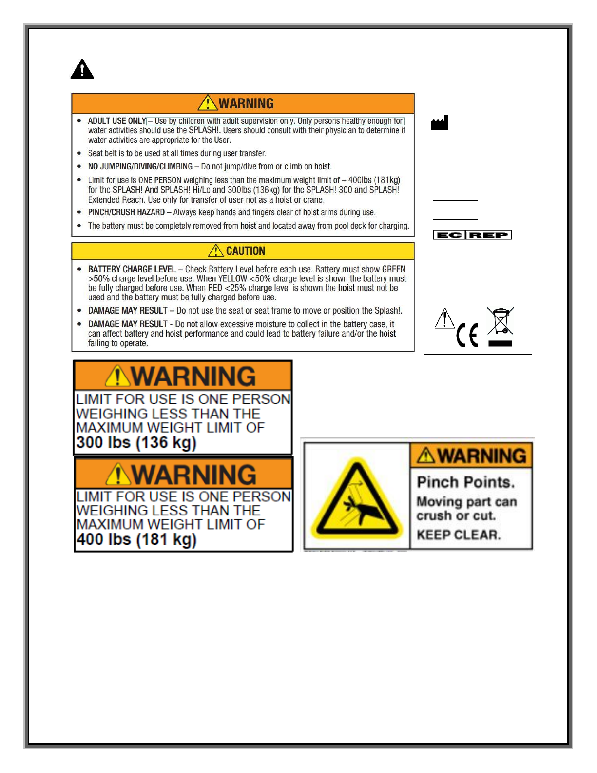
WARNINGS AND SAFETY SUMMARY .......................................................................................................3
PRODUCT OVERVIEW................................................................................................................................4
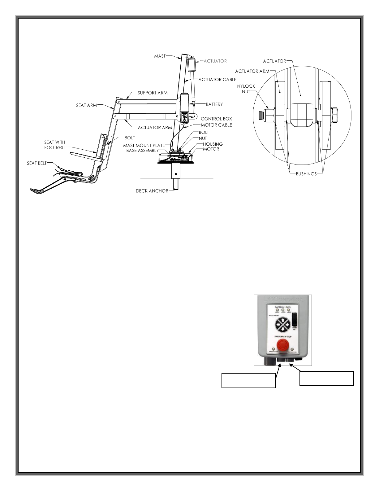
SPLASH! - PRODUCT COMPONENTS.......................................................................................................5
COMPONENT DESCRIPTION.....................................................................................................................5
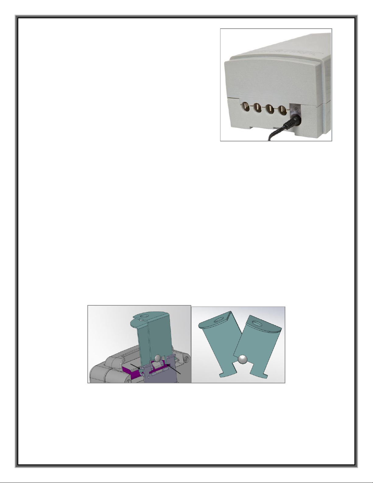
UNPACKING & ASSEMBLY INSTRUCTIONS.............................................................................................9
POOL DECK INSTALLATION FOR THE SPLASH! LOCKING ANCHOR .................................................11
USING THE Splash! Hoist ..........................................................................................................................12
TRANSFERRING........................................................................................................................................13
MAINTENANCE and CLEANSING.............................................................................................................14
TROUBLE SHOOTING...............................................................................................................................15
LONG-TERM STORAGE............................................................................................................................16
CUSTOMER CARE.....................................................................................................................................16
PRODUCT REGISTRATION & WARRANTY INFORMATION...................................................................17
SPECIFICATIONS ......................................................................................................................................18
1. Dimensions/Capacity.......................................................................................... 18
2. Actuator ........................................................................................................... 18
3. Motor ...............................................................................................................18
4. Battery.............................................................................................................18
5. Range of Motion ................................................................................................ 18
7. Materials and Finish ........................................................................................... 18
PARTS LIST (SPLASH!).............................................................................................................................19
PARTS LIST (SPLASH EXTENDED REACH)............................................................................................20
PARTS LIST (SPLASH EXTENDED REACH HI/LO or SPA).....................................................................21
Appendix - A................................................................................................................................................22
Appendix - B................................................................................................................................................22
Appendix - C ...............................................................................................................................................22
Read these instructions in their entirety before installation and use:
INTRODUCTION
Reading this document will help ensure safe operation and maintenance of the Splash! 300-0000/EU/K -
Splash! Hi-Lo 350-0000/EU/K - Splash! Extended Reach 370-0000/EU/K - Splash! Spa 375-0000/EU/K -
Splash! ER Hi/Lo 385-0000/EU/K.
INTENDED HOIST USER
All of S.R. Smith’s aquatic patient hoists have been designed to assist anyone who has problems entering
or exiting a swimming pool or spa - the only restriction is that the User does not exceed the weight limit of
the product (300 lb/136 kg to 400 lb/181 kg depending upon model). It is the responsibility of the hoist
Owner to ensure that the correct safety procedures have been put in place and a risk assessment carried
out. If a User is mentally challenged or has severe physical disabilities these issues must be taken into
account to determine the number of persons required to complete the transfer onto the seat and the
number of persons required to be in the water, ready to receive the User. The seat belt must be attached
to the seat and fully fastened and used during each transfer.
Our goal is to provide our customers with the most advanced and innovative designs offering exceptional
quality at affordable prices. All of our hoists meet the specifications set forth by the Access Board -
ADAAG 2004 (US only), Medical Device Directive, 93/42/EEC, RoHS2 Directive 2011/65/EU, EN
50581:2012 and ISO10535:2006 including repeating the lifting cycle of the hoist (lift) for a total of 11,000
cycles. The hoist system and AC powered battery charger complies with EN60601-1-2, 2007/03.
US Patent No. 5,790,995 Splash! and the Splash! Logo and LiftOperator are registered trademarks of S.R. Smith, LLC.

3
WARNINGS AND SAFETY SUMMARY
DANGER –FAILURE TO FOLLOW THESE WARNINGS, INSTRUCTIONS AND THE OWNER’S MANUAL MAY
RESULT IN SEROUS INJURY OR DEATH
Model / Product No.______
Product Name ___________
S.R. Smith, LLC
PO Box 400
1017 SW Berg Parkway
Canby, Oregon 97013 USA
Phone: 503-266-2231
Fax: 503-266-4334
www.srsmith.com
Assembled in the USA
SN S
QNET BV
Kantstraat 19
NL-5076 NP Haaren
The Netherlands
qnet@ce-
authorizedrepresentative.eu
24 VDC

4
DECK PROFILE SHEET
Aquatic patient hoists are application specific. A completed Deck Profile Sheet helps to ensure the hoist
model will work for the intended application. S.R. Smith reviews all submitted Deck Profile Sheets as a
service to our customers, free of charge. Before installing the pool hoist, the installer must review and
confirm the information provided on the Deck Profile Sheet. If the description of the application does not
match the installation site, a new Deck Profile Sheet must be completed and submitted to S.R. Smith.
To complete the Deck Profile Sheet online, visit www.srsmith.com/liftprofile, contact Customer Service at
(800) 824-4387 or email cu[email protected]m.
PRODUCT OVERVIEW
S.R. Smith’s Splash! aquatic hoists are designed for safety, as well as consistent, reliable operation. It is
essential to follow all instructions in this owner’s manual, as well as all warning labels located on the
product to ensure safe operation, proper performance and to avoid injury.
The Splash! Aquatic Patient Hoist series are a semi-portable hoist system designed so that individuals
with disabilities and mobility impairments can have universal access to any type of swimming pool or spa.
Powered by a 24 volt rechargeable battery, the lifting motion is provided by a screw driven electronic
actuator and an electronic gear motor provides the turning motion. The Splash! is available in a Spa
version for use with above-ground pools and spas; a Hi/Lo version for facilities with both above-ground
and ground level pools and spas; and an Extended Reach version for facilities with longer deck to water
requirements. Although the Splash! must be operated from a stationary deck anchor it can be transported
using the Splash! Caddy. The Caddy is designed to facilitate lifting the Splash! out of the deck anchor and
also serves as a storage rack when the hoist is not needed. The maximum lift capacity for Splash! /
Splash! Hi-Lo / Splash! Spa models is 400 lb/181 kg. The Splash! Extended Reach is 300 lb/136 kg. Only
persons healthy enough for water activities should use the Splash!. Users should consult with their
physician to determine if water activities are appropriate for the User.

5
SPLASH! - PRODUCT COMPONENTS
COMPONENT DESCRIPTION
The Base Assembly is made up of several components described below:
Base Assembly - Mounts to the pool deck or concrete boat dock.
Base Insert Stem - Slides into the anchor sleeve that is installed on the pool deck or dock.
Housing - ABS plastic cover shields base assembly components from weather. Must be in place prior to
installing the mast assembly.
Attachment Cover - Slides down over housing to cover hardware (bolts and washers).
LiftOperator Control Box - The unit controls all hoist operations identical
to the user hand set. Three cables connect to the bottom of the Control
Box to enable operation of the hoist. The largest connector is for the hand
control. Connector # 1 is for the motor cable (red stripe). Connector # 2
is for the actuator cable (green stripe).
Touchpad Control –
The touchpad control arrow keys can be used in the event that the hand control is out of reach or
fails. Simply press and hold the arrow for the desired action for one movement at a time –Up,
Down, Left, Right Releasing the Arrow stops movement.
CONNECTOR 1
(MOTOR CABLE)
CONNECTOR 2
(ACTUATOR CABLE)

6
Battery Level LED Indicators –
The Battery Level LED Indicators show battery charge levels. The LED’s will illuminate when
either the touchpad control or the hand control is activated and will stay lit for 10 seconds. At
greater than 50% the LED glows Green, at less than 50% the LED glows Amber, and less than
25% the LED glows red and indicates the battery requires charging. If the less than 25% LED
glows red, do not operate the hoist. Remove the battery and fully charge before use.
Service Required LED –
The Service Required LED will illuminate when the battery pack has been removed/replaced 120
times - approximately once every 4 months. This indicates that required maintenance for the hoist
must be completed. Please see the maintenance section of the Hoist Owner’s Manual for the
requirements. The Service Required LED can be reset by inserting a standard FAT-formatted
USB mass storage device (not included) into the USB Port on the bottom of the controller. When
the service light is illuminated the hoist must not be used until required maintenance is
performed.
Emergency Stop Button –
In the event of an emergency, or if you need to stop hoist movement
immediately, pressing the Emergency Stop Button (red button on the control)
will stop all hoist movement. At the same time an audible alert will sound for
10 sec. then pause for 5 sec. and then the sequence will repeat until the
button is reset by turning it in the direction of the arrows on the button
(clockwise). The Emergency Alert LED will also flash Red when the button is
pressed and will remain flashing until the button is reset.
The Emergency Alert (audible and LED) can be activated by pressing any
two buttons on the hand control at the same time (provided with the hoist).
This will stop all hoist movement and activate the audible alert and the Red
LED will flash. Once both buttons are released, the hoist will return to normal
operation and the emergency audible alert will silence.
USB Port –
The LiftOperator control contains a USB port that is used to download the performance log of the
hoist. Using any standard FAT file formatted USB memory stick (widely available through retail
outlets) insert the stick into the slot on the bottom of the control on the far right hand side. Press
any of the touchpad control arrows; all three of the Battery Level LED’s will flash. During
downloading the Green greater than 50% Battery Level LED will flash. If the unit has a problem
downloading the performance log the Red less than 25% LED will flash. Remove the USB from
the port and re-insert it. If the Red 25% LED flashes again, confirm that the USB you are using is
FAT file formatted. The information from the USB can be downloaded to a PC for review and/or
copied to a spread sheet. The performance log will retain approximately 7,600 events. Once the
file is full it will remove the oldest event and replace with the newest.
After the summary data, the events are shown with the oldest first. The first column is the time in
seconds from that last event. The second column is the text describing the event. The third
column is duration of the activity noted in seconds.
4-Button Hand Control

7
An example of a short log file:
Activity Description
dev_id_upper,0 Programing data
dev_id_lower,1 Programing data
fw_rev,90 Firmware rev.
batt_volt_float,24929 Non-loaded battery voltage in millivolts
batt_volt_load,21487 Loaded battery voltage in millivolts
batt_capacity,99 Estimated battery capacity in %
charge_starts,8 Number of times charging was attempted
charge_completes,1 Number of times charging was finished successfully
0,power_on,1 Connecting Battery Pack
2,alert_pressed, Emergency Button pressed
3,alert_released, Emergency Button released
8,lift_up,2 Hoist movement - up
5,lift_down,2 Hoist movement - down
11,lift_up,2
4,turn_left,2 Hoist movement - turn left
3,turn_right,1 Hoist movement - turn right
3,log_write, USB File Download
Battery Pack - The battery pack is located on top of the Control Box and is removable.
To remove - pull the battery pack away from the mounting plate so that the latch on the battery
pack clears the side tabs on the mounting plate - then lift the battery pack up and away from the
Control Box.
To replace - align the battery pack with the mounting plate so that the latch will drop over the
center tab and that the bottom of the battery pack will fit in the recessed area on top of the Control
Box. Lower the battery pack in place so that the latch is fully captured by the mounting plate and
the battery pack drops fully seated onto the Control Box.
The battery must be completely removed from the hoist and located away from the pool deck for
charging.

8
The battery pack should be charged daily. Do not allow battery
to fully discharge, as it will shorten battery life.
The battery pack has an LED indicator near the plug-in-port. It
will glow Red when first plugged into the transformer. If the
LED remains Red this indicates the battery pack needs
charging. When fully charged the LED will glow Green. If the
battery is fully charged and is plugged into the transformer the
LED will glow Red for approximately 10 sec. then glow Green.
If the LED flashes Red when plugged in this indicates a fault
with the battery and indicates the battery pack should be
replaced. All batteries are inspected prior to shipment. See
warranty policy regarding battery replacement for problems
after sale. Batteries have a normal lifespan of between 2-3
years, depending on use and care. A fully charged battery will
provide approximately 30 to 40-lifting cycles, depending on the
weight of the users. Prior to use the battery charge level should
be checked by observing the LED indicator above the charger plug to ensure sufficient charge level. The
charger must be connected to the battery to view the LED.
It is not necessary to fully discharge the battery prior to charging. Battery should be charged daily and
cannot be overcharged. It takes up to twelve hours to fully charge depending upon battery usage. Do not
allow battery to fully discharge, as it will shorten battery life.
Do not drop the battery, as it could cause the unit to fail. If the battery case is cracked do not use and
replace the battery. During temperature extremes beyond the range of 41 F (5 C) to 104 F (40 C) remove
battery and place in a controlled environment or battery life may be shortened.
Battery Disposal - The batteries located inside the battery pack are recyclable and shall be disposed of
in accordance with applicable local, state/provincial or federal/national regulations.
Locking Plate Assembly - The battery pack can be secured to the mounting plate using the provided
lock plate assembly. To install open the lock plate so that the bottom tabs are moved close to one another
to allow the lock plate to be inserted into the slots on the mounting plate secured to the hoist. Close the
lock plate assembly so that the tabs are captured by the slots. Insert a padlock (not provided) through the
holes on the lock plate assembly to secure it.
Hand Control - The four button unit controls all hoist movements. The arrows indicate direction of
movement. Control is fully waterproof and meets IP67 standards.

9
Mast - This vertical piece is bolted to the base assembly.
Actuator - Attached to mast, this part powers the up and down movements
of the hoist.
Rotation Motor Assembly –Consists of mounting plate, 24-volt motor and small
gear.
Hub Assembly –Consists of hub, bearings, shaft, large gear and mast mounting
plate.
Horizontal Support Arms - These two support arms connect the mast to the seat
support arm. The longer horizontal support arm (actuator arm) connects to the
actuator and initiates the lifting movements.
Seat Support Arm - Connects seat to the horizontal support arms.
Seating System - The seat is manufactured from roto-molded plastic with a stainless steel frame. The
seat comes standard with a seatbelt.
The seatbelt must be used during each use. It is recommended that the seat be rinsed off with fresh
water between each use and cleansed daily with a disinfectant solution of 1:100 dilution of household
bleach to fresh water and then rinsed with fresh water. In the event of a contamination incident such as
patient/user excreta - cleanse seat and seatbelt immediately with the above disinfectant solution. Do not
use seatbelt if it is damaged or becomes worn.
Armrests are included as a standard item on all S.R. Smith hoists. The armrests are designed so they can
be rotated up out of the way during transfer.
This hoist seat assembly is designed to be used exclusively with S.R. Smith aquatic access hoists.
UNPACKING & ASSEMBLY INSTRUCTIONS
REFER TO THE DIAGRAM (page 19) FOR PARTS IDENTIFICATION.
READ THESE INSTRUCTIONS IN THEIR ENTIRETY BEFORE UNCRATING THE SPLASH!
Prior to opening the pallet, inspect the external condition for any visible damage. It is important
that any damage be noted on the Bill of Lading. Immediately notify S.R. Smith or your Authorized
Reseller of missing or damaged parts.
Ensure mounting anchor has been installed in the correct location in the pool deck for proper
hoist operation. It is recommended that the anchor be installed by a person familiar with installing
pool deck equipment.
The Splash! is shipped on a covered pallet and is VERY HEAVY. You will need the following tools for
unpacking and assembly:
•3/4” or 19mm socket wrench
•9/16” or 14mm socket and 9/16” or 14mm wrench
•small flat blade screwdriver
•knife or cutters to cut shrink-wrap/bands
Unpacking & Assembly Procedure for the Splash!
1. Cut open enclosure bag around the pallet - carefully remove plastic.
4-Button Hand Control

10
2. Cut bands around components.
3. Remove the accessory box and seat assembly. DO NOT remove housing cover. It is attached to
the base.
4. Lift the base unit and insert it into the deck anchor using the metal handle located on the top of the
Housing. DO NOT LIFT BASE UNIT USING PLASTIC HOUSING. Make sure that the tab located
on the side of the Splash! base is aligned with the threaded tab in the LiftLock2 deck anchor. Use
the 3/8” hex bolt, lock washer, and flat washer to secure the Splash! base to the LiftLock2 anchor.
If you are installing the hoist in a pre-existing anchor that does not include a threaded tab, contact
S.R. Smith for information on a retrofit kit. Once the hoist base has been placed into the deck
anchor, unfasten the nuts and remove and discard the metal handle.
5. Position the mast assembly onto the housing cover by lowering the mast base onto the studs
protruding from the housing. Attach the washers and lock nuts onto the studs and fully tighten
using a 3/4” or 19mm socket wrench. Slide attachment cover to cover the bolts.
6. Remove plastic from mast assembly. Remove 3/8” (10mm) bolt and nut from actuator arm end.
Following the illustration - attach actuator end to end of actuator arm using the same 3/8” (10mm)
bolt and nut. Fully tighten bolt and nut using 9/16” (14mm) socket and wrench.
Deck to Water Edge
LiftLock2 Anchor
Tab
Splash Base Tab

11
7. Remove twist tie and uncoil cable on top of housing. Insert plug (with red stripe) into connector #1
on Control Box. Insert cable into wire chase on front of mast, then push to close/lock wire chase.
Make sure plug is secure.
8. Remove twist-tie and uncoil actuator cable at bottom of mast.
9. Insert actuator cable plug (green stripe with the “o” ring) into connector #2 on the Control Box.
Make sure plug is secure.
10. Remove and unwrap hand control from accessory carton. Insert plug into large connector on the
Control Box and hang hand control on handle. Make sure plug is secure.
11. Attach battery to Control Box. To remove battery, pull slightly away from mounting plate and lift
battery pack off of the Control Box.
12. Check up and down controls for proper operation - both touch pad and hand controls.
13. Check side to side controls for proper operation –both touch pad and hand controls.
14. Check Emergency Stop button for operation/activation of internal sounder.
15. Remove the battery and charge it fully before users begin to use the hoist.
16. Attach seat assembly with bolt and thumbnut in appropriate hole. For storage, seat can be
attached facing inward for less space.
17. Attach footrest to seat with bolts and thumbnuts.
POOL DECK INSTALLATION FOR THE SPLASH! LOCKING
ANCHOR
Ensure Locking Anchor has been installed in the correct location in the pool deck for proper hoist
operation. It is recommended that the anchor be installed by a person familiar with installing pool
deck equipment.

12
The optimal mounting distance for the deck anchor is between 12”/30.5 cm to 18”/46 cm from the edge of
the pool. Please call S.R.Smith with any questions concerning deck anchor placement or if the SPLASH
will work in your installation.
INSTALLING AN ANCHOR IN A CONCRETE DECK
The proper installation of the anchor depends on the construction and condition of the deck. If the deck
meets the thickness and re-enforcing requirements shown in Appendix A then the anchor can be installed
according to the instructions outlined in Appendix A.
If the existing deck does not meet the requirements outlined in Appendix A then the anchor can be
installed per the instructions in Appendix B or C, or you can consult with an engineering professional.
The deck anchor reaction loads can be found in the Specification Section of this manual.
Properly bond the anchor socket using the attached bonding screw per local codes
USING THE Splash! Hoist
Obey all User Instructions listed in the Owners Manual whenever using hoist. Obey all Caution,
Warning, Operating Instruction(s) and Labels located on the hoist whenever using. It is the
responsibility of the hoist Owner to ensure that the correct safety procedures have been put in
place and a risk assessment carried out. If a User is mentally challenged or has severe physical
disabilities these issues must be taken into account to determine the number of persons required
to complete the transfer onto the seat and the number of persons required to be in the water,
ready to receive the User. If the Splash! will be used by a disabled person living on their own, a
communication device should be installed in the area of use to call for assistance in the event of
an emergency. Only persons healthy enough for water activities should use the Splash!. Users
should consult with their physician to determine if water activities are appropriate for the User.
Keep fingers and hands clear of hoist arms during use.
DW EDGE
Locking Deck Anchor
(Install the anchor so the locking tab is perpendicular and
furthest away from the Deck to Water (DW) edge)

13
Splash! Transferring Diagram
TRANSFERRING
Once the unit is positioned for use, use the following procedure to transfer to the seat and into the water.
Only persons healthy enough for water activities should use the Splash!. Users should consult with their
physician to determine if water activities are appropriate for the User:
•Keep fingers and hands clear of hoist arms during use.
•Rotate the seat to either side of hoist for best transfer position.
•Raise or lower the seat to proper transfer height.
•Transfer onto the seat, ensuring that the user’s weight is centered on seat. Armrests can be
rotated up if necessary. If user has a wheelchair, keep the wheelchair close by for easy retrieval.
•Fasten Seat Belt - thread loose end of belt strap through buckle - pull tight - to close - press latch
down on belt material.
•Raise seat to allow enough leg room for rotation.
•Rotate seat to the 12:00 position, over the water.
•Lower the seat into the pool. The waterproof hand control can remain connected to seat if
swimmer is operating hoist.
•Unfasten Seat Belt - grasp latch and lift up, pull loose end from latch.
•When finished, return to the seat, ensuring user’s weight is centered on seat.
•Fasten Seat Belt.
•Raise seat to allow enough leg room for rotation.
•Rotate seat to original transfer position.
•Raise or lower seat to proper transfer height.
•Unfasten Seat Belt.
•Transfer off of the seat.

14
IN CASE OF HAND CONTROL FAILURE
Lifting failure - In the event of a lifting failure, there are control buttons built into the control box. Press
the appropriate up or down/left or right button located on the front panel of the control box.
If the Splash! will be used by a disabled person living on their own, a communication device
should be installed in the area of use to call for assistance in the event of an emergency.
Turning failure - If the hoist will not turn electronically, unplug the motor cord from the controller (see
pg.6), then manually rotate the mast.
If the Splash! will be used by a disabled person living on their own, a communication device
should be installed in the area of use to call for assistance in the event of an emergency.
STANDARD ACCESSORIES/OPTIONAL ACCESSORIES
The following items are included with all aquatic patient hoist models:
•Seat Belt Assembly - Nylon water-resistant belt for added security.
•Battery/Charger –24-volt rechargeable battery.
•Console/Battery Cover –Protects batter and control unit from exposure to UV and moisture
(Tan).
Optional accessories may be purchased for your Splash! hoist through your Authorized Reseller. The
following accessories are available:
Total Cover - # 920-5000: Made of weather resistant nylon material to keep unit protected from elements
when not in use.
Spine Board Attachment - # 500-1000: Can be used to convert hoist for use with any standard spine
board. (Spine Board not included)
Splash! Caddy - # 400-0000 - Facilitates handling, transporting and storing the Splash! Simplifies both
insertion and removal from deck anchor and can be used as a storage rack when hoist is not in use.
Anchor & Cap –# 300-6600L –LiftLock2 deck anchor measures 2.875”/ 73 mm OD, 2.75” / 70 mm ID.
Includes cap and bonding screw.
MAINTENANCE and CLEANSING
Minimal maintenance will prolong the life of your hoist. Keep all electronic components clean and dry.
Excessive moisture collection can affect battery and hoist performance and could lead to battery failure
and/or the hoist failing to operate. If the hoist is used outdoors, an optional full cover is available and
recommended.
Owners of hoist should be aware of any applicable local, state/provincial or federal/national regulations
regarding the inspection and or testing of hoists.

15
The following schedule shall be performed to insure proper operation with the Daily items
performed before each use:
Maintenance Performed
Daily
Weekly
Monthly
Check battery level before each use / Charge battery daily
Wipe Control Box and battery connection with a clean dry rag
Examine hoist for any damage, loose or missing hardware
Test for normal operation
Spray gear assembly with a heavy-duty rust inhibitor/lubricant
such as LPS 3 - Heavy-Duty Inhibitor
Make sure all cable connections are properly secured
Inspect hoist frame, mast, support arm and seat assembly for
rust
Cleansing Performed –after each use
Rinse seat and seatbelt with fresh water between each use -
Cleanse seat and seatbelt with a disinfectant solution of 1:100
dilution of household bleach to fresh water and then rinse with
fresh water and dry entire hoist daily. In the event of a
contamination incident such patient/user excreta - cleanse seat
and seatbelt immediately with the disinfectant solution*
Cleanse all battery connections with a nylon scouring pad
Cleanse all metallic surfaces with a cleaner wax to maintain the
finish of the hoist
* When using the disinfection solution avoid direct contact with the skin and eyes. In the event of
a contamination incident - immerse the seat belt in the disinfection solution for 10 min. and then
rinse thoroughly with fresh water.
TROUBLE SHOOTING
Be sure the battery is fully charged before troubleshooting.
Hoist does not rotate
Does hoist raise or lower?
Yes.
1. Check connection to Control Box. Be sure plug is pushed in all the way.
2. Check hand control connection to Control Box for damaged pins.
3. Check connections on terminal block located on frame for loose wires.
4. Check connection cable for damage.
5. Try operating the hoist using the control buttons on the front panel of the controller. If
the hoist rotates when using the buttons on the control box, the hand control is likely the
problem.
6. If the hoist does not rotate when using the buttons on the control box, reverse the
motor cables as follows: Locate the area on the Control Box where the cables are
attached. Swap the actuator cable from connector #2 with the 24v motor cable from
connector #1. Activate the up and down buttons on the hand control. If hoist rotates, the
problem is likely the hand control. If hoist does not rotate, the problem is likely the 24v
motor.
7. Contact your Authorized Reseller or S.R. Smith for replacement information.
Does hoist raise or lower?
No.
1. Check battery charge level.
2. Check battery connection.
3. Use another fully charged battery. If hoist continues to not function, replace the
Control Box.

16
Hoist does not Raise or Lower
Does hoist rotate?
Yes.
1. Check connection to Control Box. Be sure plug is pushed in all the way.
2. Check hand control connection to Control Box for damaged pins.
3. Check connection cable for damage.
4. Activate the up and down buttons on the front panel of the control box. If hoist raises
and lowers, the problem is likely the hand control.
5. If the hoist does not raise and lower when using the buttons on the control box,
reverse the cables as follows: Locate the area on the Control Box where the cables
are attached. Swap the actuator cable from the connector #2 and the 24v motor
cable from connector #1. Activate the left and right buttons on the hand control. If the
hoist raises and lowers, the problem is likely the hand control. If the hoist does not
raise and lower, the problem is likely the Actuator.
6. Contact your Authorized Reseller or S.R. Smith for component replacement
information.
Does hoist rotate?
No.
1. Check battery charge level.
2. Check battery connection.
3. Use another fully charged battery. If hoist does not function, replace the Control Box.
LONG-TERM STORAGE
When storing the hoist for an extended period of time:
•Wash seat with disinfectant solution and then rinse with fresh water and dry entire hoist
•Spray gear assembly with a heavy-duty rust inhibitor and lubricant such as LPS 3
•Keep the battery on the charger in a dry temperature controlled area
•Cover unit and store in a dry location away from pool chemicals
CUSTOMER CARE
Customers are encouraged to read and obey all of the user instructions listed in this manual whenever
using the hoist. Comply with all Caution, Warning, Operating Instructions and Labels located on the hoist.
If the hoist will be used by a disabled person independently, a communication device should be available
in the area in the event of an emergency. Only persons healthy enough for water activities should use the
hoist. Users should consult with their physician to determine if water activities are appropriate for their
condition. Keep fingers and hands clear of hoist arms or pinch points during use.
In the event of a malfunction of the hoist or serious incident to a user, contact SR Smith at 1-800-824-

17
information regarding Authorized Resellers worldwide visit www.srsmith.com
PRODUCT REGISTRATION & WARRANTY INFORMATION
Register your hoist at srsmith.com. Product registration ensures you receive timely information about
product updates and in the event of a warranty issue, helps us process claims more efficiently.
The S.R. Smith warranty becomes effective on the date of manufacture.
To initiate a warranty replacement, Please follow the process outlined below.
1. Take photos of the damaged product.
a) The photo must include the entire unit
b) Also include one photo or more of the damaged area.
2. Write down or take a photos of the serial # sticker from the product.
S.R. Smith provides a serial # for every pool hoist we produce. The sticker with the serial number
can be found at the bottom of the mast near the base.
3. Attach the photos and the serial # to a written request for replacement under the S.R.
Smith warranty. Please include the following information:
a) Product name and description.
b) Date of purchase and/or date of installation.
c) Description of damage.
d) Shipping address with a contact name and phone number.
4. Send photos, serial # sticker and your written request by email or mail to
customercare@srsmith.com or:
S.R. Smith, LLC
PO Box 400
1017 SW Berg Pkwy
Canby, OR 97013
Attn: Warranty Specialist
**NOTE: Missing information will result in a processing delay and possibly denial of your claim.
Should you have any questions regarding this process, please contact
S.R. Smith's Warranty specialist at 800.824.4387 or 503.266.2231 or email customerc[email protected]om

18
SPECIFICATIONS
1. Dimensions/Capacity
Overall Height 66.25”/168cm
Base Dimensions 19.25”/49cm Dia.
Total Weight 160 lb/72.5 kg
Overall Length (footprint) 90”/229cm (fully extended, with footrest)
68.75”/176cm (fully retracted, with footrest)
40”/102cm (in stored position, no footrest)
Power 24V DC
Battery Life 30 cycles (approx.)
Lifting Capacity 400 lb/181 kg - 300 lb/136 kg (Splash! Extended Reach)
Anchor Reaction Load
Vertical 525 lb/238 kg (Splash!/Hi/Lo) 430 lb/195 kg (Splash! ER)
Torque 1820 ft lb/2468 NM (Splash!/Hi/Lo)
1875 ft lb/2542 NM (Splash! ER)
Seat Width 23”/58.5cm
2. Actuator
Lifting Screw Type Mechanical Actuator
Max. Thrust 1680 lb/7472N
Voltage 24V DC
Max. Amp 9
Max. Speed 0.59 inch/sec./1.49cm/sec.
3. Motor
Rotation 24 VDC, 13 RPM
Gearing Ratio 9:1
4. Battery
Power 24 VDC, IP65 Gel Lead Acid
Temperature Range 41 F (5 C) to 104 F (40 C)
5. Range of Motion
Lifting Variable to configure to each pool. 44”- 58”/112cm –147cm total
travel from highest to lowest point w/standard actuator.
Seat Depth 18-20”/46cm –51cm below water line.
Rotation 359º
6. Noise Noise level below 50 dB (A), measured according
to DS/EN ISO 3746”
7. Materials and Finish
Frame Powder Coated Stainless Steel
Housing Vacuum Formed ABS Plastic
Arms Powder Coated Aluminum
Mast Powder Coated Stainless Steel
Seat Assembly Seat: Roto-Molded Plastic
Frame: Powder Coated Stainless Steel
Covers Urethane coated nylon

19
PARTS LIST (SPLASH!)
Item #
Part #
Description
1
100-5000A
LA34 Actuator
2
1001499
4 Button Control Unit
4
1001495
Battery Pack
5
1001530
Battery Charger (not shown)
6
100-4000A
Hand Control
7
120-1100
24v Motor
8
135-1000
Hub Assembly
9
120-1000
Motor Mount Assembly
10
800-5065
Small Gear
11
150-1100A
Mast Assembly
12
150-1200A
Actuator Arm Assembly
13
150-1300A
Support Arm Assembly
14
150-1400A
Seat Arm
15
160-8000A
Seat Assembly
16
160-2300A
Foot Rest
17
300-1100
Splash! Base Assembly
18
300-5200A
Mast Collar
19
300-5000A
Splash! Housing
20
900-1000
Seat Belt
21
910-1000T
Console/Battery Cover (Tan) (not shown)
22
940-1100
Splash! Mast Cover (Optional Accessory, not shown)
23
900-6000
Stability Strap (Optional Accessory, Not Shown)
24
970-5000
Seat Cover (Optional Accessory, Not Shown)

20
PARTS LIST (SPLASH EXTENDED REACH)
Item #
Part #
Description
1
100-5000A
LA34 Actuator
2
1001499
4 Button Control Unit
4
1001495
Battery Pack
5
1001530
Battery Charger (not shown)
6
100-4000A
Hand Control
7
120-1100
24v M18otor
8
135-1000
Hub Assembly
9
120-1000
Motor Mount Assembly
10
800-5065
Small Gear
11
160-8000A
Seat Assembly
12
160-2300A
Foot Rest
13
300-1100
Splash! Base Assembly
14
300-5200A
Mast Collar
15
300-5000A
Splash! Housing
16
325-1200A
ER Actuator Arm Assembly
17
325-1300A
ER Tension Arm Assembly
18
150-1400A
ER Seat Arm Assembly
19
150-1100A
ER Mast Assembly
20
900-1000
Seat Belt
21
910-1000T
Console/Battery Cover (Tan) (not shown)
22
940-1100
Splash! Mast Cover (Optional Accessory, not shown)
23
900-6000
Stability Strap (Optional Accessory, Not Shown)
24
970-5000
Seat Cover (Optional Accessory, Not Shown)
This manual suits for next models
4
Table of contents
Other S.R.Smith Lifting System manuals
Popular Lifting System manuals by other brands

HIRD GLASS
HIRD GLASS WINLET 350 Operator's manual

SINOLIFT
SINOLIFT ETM Series operating manual

BYD
BYD ECB16 Operator's manual

Granberg
Granberg Baselift 6300H installation instructions

REID LIFTING
REID LIFTING PORTA-BASE Assembly & Operation guide

REID LIFTING
REID LIFTING PGRS20 Assembly & Operation guide

Tommy Gate
Tommy Gate 650 Series Owner's/operator's manual

Faraone
Faraone ELEVAH 40 MOVE PICKING Use and maintenance instructions

Audipack
Audipack ML-350 Series Mounting instructions

Vestil
Vestil AHA-KIT instruction manual

Terex
Terex Genie SX -180 Service and repair manual

Future Automation
Future Automation UBLS Application notes