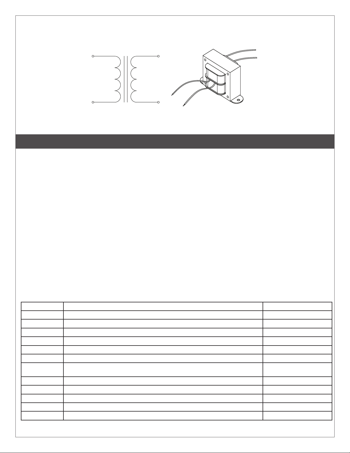
Transformer
Refer to the graphic below to wire the transformer.
Black
Black
Red
Red
Primary
(120V AC)
Secondary
(24V AC)
Transformer Schematic
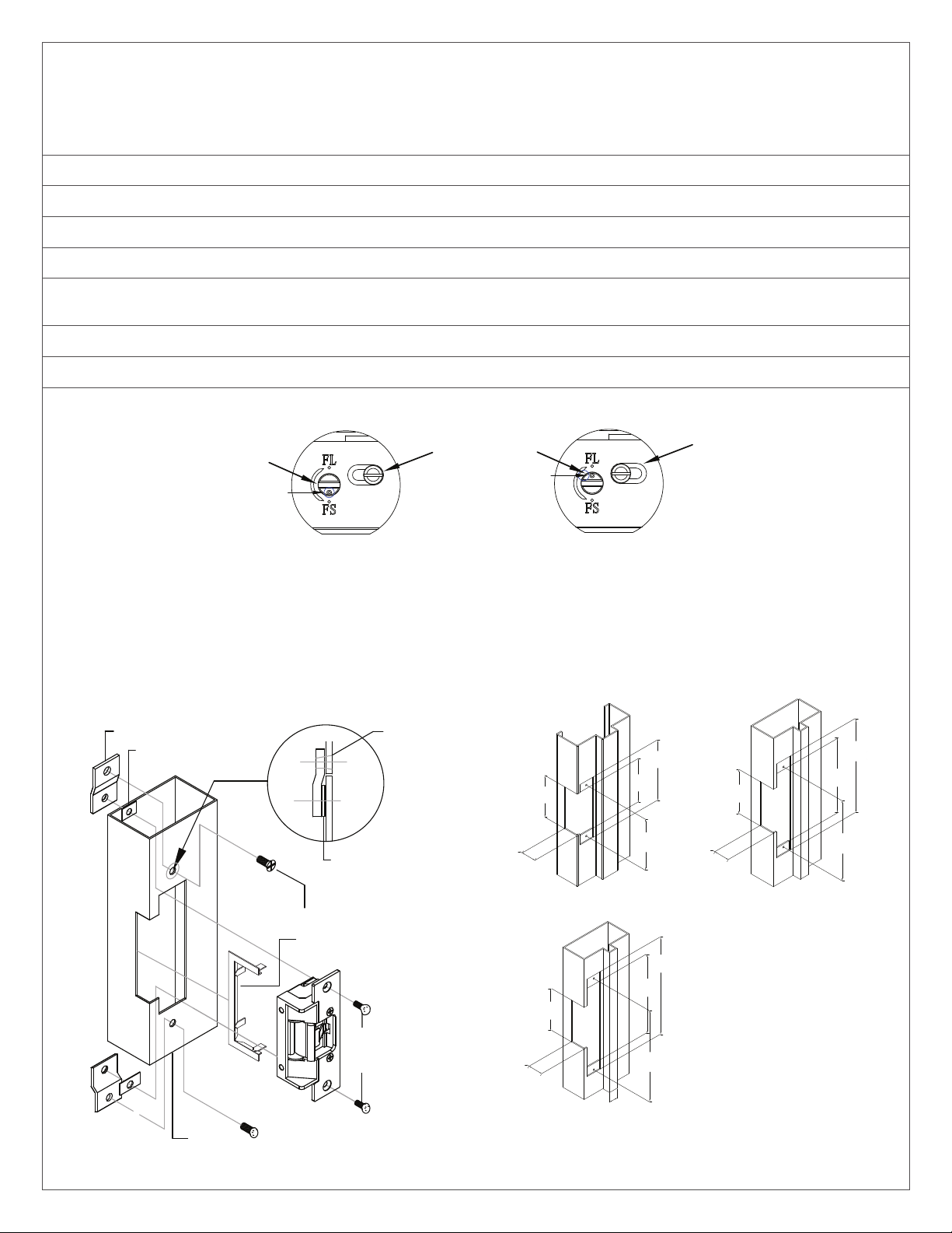
31
8''
[78.48mm]
7
8''
[22.35mm]
21
8''
[55.50mm]
13
4''
[44.70mm]
25
8''
[66.68mm]
21
4''
[55.88mm]
0''
[1.27mm]
Ă1
8''
[3.81mm]
13
8''
[34.80mm]
21
4''
[57.15mm]
17
8''
[47.63mm]
13
4''
[43.18mm]
Ă1
8''
[4.76mm]
1''
[25.40mm]
33
4''
[93.73mm]
TYP
TYP
OPEN STYLE FILAMENT & L.V. RECTIFIER USE
TRANSFORMERS
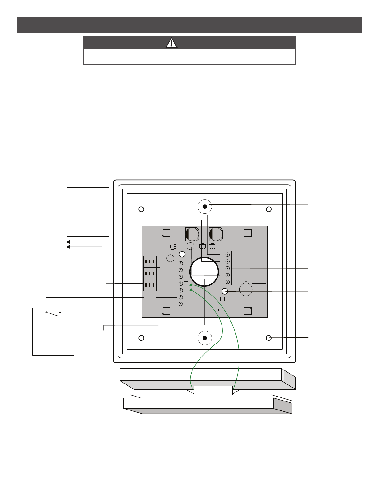
DPS switch
Wire the switch as needed for the application.
3 Set-up
LNOTE: The red dip switches (power supply dip switches) need to be set for 24V.
- Dip switch SW1 should be set to OFF
- Dip switch SW2 should be set to ON
All applications
The restroom kit has two restroom applications built in
(Mode 7 & 8). The default mode for the restroom kit is Mode
7 (normally unlocked). Determining which mode is correct
for you will be based on whether the restroom will be set to
fail safe (Mode 7) or fail secure (Mode 8). There are three
LED displays that will allow you to see what mode you have
selected when advancing through the modes. To change
the mode of the restroom kit simply press the MENU button
once and use the UP button to advance to the desired
mode.
Editing the Settings for a Mode
Typical times are pre-set for lock release and door operator
activation and is ready to use without changing any
parameters. If you need to change the timing or delay for an
output, it can be done by pressing the “MENU” button within
the mode you selected. Once the option is selected you can
use the “UP or DOWN” buttons to select the timing needed.
The first option (H & 1 flashing) will be how long relay 1 will
be activated for (0-50 seconds). The second option (d &
1 flashing) will be how long to wait before activating relay
2 (0-15 seconds). The third option (H & 2 flashing) will
be how long relay 2 will be activated for (0-50 seconds).
The fourth option (d & 2 flashing) will be how long to wait
before activating relay 3 (0-15 seconds). The fih option (H
& 3 flashing) will be how long relay 3 will be activated for
(0-50 seconds). See the chart below.
Factory Reset (Defaulting the relay module)
To return the relay module back to its factory default
settings you will need to remove power, then hold down
the “MENU” button while powering up the power supply.
Once started you will see the firmware version listed then
a number “1” will be displayed. Reconnect your power
and press the “MENU” button once then use the “UP” or
“DOWN” button to advance to the desired mode.
Fully test the operation of the restroom kit for proper
functionality.
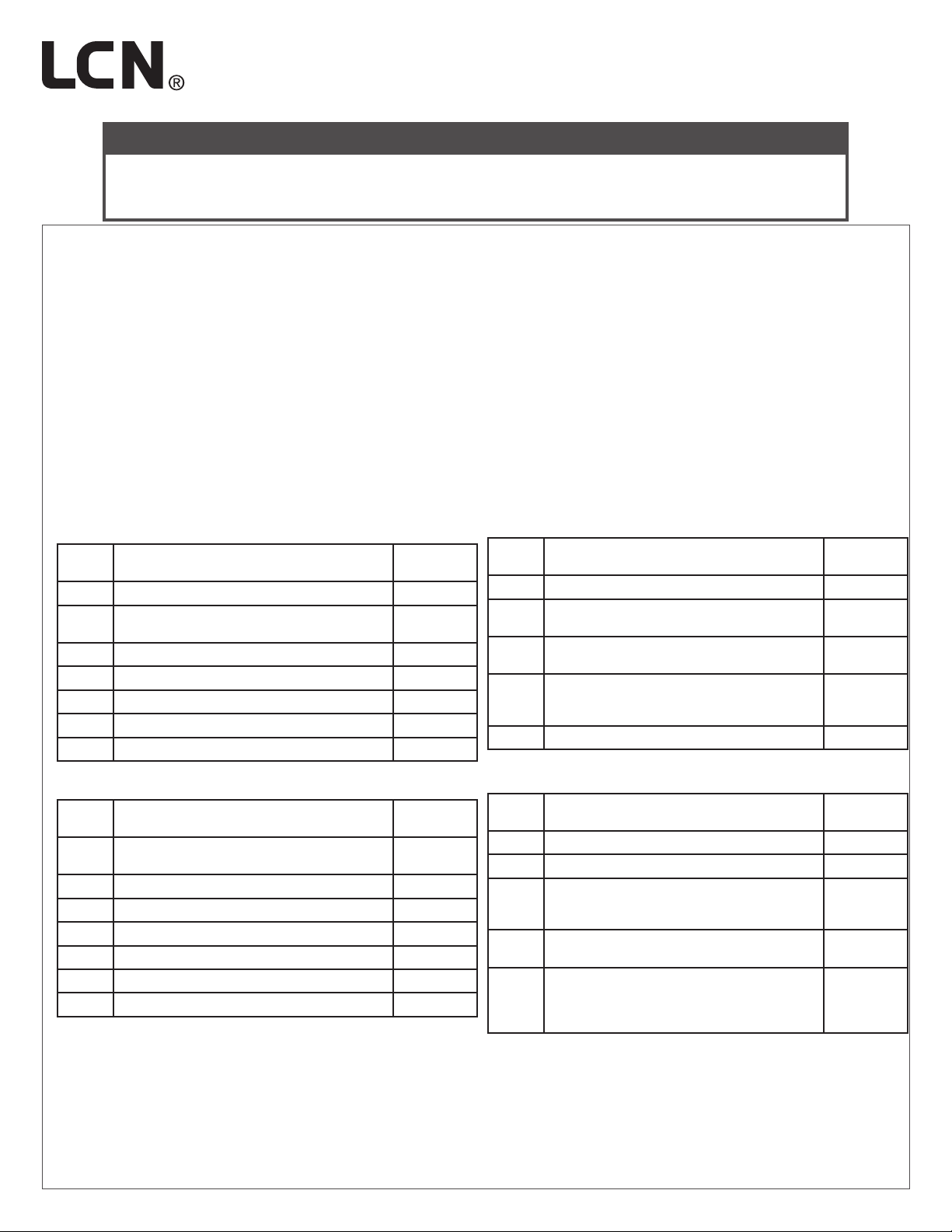
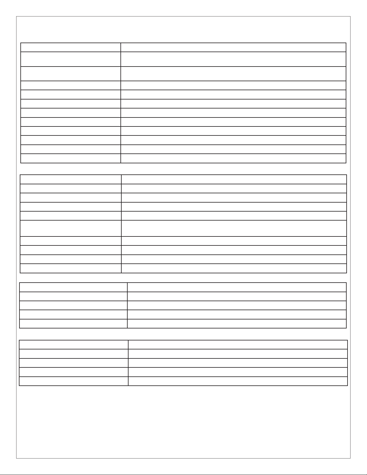
Display (M) Description (Mode you are in) Parameters (1-15)
H, then 1 Relay 1 hold time 0.0 to 50 seconds
d, then 1 Relay 2 delay time 0.0 to 15 seconds
H, then 2 Relay 2 hold time 0.0 to 50 seconds
d, then 2 Relay 3 delay time Depends on mode
H, then 3 Relay 3 hold time 0.0 to 50 seconds
d Sets the display ON or OFF during operating mode ON or OFF
AInput delay on Activate. If other than 0.0 is selected, the input must be held
in for the time period chosen before the relay module will activate. 0.0 to 10 seconds
1 Set Dry Input 1 to activate on normally open or normally closed contact. N/O or N/C
2 Set Dry Input 2 to activate on normally open or normally closed contact. N/O or N/C
3 Set Dry Input 3 to activate on normally open or normally closed contact. N/O or N/C
4 Set Dry Input 4 to activate on normally open or normally closed contact. N/O or N/C
5 Not used. Not used