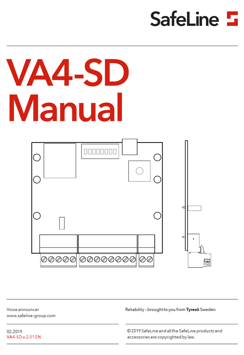
Safeline GL1 User manual

www.safeline-group.com
09.2020 © 2020 SafeLine and all the SafeLine products and
accessories are copyrighted by law.
GL1 manual
GL1 & GL1-4G v.2.1.1 EN
GSM gateways Reliability – brought to you from Tyresö Sweden

2GL1 & GL1-4G v.2.1.1 EN
Technical data
Power: Supply voltage: 10-30 VDC
Line Power: Line voltage: 48 VDC when connected to GSM network.
Current consumption: 12 VDC
250 mA, momentarily when connecting a call.
50 mA at Standby.
Communication: *GL1
- Supports 2G (900/1800 MHz)
*GL1-4G
- Supports 2G, 3G and 4G (800/900/1800/2100/2600 MHz)
Antenna connector type: SMA (female)
IP code: IP20
Dimension: 81 x 121 x 24 mm (H x W x D)
Weight: 220 gram
SIM card Micro SIM: 15 x 12 x 0,76 mm
Unit is beeing delivered with a 3 m antenna cable, SMA contact
(male).
This product is intended for use in EMEA countries.

3GL1 & GL1-4G v.2.1.1 EN
Content General information 4
Overview 5
Installation 6
Connecting the unit 6
Network services 6
Using the SIM card 7
LED Indication 8
Services 9
Increase RX audio level 9
Troubleshooting 10
Interference/poor sound quality 10
Declaration of Conformity 11

4GL1 & GL1-4G v.2.1.1 EN
This unit was built with state-of-
the-art technology and to
generally recognised safety
related technical standards
currently applicable. These
installation instructions are
to be followed by all people
working with the unit, in both
installation and maintenance.
It is extremely important that
these installation instructions
are made available at all times
to the relevant technicians,
engineers or servicing and
maintenance personnel. The
basis prerequisite for safe
handling and trouble free
operation of this system is a
sound knowledge of the basic
and special safety regulations
concerning conveyor techno-
logy, and elevators in particular.
The unit may only be used for
its intended purpose. Note in
particular that, no unauthorised
changes or additions may be
made inside the unit or indivi-
dual components.
Exclusion of liability
The manufacturer is not liable
with respect to the buyer of
this product or to third parties
for damage, loss, costs or work
incurred as a result of accidents,
misuse of the product, incorrect
installation or illegal changes,
repairs or additions. Claims
under warranty are likewise
excluded in such cases. The
technical data is the latest
available. The manufacturer
accepts no liability arising from
printing errors, mistakes or
changes.
Declaration of conformity
Download ”The declaration of
conformity” at our website:
www.safeline-group.com
Safety Precautions!
- Only trained professionals,
who are authorised to work on
the equipment, should install
and con gure this product.
- This quality product is dedi-
cated for the lift industry. It has
been designed and manufactu-
red to be used for its speci ed
purpose only. If it is to be used
for any other purpose, SafeLine
must be contacted in advance.
- It should not be modi ed
or altered in any way, and
should only be installed and
con gured strictly following the
procedures described in this
manual.
- All applicable health and
safety requirements and
equipment standards should be
considered and strictly adhered
to when installing and con -
guring this product.
- After installation and con -
guration this product and the
operation of the equipment
should be fully tested to ensure
correct operation before the
equipment is returned to
normal use.
Electrical and electronic
products may contain materials,
parts and units that can be
dangerous for the environment
and human health. Please
inform yourself about the local
rules and disposal collection
system for electrical and
electronic products. The correct
disposal of your old product
will help to prevent negative
consequences for the environ-
ment and human health.
General
information

5
765432 11
a b c
GL1 & GL1-4G v.2.1.1 EN
Overview
1. Holder
It is possible to attach the GL1 with either the DIN holder or the
optional holder.
2. Mini USB
Use the mini USB connection and the SLPro to update SW.
3. LED’s
There are three LED indicators. Refer to "LED Indication".
4. Reset button
Push the reset button for 3 sec to see GSM eld intensity.
5. Terminal
Connection for supply voltage of:
a) 10-30 VDC.
b) 0 VDC
c) Telephone line out for SafeLine phones
6. SMA-antenna connector
The SMA-antenna connector type is female.
7. SIM-card holder
The unit is using a micro SIM card.

6
0,1m²
>>1.5 m >>1.5 m
>>1.5 m
GL1
GL1 & GL1-4G v.2.1.1 EN
To avoid GSM interference: Place the GL1, the lift emergency
telephone and the GSM antenna at least 1,5 m apart.
Connecting the
unit
Installation
Network
services
Only applicable for *GL1: before you can start using a new SIM
card, the card has to be prepared and support 2G network. Cards
that only support 3G/4G will not function.
Only applicable for *GL1-4G: network services may differ from
country to country and/or service providers. Contact your service
provider for more information about 4G and VoLTE in your specic
region.

7GL1 & GL1-4G v.2.1.1 EN
Using the SIM
card
If you enter the wrong PIN
code 3 times, the SIM card will
be blocked (requires PUK code
to de-block). The GL1 cannot
be started and the LED3 will
be red.
• If the PIN code is set to ”1234”, “0000” or if it is deactivated
the SIM card can be moved from the SafeLine GL to any of the
SafeLine GSM products.
• If the PIN code is set to “1111” the SIM card cannot be moved
to any other telephone (SafeLine or otherwise) without the
PUK code.
Do not activate the voicemail or if possible ask your provider to
deactivate the voicemail.
If the PIN code is set to “1111” the SIM cards code will be randomly
changed by the SafeLine GSM unit and memorised. This way the
SIM card can only work with the SafeLine GSM unit unless you use
the PUK code for setting up a new PIN code.
If you want to upload a new SIM card with PIN code “1111” you will
need to rst upload a SIM card with PIN code “1234” or “0000” this
to clear the old code in memory.
PIN code (set to “1234”, “0000” or deactivate).
1. Insert the SIM card in an ordinary mobile phone. In the “Security
settings” menu, change the PIN code to “1234”, “0000” or set
the ”PIN code request” option to “OFF”.
NOTE! ”0000” can not be use on all SIM cards. Please contact
your service provider for details.
2. Verify the PIN code by switching your phone off and on again.
3. Make a call from your phone to verify that the SIM card is active,
before you move it to the SafeLine GL1.
4. Also make a call to SafeLine GL1 after insertion of the SIM card, to
check that it is possible to get a proper connection.
Protect the SIM card against unauthorized use.
1. Insert the SIM card in a mobile phone.
2. In the “Security settings” menu, change the PIN code to “1111”.
When the SIM card is inserted in the SafeLine unit, the code will
be changed to a random number, thus making it impossible to
use the card in another mobile phone unless it is unblocked by
means of the PUK code.

8
1 2 3
GL1 & GL1-4G v.2.1.1 EN
LED Indication
*Minimum signal strength for using GSM interface.
LED
1 2 3
GSM
Signal Strength
= 100 %
= 85 %
= 70 %
= 55 %
= 30 %*
= 15 %
= 0 %
LED1, indicates the power supply status
Continuous green Power supply OK.
LED2, indicates GSM strength
Indicates GSM strength and recieving audio level, RX-level
(please refer to the tables).
LED3, indicates communication
Continuous red GSM error.
Flashing red
(400/400 ms)
Searching for GSM network.
Flashing yellow/green
(100/100 ms)
Incoming call.
Continuous green Call connected.
Flashing green
(400/400 ms)
Call connection in progress.
Slowly ashing green
(200/4600 ms)
GSM network OK.
Flashing green
(100/100/100/2200 ms)
Handset not applied to/put on the
unit correctly.
LED

9
1 2 3
GL1 & GL1-4G v.2.1.1 EN
It is also possible to adjust the
settings via SLPro, under the
GL6 tab.
Increase the GSM receiving audio level by using of the setup mode.
1. To enter setup mode, rst disconnect the power.
2. Then pressthebuttonandhold while restartingpowerandthen for
a further 3seconds without letting go. The setup mode is now
active.
3. To setup the GSM receiving audio level press the button to reach
desired output level. The increase is in steps of 25% per push.
4. When the desired level is reached, turn off the power.
5. Then restart the unit. The new GSM receiving audio level is now
stored.
Increase RX
audio level
Services
LED
1 2 3
RX audio level
= 0 %
= 25 %
= 50 %
= 75 %
= 100 %
LED

10 GL1 & GL1-4G v.2.1.1 EN
Interference/
poor sound
quality
Bear in mind that the wiring between GL and the lift telephone/
phone is basically a standard PSTN-line and can therefore not
be placed in the lifts travelling cable together with high voltage.
***(Risk of interference)***
• Always place the antenna in an upward position and at least
1,5 m from GL.
• Place the antenna where the highest eld intensity is obtained
according to the table ("LED Indication") for the unit.
• When a call is connected try placing the antenna in different
places to nd where the best receiving/sending position is.
Trouble-
shooting
LED1 is not lit when when the unit is connected to supply
voltage.
• Check the supply voltage polarity.
• Make sure that the supply voltage is 10-30 VDC.
LED3 is lit, continous red.
• Make sure that the SIM-card is correctly positioned.
• Check that the SIM-cards PIN-code is deactivated or that the
PIN-code is set to ”1234”, ”0000” or ”1111” (see the section
SIM-card).
• Make sure that the SIM–card is activated and works by testing
the card in an mobile phone.
The call is interrupted directly after being connected.
• If the unit is powered from a battery make sure the battery is
properly charged.
• Make sure that the main power supply can deliver 300 mA
continuous current.
Call can not be connected! Error message from telephone
operator.
• To make a call, area code must always be used.

11
EU Declaration of Conformity GL1 V3.0 Your partner in lift safety
Antennvägen 10, 13548 Tyresö, Sweden
+46 (0)8-447 79 32, www.safeline-group.com
EU Declaration of Conformity
Product: Mobile network emulator
Type / model: Safeline GL1
Article no: *GL1, *GL1-4G
Manufacturer: SafeLine Sweden AB
Year: 2020
We herewith declare under our sole responsibility as manufacturer that the products referred to above
complies with the following EC Directives:
Directives
Radio Equipment (RED): 2014/53/EU
RoHS 2: 2011/65/EU
Standards applied
EN 12015:2014 EMC: Emission, Electromagnetic compatibility
EN 12016:2013 EMC/Lifts: Immunity, Electromagnetic compatibility
EN 62368–1:2014/AC:2015 LVD: Information Technology Equipment
EN 50581:2012 RoHS: Technical doc. for assessment of restriction of RoHS.
For RED 2014/53/EU, the conformity assessment procedure “Module A” used as described in Annex II. Accordingly, respective manufacturer
has done the radio modules conformity assessment:
Standards applied Article of Directive 2014/53/EU
EN 60950-1:2006+A11:2009+A1:2010+A12:2011+A2:2013 3.1 (a): Health and safety of the user
EN 62311:2008
EN 301 489-1 v2.1.1 + EN 301 489-52v1.1.0 Draft 3.1 (B): Electromagnetic Compatibility
EN 301 511 v12.5.1 3.2: Effective use of spectrum allocated
Firmware used during assessment
GL865-Dual V3: 16.00.152 / 16.01.150 / 16.01.153
SafeLine GL1: 1.00
Tyresö, 2020-03-06
Lars Gustafsson,
Technical Manager, R&D , SafeLine Group
Module
Notified body
Address
NB nr
Test nr
GL865-Dual V3
Dekra Test &Cert
Parque Tecnologico de Andalucia / SeveroOchoa 2,
29590 Spain
1909
53051 RBN.001
LE910C1-EU
Dekra Testing and
Cert
ification
Parque Tecnologico de Andalucia / Severo Ochoa 2,
29590 Málaga, Spain
1909
57536RNB.001A1
GL1 & GL1-4G v.2.1.1 EN

www.safeline-group.com
SafeLine Europe
Industrieterrein 1-8 · 3290 Diest · Belgium
Support: +32 (0)4 85 89 08 95
SafeLine Deutschland GmbH
Kurzgewannstraße 3 · D-68526 Ladenburg · Germany
SafeLine Norway
Solbråveien 49 · 1383 Asker · Norway
SafeLine Denmark
Vallensbækvej 20A, 2. th · 2605 Brøndby · Denmark
SafeLine Headquarters
Antennvägen 10 · 135 48 Tyresö · Sweden
Support: +46 (0)8 448 73 90
SafeLine Group UK
Unit 47 · Acorn Industrial Park · Crayford ·
Kent · DA1 4AL · United Kingdom
SafeLine is a registered trademark of SafeLine
Sweden AB. All other trademarks, service marks,
registered trademarks, or registered service marks
are the property of their respective owners.
Other manuals for GL1
3
This manual suits for next models
1
Table of contents
Other Safeline Computer Hardware manuals
Popular Computer Hardware manuals by other brands

PS Audio
PS Audio MultiWave II Operation manual

Conrad
Conrad 99 10 96 operating instructions

Protech Systems
Protech Systems SA-5872 Quick reference guide

Dynacord
Dynacord DRP 15 - user manual

RTI
RTI RP-1 Operations & installation guide

Sunix
Sunix Universal PCI ExpressMulti-IORS-232 / ParallelCommunication... user manual