Safety Engineering SELF BELAY User manual

OPERATIONS MANUAL
by
WARNING: INSTALLERS AND OPERATORS MUST READ THIS OPERATIONS
MANUAL AND COMPLETELY UNDERSTAND ALL REQUIREMENTS AND AGERETO
MAINTENANCE GUIDELINES.
Last revision: 2020-12-14

page 2
111v Tsarigradsko Shose blvd, 1784 Soa, Bulgaria | info@safetyeng.eu | www.safetyeng.eu
Table of contents
Table of contents .................................................................................................................................................. 2
1. Introduction and overview ........................................................................................................................... 3
2. Product identication ..................................................................................................................................... 4
3. Certication ........................................................................................................................................................ 4
4. Manufacturer information ............................................................................................................................. 5
5. Conformity assessment ................................................................................................................................... 5
6. Register your device ....................................................................................................................................... 5
7. Compatibility with autobelay devices and harness ......................................................................... 5
8. Device specication ...................................................................................................................................... 6
9. Installation ............................................................................................................................................... 7
9.1. Prepare the Self Belay device ......................................................................................................... 7
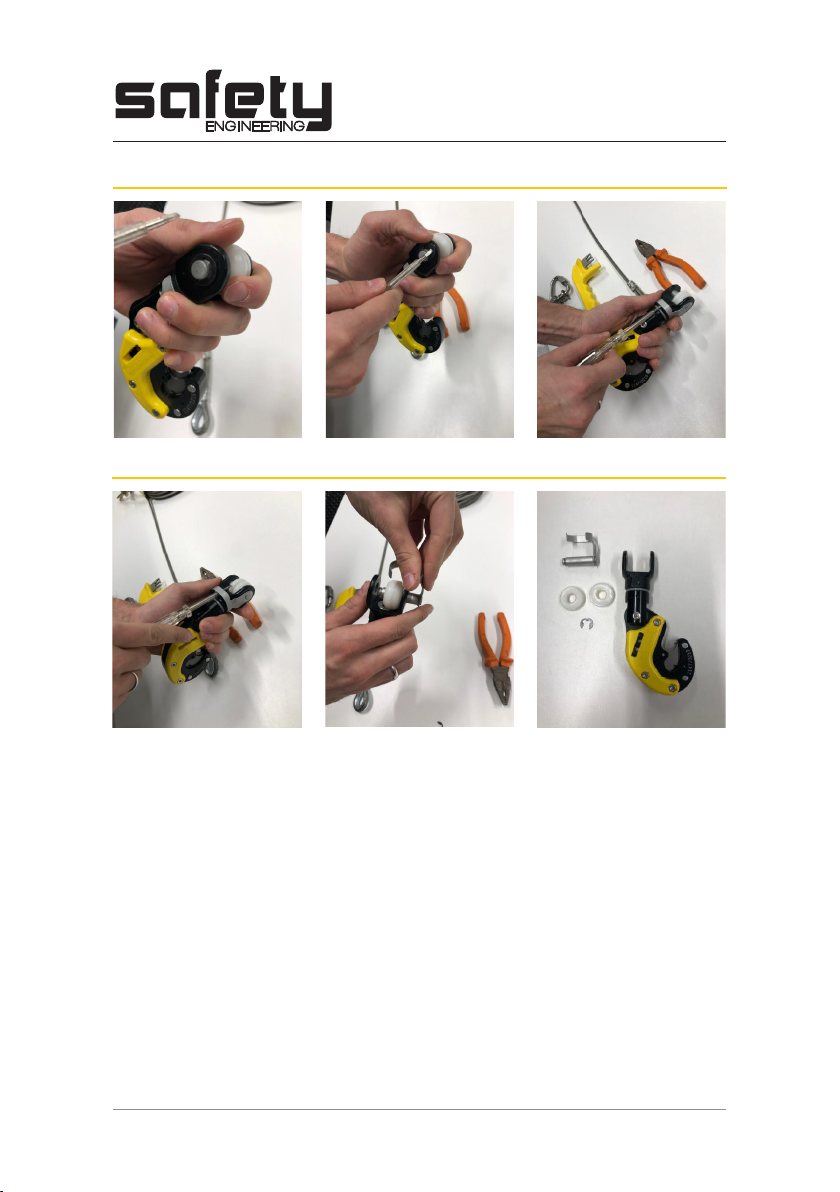
9.2. Installation on steel cable ................................................................................................................... 8
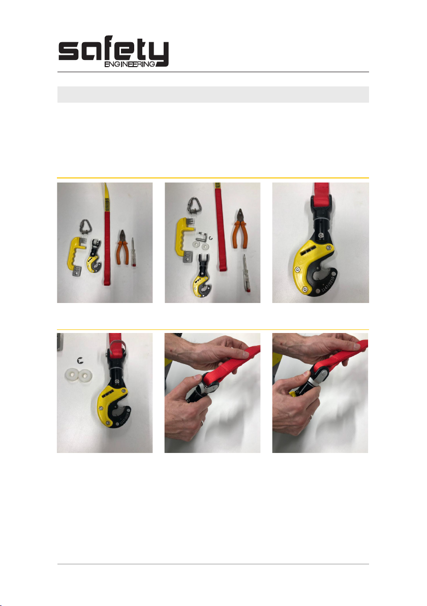
9.3. Installation on textile webbing ........................................................................................................ 9
9.4. Installation of quicklinks to user harness .................................................................................. 10
9.5. Installation of Self Belay key ........................................................................................................... 11
10. Usage of the Self Belay ........................................................................................................................... 11
11. Inspection and maintenance ................................................................................................................. 13
11.1.Dailyinspection.......................................................................................................................................13
11.2. General care ............................................................................................................................................ 16
11.3. Daily checklist ......................................................................................................................................... 18
11.4. Annual maintenance and recertication ...................................................................................... 19
12. Lifespan ....................................................................................................................................................... 22
13. Warranty information ......................................................................................................................... 22

page 3
111v Tsarigradsko Shose blvd, 1784 Soa, Bulgaria | info@safetyeng.eu | www.safetyeng.eu
1. Introduction and overview
The Self Belay is a safety connector that is used for securing oneself to the end of an auto
belay device. It adds to the safety of climbing through its unique design. The Self Belay Set is
comprised of three main parts that come packaged inside the box.
The Self Belay set includes this manual in printed form inside the box; keep this manual for
future reference. You can always download the latest version of this manual by visiting this
address:
https://safetyeng.eu/downloads/
Parts of Self Belay Set:
1. Self Belay devie - 1 pcs
2. Self Belay key - 1 pcs
3. Self Belay quicklink - 2 pcs
These components together form the Self Belay Set.
213
3

page 4
111v Tsarigradsko Shose blvd, 1784 Soa, Bulgaria | info@safetyeng.eu | www.safetyeng.eu
XXXX/MMYY XXXX – Serial No. in batch
MM – Month of manufacture (e.g. 03 - March)
YY – Year of manufacture (e.g. 17 - 2017)
EN 362:2004/T Device complies with EN 362:2004 as a class T connector
20 kN Major axis breaking load
Read the instructions for use
Complies with Regulation 2016/425 of European Union
0123 Number of notied body performing conformity aseessment
EP3115084B1 Self Belay patent number
Self Belay devices are marked with some identifying information; the image below shows the
location of important product labelling.
This device is certied as a class T connector per EN 362:2004 - Personal protective equipment
against falls from a height - Connectors.
2. Product identication
XXXX/MM/YY
0123
A3
DO NOT INTERPRETATE THE DRAWING : IF YOU HAVE QUESTIONS, CONTACT US
The property and use of this design are protected by the law for the exclusive use of Safety Engineering Ltd.
Weight / Маса
Material / Материал
Treatment / Обработка
Листов формат
Собствеността на този дизайн е защитена от Закона за авторски права на Сейфти Инженеринг ООД
НЕ ИНТЕРПРЕТИРАЙТЕ ЧЕРТЕЖА : АКО ИМАТЕ ВЪПРОСИ, СВЪРЖЕТЕ СЕ С НАС
N
drawing / N
чертеж
Description / Описание
Scale / Мащаб
Drawn / Начертал
Checked / Проверил
Approved / Одобрил
Date / ДатаDate / ДатаDate / Дата
Sheet format
Revision
Tolerance / Допуск
ISO 2768 M
Chamfers / Фаски
0.5 x 45
Modification / Промени
Drawn / Начертал
Date / Дата
N
Ревизия
ERP number / ЕРП номер
Signature / Подпис
Signature / Подпис Signature / Подпис
0.17 kg
2:1
Self Belay main body
SE.SB.A00001
13
3.2
Signature / Подпис Signature / Подпис
2020-12-10 - C:\PDM-2019\Products\SB Self Belay\SE.SB.M00001
All sharp corners chamfered 05x45°
1.
Unspecified radii - R1
2.
СЛЕД ЗАВАРКА ДЕТАЙЛА СЕ ПОДЛАГА
НА ГОРЕЩО ПОЦИНКОВАНЕ
3. Certication

page 5
111v Tsarigradsko Shose blvd, 1784 Soa, Bulgaria | info@safetyeng.eu | www.safetyeng.eu
4. Manufacturer’s Details
5. Conformity assessment
6. Register your device
7. Compatibility with autobelay devices and harness
Safety Engineering Ltd.
Address: Tsarigradsko shose 111V, 1784 Soa, Bulgaria
VAT No: BG175376730
Conformity assessment according to Annex VII of Regulation 2016:425 performed by:
TÜV SÜD Product Service GmbH Zertizierstellen
Ridlerstraße 65
80339 Munich
Germany
Notied Body number: 0123
Visit https://safetyeng.us/register-my-device/ to activate your device warranty and receive
important product updates.
The Self Belay set is compatible with the following auto belay devices:
• Onbelay 8, 11, 14 and 17 manufactured by Safety Engineering Ltd.
• Trublue and Trublue XL manufactured by Head Rush technologies
• Perfect Descent Direct Drive and Perfect Descent Speed Drive manufactured by C3
Manufacturing LLC (Perfect Descent)*(see notice below)
The Self Belay set is compatible with harnesses that conform to the following standards:
• EN 361 - Personal protective equipment for prevention of falls from a height – Full body
harness.
• EN 813 - Personal protective equipment for prevention of falls from a height – Sit
harness.
• EN 12277 - Mountaineering equipment - Harnesses - Safety requirements and test
methods. Types A (full body harness), B (small full body harness) and C (sit harness) are
approved for use.
NOTICE: The Self Belay body can be retrotted to C3 Manufacturing LLC (Perfect Descent)
devices, but Safety Engineering has no formal contract with the manufacturer. Therefore, the
client must contact C3 Manufacturing LLC (Perfect Descent) before installing the Self Belay
device on their belays!

page 6
111v Tsarigradsko Shose blvd, 1784 Soa, Bulgaria | info@safetyeng.eu | www.safetyeng.eu
8. Device specications
Dimensions as installed:
Width: 63 mm Height: 200 mm (including quick link Delta assembly)
Depth: 27 mm Weight as installed: 320 g
Main body
Material: EN AW 2017A, AISI 304
Min. breaking strength: 20 kN axial load
Device gate opening: 11 mm
Quicklink delta assembly
Material: AISI 304
Min. breaking strength: 30 kN axial load
Device gate opening: 11 mm
61.80
155.17
26
36.80
27.90
26.50
25
Self belay with webbing
SB.01.00.00.00W
Petrov
Tapankov
WEIGHT: 295.91 g
A3
SHEET 1 OF 3
SCALE:1:1
DWG NO.
TITLE:
REVISION
DO NOT SCALE DRAWING
MATERIAL:
DATE
SIGNATURE
NAME
DEBUR AND
BREAK SHARP
EDGES
FINISH:
UNLESS OTHERWISE SPECIFIED:
DIMENSIONS ARE IN MILLIMETERS
SURFACE FINISH:
TOLERANCES:
LINEAR:
ANGULAR:
Q.A
MFG
APPV'D
CHK'D
DRAWN

page 7
111v Tsarigradsko Shose blvd, 1784 Soa, Bulgaria | info@safetyeng.eu | www.safetyeng.eu
22
56
80
13.50
8
Self belay with webbing
SB.01.00.00.00W
Petrov
Tapankov
WEIGHT: 295.91 g
A3
SHEET 3 OF 3
SCALE:1:1
DWG NO.
TITLE:
REVISION
DO NOT SCALE DRAWING
MATERIAL:
DATE
SIGNATURE
NAME
DEBUR AND
BREAK SHARP
EDGES
FINISH:
UNLESS OTHERWISE SPECIFIED:
DIMENSIONS ARE IN MILLIMETERS
SURFACE FINISH:
TOLERANCES:
LINEAR:
ANGULAR:
Q.A
MFG
APPV'D
CHK'D
DRAWN
71
181
23
53
26.23
32
45
66
4
16
29.56
Self belay with webbing
SB.01.00.00.00W
Petrov
Tapankov
WEIGHT: 295.91 g
A3
SHEET 2 OF 3
SCALE:1:1
DWG NO.
TITLE:
REVISION
DO NOT SCALE DRAWING
MATERIAL:
DATE
SIGNATURE
NAME
DEBUR AND
BREAK SHARP
EDGES
FINISH:
UNLESS OTHERWISE SPECIFIED:
DIMENSIONS ARE IN MILLIMETERS
SURFACE FINISH:
TOLERANCES:
LINEAR:
ANGULAR:
Q.A
MFG
APPV'D
CHK'D
DRAWN
9. Installation
9.1. Prepare the Self Belay device
In order to successfully install self belays on auto belay devices, you will need the following
tools:
• A at screwdriver
• Set of pliers
For installation on steel cable, see sections Prepare the Self Belay device and Installation on
steel cable.
For installation on textile webbing, see sections Prepare the Self Belay device and Installation
on textile webbing.
The installation of the Self Belay on a steel cable includes the following steps:

page 8
111v Tsarigradsko Shose blvd, 1784 Soa, Bulgaria | info@safetyeng.eu | www.safetyeng.eu
Lift and remove the pin assembly and the plastic washers:
Remove the lock washer with a at screwdriver from the folding bolt:

page 9
111v Tsarigradsko Shose blvd, 1784 Soa, Bulgaria | info@safetyeng.eu | www.safetyeng.eu
9.2. Installation on steel cable
With the Self Belay device prepared, position the cable between the plastic washers:
Insert the folding bolt and lock it to the body of the swivel. Make sure the bolt is securely
fastened and cannot be detached from the device by hand.
Reinstall the lock washer with pliers. Make sure the washer snaps all the way in the groove.
After assembly, verify that the washer cannot be removed by hand.
Reinstall the lock washer with pliers. Make sure the washer snaps all the way in the groove.
After assembly, verify that the washer cannot be removed by hand.

page 10
111v Tsarigradsko Shose blvd, 1784 Soa, Bulgaria | info@safetyeng.eu | www.safetyeng.eu
9.3. Installation on textile webbing
Self Belay can be installed on textile webbing of width 20 mm. Installation on other webbing
sizes is not recommended.
Before you proceed, remove the plastic washers and keep them together with the original
device packaging.
Place the loop of the webbing inside the opening on top of the device:
Insert the folding pin through the device and the webbing loop, then press it towards the
device until it snaps rmly in place:

page 11
111v Tsarigradsko Shose blvd, 1784 Soa, Bulgaria | info@safetyeng.eu | www.safetyeng.eu
Reinstall the lock washer with pliers. Make sure the washer snaps all the way in the groove.
After assembly, verify that the washer cannot be removed by hand.
9.4. Installation on quicklinks to user harness
The quicklink must be fastened securely to the harness of the user to ensure their continuous
safety when using the device. Refer to section Compatibility with autobelay devices and
harness for a list of compatible harnesses.
To attach:
1. Loosen the quick link nut by means of a wrench and open it completely
2. Identify the anchor point loop intended for attachment to fall arrest system. Refer to the
harness user manual for the location of this attachment point.
3. Tighten the quicklink by using a wrench. Tightening torque: 3 Nm (2.21 lb.ft).
4. After installation, make sure the nut cannot be turned by hand.
WARNING: Use only harnesses compatible with the Self Belay. Usage of other types
of harnesses is not supported and does not guarantee end user safety!

page 12
111v Tsarigradsko Shose blvd, 1784 Soa, Bulgaria | info@safetyeng.eu | www.safetyeng.eu
9.5. Installation of Self Belay key
10. Usage of the Self Belay
The Self Belay key is intended to be attached securely at a safe location where the user
connects and disconnects themselves from the device.The key features rectangular openings
for attachment by means of webbing, and a circular hole for a connector or other attachment
To attach:
• Insert the quicklink in the opening of the Self Belay device. Push the quicklink all the way
down into the device; the locking discs of the device rotate as you push the quicklink.
• When the quicklink is properly inserted, the Self Belay key can now be removed; pull it
away and release it.
• Make sure that the device is properly locked; try removing the quicklink from the device
to verify that it is rmly secured in place.
• Start climbing!
For maximum comfort during use by adults, the recommended height of installation of the
key is around 800-900 mm (32-35 in.) from the oor. Adjust accordingly to accommodate
children.
It is strongly recommended to install protective ooring at locations where the
Self Belay is used, or provide means to prevent the key from being dropped on
the ground between uses. While the key by itself is sturdy enough to sustain such
damage, repeated drops from height may cause its unlocking features to bend or
break, causing downtime and unsafe operation.
Note that Self Belay keys showing signs of being dropped repeatedly during normal
usage of the device are not subject to warranty replacement.
Self Belay device is intended for use by a single person of weight no more than 130
kg, including their other personal protective equipment. It is strictly prohibited using
the device to secure more than one person, or to use it to lift and transport goods.
USAGE WARNING: Only use the Self Belay as instructed in this manual and only for
its intended purpose. If malfunction is suspected, stop operating the device and
inspect the unit. The supplier and manufacturer are not liable for damage due to
improper use or device alteration.
Before use, always make sure the Self Belay device, key and quicklink have been
properly installed. Refer to section Installation for detailed instructions.
To avoid the possibility of accidents and misuse, ALWAYS make sure that the Self
Belay key is attached securely to an unmovable structure or object. Failure to secure
this requirements may lead to personal injury and death.

page 13
111v Tsarigradsko Shose blvd, 1784 Soa, Bulgaria | info@safetyeng.eu | www.safetyeng.eu
To detach:
• Take the Self Belay key and insert it all the way in the opening on the side of the Self
Belay.
• Pull the quicklink away from the device.
• You are now disconnected from the Self Belay

page 14
111v Tsarigradsko Shose blvd, 1784 Soa, Bulgaria | info@safetyeng.eu | www.safetyeng.eu
11. Inspection and maintenance
11.1. Daily inspection
Careful inspection is paramount to maintaining device safety; perform the inspection
procedures outlined in this section diligently and in a timely manner. Failure to follow
these procedures may lead to severe personal injury or even death!
You as an end user or operator assume complete responsibility for incidents arising
from lack of timely inspection and/or maintenance.
Self Belay device and its components shall be inspected daily before the start of each work
day in order to ensure their safety and smooth operation. The following procedures shall be
followed in order to ensure optimal safety and eciency.
1.Overall device check
Inspect visually the Self Belay device; note any missing, deformed or broken components.
Note: during use, it is normal for the device to receive occasional scratches and accumulate
surface damage from contact with rough surfaces. Coating will also start wearing out,
particularly in areas where the device is being held while opening or closing, as well as areas
around the key and quicklink opening This is normal and to be expected.
2. Self Belay key check
Inspect closely the Self Belay key; pay particular attention to the condition of the middle pin.
If it is bent, partly or completely broken, stop using the key and replace it immediately.

page 15
111v Tsarigradsko Shose blvd, 1784 Soa, Bulgaria | info@safetyeng.eu | www.safetyeng.eu
3.Self Belay key measurement
Measure the width of the middle pin of the Self Belay key as shown; measured value should be
above 2.8 mm. This dimension is between 3.6 and 3.8 mm as manufactured; if the measured
value is close (but still above) 2.8 mm, consider ordering replacement keys.
If the key fails the measurement check, replace it immediately before using the device again.
4.Self Belay covers check
The plastic covers on both sides should be inspected for cracks and damage; missing or
damaged covers should be replaced in a timely manner. Note that the covers are not part of
the warranty for the device as they are considered consumable.

page 16
111v Tsarigradsko Shose blvd, 1784 Soa, Bulgaria | info@safetyeng.eu | www.safetyeng.eu
5.Swivel check
The condition of the swivel must be checked by twisting the upper part as shown in Photo 1
below. It should rotate freely in both directions.
5. Swivel pin check
Inspect the swivel pin for damage or deformation; stop using the device immediately if the
pin is broken or deformed!
If the swivel is deformed, damaged or shows signs of cracking, stop using the device
immediately. Contact Safety Engineering for a replacement.
Make sure that the lock washer in the end of the swivel pin is present and cannot be removed
by hand. If the washer has fallen out, stop using the device until the washer is replaced.
Check highlighted area for
cracks, deformations or damage
Devices with damaged or
deformed swivels must not be
used

page 17
111v Tsarigradsko Shose blvd, 1784 Soa, Bulgaria | info@safetyeng.eu | www.safetyeng.eu
7. Quicklink check
Inspect the quicklinks that are currently in use on participant harnesses; note any damage,
cracks or permanent deformation of the quicklink. Make sure the attachment rotates freely.
Check for wear the place where the quicklink is in contact with the harness; if there is visible
wear, measure the smallest thickness in the worn out place; minimum thickness should be at
least 6.5 mm.
Make sure the nut of the quicklink is tightened well when installed on the harness. If loose,
tighten carefully (maximum torque: 3 N.m)
If the quicklink is deformed, damaged or worn out beyond threshold value given above, stop
using the quicklink and replace it immediately.
8.Functional check
When all previous checks are completed, proceed to check the functionality of the device.
Insert quicklink in the device as normal; the quicklink should slide in easily and without eort.
Rotation of the discs should be smooth and without friction.
If the discs rotate with diculty, apply dry lubricant in spray form (e.g. graphite or silicone-
based) and insert the quicklink several times to spread out the lubricant.
With the quicklink inserted all the way, remove the key from the device; key should slide out
easily without excessive eort.
When the key is out of the device, verify that the Self Belay is rmly locked and the quicklink
cannot be taken out.
Replace the key in the device and remove the quicklink from the Self Belay; quicklink removal
should be easy and not require excessive eort.
Verify that the key cannot be removed from the device when the quicklink is not inserted.
Repeat the steps above at least 3 times.

page 18
111v Tsarigradsko Shose blvd, 1784 Soa, Bulgaria | info@safetyeng.eu | www.safetyeng.eu
The following instructions are provided as general recommendation in order to prolong the
life of the device; they are not obligatory.
• Cleaning (device only): Clean the exterior of the Self Belay device with a damp cloth
with small amount of mild detergent. Do not submerge the device in water! Let the
device dry completely before next use.
• Cleaning, (Self Belay key and quicklink): These components are made from stainless
steel and are safe to wash. Use mild detergent and wash well. Let the components dry
naturally before use.
• Disinfection. Use pure ethanol only (at least 80% proof). Spray or pour small amount
on a dry cloth and clean thoroughly. If using spray, make sure not to spray directly
inside the device; always apply the disinfectant to a cloth and clean thoroughly. Let the
components dry before subsequent use.
• Lubrication: Small amount of general-purpose, low viscosity silicone oil or graphite-
based dry lubricant in spray form can be used.
• Storage: Keep in dry, well-ventillated place away from direct sunlight, extreme
temperatures, and corrosive or aggressive substances.
11.2. General care

page 19
111v Tsarigradsko Shose blvd, 1784 Soa, Bulgaria | info@safetyeng.eu | www.safetyeng.eu
11.3. Daily checklist
Component Check Action Frequency
Self belay
device
Is it damaged,
deformed, or have
missing parts?
Stop using the device immediately.
Contact manufacturer for replacement
device.
Daily
Missing, damaged or
deformed covers?
Replace covers; device may still be
continue to be used. Daily
Quicklink dicult to
insert in the device or
jams?
Apply lubrication and operated the
device several times.
If problem persists, contact manufac-
turer for replacement device.
Daily
Self Belay key
Missing or deformed
middle pin? Stop using the key immediately. Daily
Middle pin thickness
below 2.8 mm? Stop using the key immediately. Daily
Self Belay
quicklink
Badly damaged or
deformed? Stop using the quicklink immediately. Daily
Minimum thickness
below 6.5 mm? Stop using the quicklink immediately. Daily
Self Belay
swivel
Damaged or de-
formed?
Stop using the device immediately.
Contact manufacturer for replacement
device.
Daily
Folding pin deformed
or damaged?
Stop using the device immediately.
Replace the folding pin. Daily
Missing or deformed
lock washer
Stop using the device.
Replace the washer. Daily

page 20
111v Tsarigradsko Shose blvd, 1784 Soa, Bulgaria | info@safetyeng.eu | www.safetyeng.eu
11.4. Annual maintenance and recertication
WARNING: Failure to send devices for inspection within the time frame outlined
below could result in serious injury or death.
1. 11 months after the Self Belay/s have been in use, the customer contacts the
2. For a xed price, the manufacturer sends out new or refurbished devices to the client.
The client is then required to send back their old devices to the manufacturer within
a week of receiving the replacement ones. This is to ensure that the old devices
are not mistakenly still used after the reception of the replacement devices. Visit
https://safetyeng.us/product/self-belay-re-certication (USA and Canada)
https://safetyeng.eu/product/self-belay-re-certication/ (Europe and rest of the
world) for more information and pricing.
3. The new or refurbished devices are warranted for a further 12 months from the date of
arrival to the client.
4. Any damages that make the Self Belay unsafe within the warranty period will be dealt
with as dened in section Warranty information Warranty information.
Components of the Self Belay that may need to be replaced during annual maintenance
Body cover
Side cover,left
Main body
Parallel pin
ISO 8734 - 4x10 - A - St
Hex socket head cap screw
ISO 4762 M4x25 - A2
Swivel sleeve
Swivel pin
Leaf spring
Hex nut ISO 4032 M4 - A2
Parallel pin
ISO 8734 - 3x10 - A - St
Locking anchor
Swivel assembly
Side cover, right
Locking disc, side
Locking disc, central
Torsion spring
Flat round head rivet
DIN 674 - 3x16 - St
Body cover
Side cover,left
Main body
Parallel pin
ISO 8734 - 4x10 - A - St
Hex socket head cap screw
ISO 4762 M4x25 - A2
DIN 674 3x16 - St
Swivel sleeve
Swivel pin
Leaf spring
Hex nut ISO 4032 M4 - A2
Parallel pin
ISO 8734 - 3x10 - A - St
Locking anchor
Swivel assembly
Side cover, right
Self belay with webbing
1:1309.68 g
Signature / ПодписSignature / ПодписSignature / Подпис
ERP number / ЕРП номер
Ревизия
N
Date / Дата
Drawn / Начертал
Modification / Промени
0.5 x 45
Chamfers / Фаски
ISO 2768 M
Tolerance / Допуск
Revision
Sheet format
Date / Дата Date / Дата Date / Дата
Approved / Одобрил
Checked / Проверил
Drawn / Начертал
Scale / Мащаб
Description / Описание
N
drawing / N
чертеж
НЕ ИНТЕРПРЕТИРАЙТЕ ЧЕРТЕЖА : АКО ИМАТЕ ВЪПРОСИ, СВЪРЖЕТЕ СЕ С НАС
Собствеността и изпозването на този дизайн са защитени от закона за авторски права на УОЛТОПИЯ АД
Листов формат
Treatment / Обработка
Material / Материал
Weight / Маса
The property and use of this design are protected by the law for the exclusive use of WALLTOPIA AD
DO NOT INTERPRETATE THE DRAWING : IF YOU HAVE QUESTIONS, CONTACT US
A2
3.2
2/18/2020 - Exploded mockup
All sharp corners chamfered 05x45°
1.
Unspecified radii - R1
2.
Other manuals for SELF BELAY
2
Table of contents
Other Safety Engineering Safety Equipment manuals
Popular Safety Equipment manuals by other brands

Bettersafe
Bettersafe Fall Angel Sky Angel installation manual

SafeWaze
SafeWaze FS-EX311 instruction manual

IKAR
IKAR ABS 5 B Log book and instructions for use

KRATOS SAFETY
KRATOS SAFETY FA 20 400 03 manual

Schletter
Schletter PROLINE ROOF HOOK installation guide

Omron
Omron Sti F3SJ-B P25-02TS Series instruction sheet