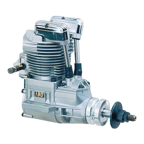
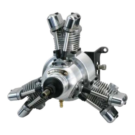
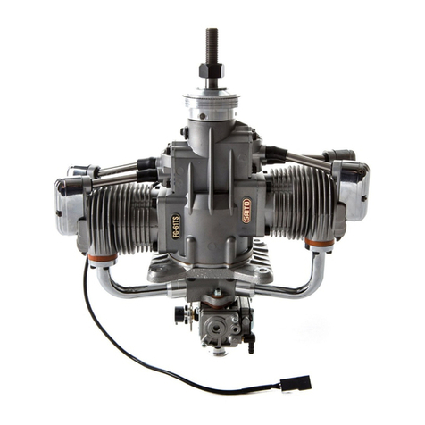
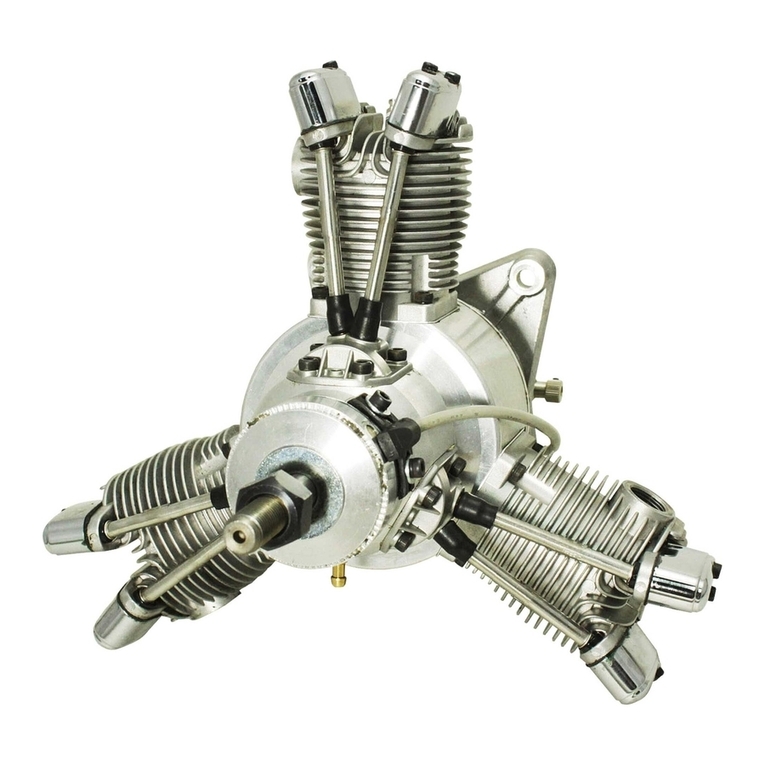
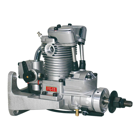
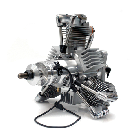
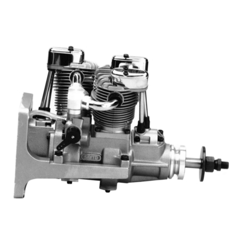
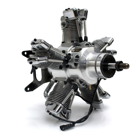
Φ29.0mm 22.0mm 72.7cc
22”x10”〜23”x10”
Bore
Mainbody:2,600g/Muffler:280g/Ignition:380g
Stroke Disp.
Weight(Approx.) RPMRange Approx.1,200-7,800rpmMaxonground Approx.6,200~7,500rpm
Propeller 1/4-32SP-1or
SP-2sparkplug
Plug
Optionalparts
2st-Gasoline50㏄classApplications
Batteryforignitionsystem Voltage:6-8.4V,greaterthan1,500mA
・Limitgauge(0.1t)fortappetadjustment 1pc ・Wrenchfortappetadjustinglocknut 1pc ・Plugwrench 1pc
・Sparkplug[SP-2](Attachedtotheengine) 5pcs ・Mufflerset 1set ・Anti-looseningnut 1pc
・Ignitionsystem(w/sensor) 1set ・Mufflerlocktie 2pcs ・Hexagonalwrench1.5mm 1pc
Specifications
FG-73R5InstructionManual
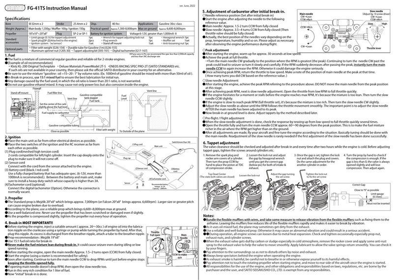
2.Ignition
●Placethemainunitasfarfromotherelectricaldevicesaspossible.
●PlacethetwoswitchesoftheignitionandtheRCreceiverasfarfrom
eachotheraspossible.
(1)Plugcord(meshedhightensioncord)
Inserttheplugcapof(1)Plugcorddeeplyontotheplugof#1cylinder
tomakesureitwillnotcomeoff.Theothercapsandplugsshouldbe
installedbythesameway.(Refertocylinder#onthereverseside)
(2)Sensorcord
Connectwiththecordfromthesensorattachedtotheengine.
(3)Batterycord(black/redcord)
Useafullychargedbatterythathasadequatespec.(6-8.4V,morethan
1500mAisrecommended).Betweenthebatteryandmainunit,make
suretoinstallaheavydutyswitchwhosecapacityishigherthan3A.
(4)Tachometercord(optional)
Connectthedigitaltachometer(Option)tothemainunit.Otherwisetheconnectorisnormallyvacant.
Standard
accessories
FuelTank FuelLevel
ToOutsideoftheplane
Ventline
Fuelsupplytocarburetor
Fuelfillerline
Ventline
Gasoline-compatible
tankstopper
Gasoline-compatibletubing
Filterwithweight
Setthecenterofthecarb
slightlyabovethefuellevel
Closeaspossible
Hollow
out
Firewall
Approx.30mm
1.Fuel
●Thefuelisamixtureofregulargasolineandhigh-quality2-strokeengineoil.
●[Exampleofoilrecommendation]
・KlotzKL-200OriginalTechniplate・DeluxeMaterialsPowerModel2T-Setc.
●Besuretousethemixture“gasoline:oil=15~20:1”byvolumeratio.(Ex.1000mlofgasolineshouldbemixedwithmorethan50mlofoil).
●Duringthebreak-inprocess,use15:1mixedfueltoensurethebestlubricationforinitialrunning.
●Anydamagecausedbythefuelused,inwhichtheoilratioislowerthan20:1willnotbecoveredbywarranty.
●Donotusegasolinecontainingethanol.Itmaycausenotonlypowerlossbutalsocorrosioninsidetheengine.
・Filterwithweight[G36-154] ・Rubbertubeforgasoline(1m)[G36-155]
・Tappetadjustingkit[30-161] ・Digitaltachometer[G17-167]
3.Propeller
●RecommendedpropellerisMejzlikD22”xP10”whichbringsapprox.7,100rpm.
●Useareliablepropwhichbringsmaximum6,500~7,500rpminconformitytoyourplane.
●Useawell-balancedprop.Neveruseapropthathasbeenscratchedordamagedevenifslightly.
●Neveruseexcessivelylightorheavyloadedprop.Theymaycauseenginefailure,bigaccident,oreveninjury.
●Asthepropelleriscompressedslightly,tightenthepropellernuteveryhourofoperation.
4.Break-inMOSTIMPORTANT!!
●Beforestartingtheengine,injectasuitableamount(approx.20〜30cc)ofengineoilintothelubricationnippleonthecrankcaseusinga
syringeorpumpwhileturningthepropellerbyhand.Afterthat,plugthisnipple.Asexcessisdischargedfromthebreathernipple,attacha
tubetothebreathernipple.
●Prop-recommendationforbreak-inprocess:Mejzlik22”x10”
●Use15:1fuel:oilratioforbreak-in.
●Nevermakethefuelmixtureleanduringbreak-in.Itcouldcauseseizureevenduringidlingor
low-speedrunning.
●Beforestartingtheengine,openthemainneedleapprox.2turnsfromfullyclosed.
●Starttheengine(usingastarterisrecommendedforsafety).
●Runfor15~20secondsatlowspeedtowarmup.
●Openthrottlegraduallyuptofull.InthemeantimeturnthemainneedleCCW.Continuetoturnthe
mainneedleCCWtodropto3,000~4,000rpmkeepingthethrottleopenedfully.
●Runinthisveryrichconditionfor1literormoreoffuel.
●Now“initial”break-inisdone.
ver.Sept,2019
SwitchCapacity:3A〜
Sensor
Battery
Voltage:6-8.4V
Capacity:1,500mA〜
PlugCap
(2)Sensorcord
(
1)PlugCord
MainUnit
(3)BatteryCord
(4)TachometerCord
Throttle
Fullopen
CCWtomake
rich
Main
Needle
CW→Lean
CCW→Rich
CW→Lean
CCW→Rich
CCW→Rich
CW→Lean
Mainneedle Slow(Idle)Needle
(Adjustwith⊖screwdriver)
Slow
High
Throttlelever
5.Adjustmentofcarburetorafterinitialbreak-in.
◇Needlereferenceposition(Setafterinitialbreak-in)
●Starttheengineafteradjustingtheneedletothefollowingreferencevalue.
●Mainneedle:Approx.1+1/2turnsCCWfromfullyclosed
●Slowneedle:Approx.7turnsCCWfromfullyclosed(Thenthrottlevalve
shouldbefullyclosed)
●Actually,thebestpositionoftheneedlesvarydependingontheprop,
temperature,humidityandsoon.Pleaseadjustasnecessaryafterobserving
theengineperformanceduringflight.
◇Peakadjustment
●Afterstartingtheengine,warmupforapprox.30secondsatlowspeed.
●Achievethepeakatfullthrottle.
→TurnthemainneedleCWgraduallytothepositionwheretheRPMisgreatest(thepeak).ContinuingtoturntheneedleCWpastthepeak
couldleadtoseizuresoturnitslowlyandcarefully.IftheRPMsuddenlydecreasesafterpassingthepeak,instantlyturnthemainneedle
CCWtoagainincreasetheRPM.Otherwiseitcoulddamagetheengineseriously.
●OnceachievingpeakRPM,returnthethrottletolowspeed.Makeanoteofthepositionofmainneedleatthepeakatthattime.(Howmany
turnsyoudidCWbasedonthereferencevalue.)
◇SlowneedleAdjustment
●AfterachievingpeakRPM,nextisslowneedleadjustment.OpenthethrottlefromlowRPMtofullthrottlequickly.
●IftheenginehesitatesforamomentorstallsbeforetheenginereachesmaxRPM,Itʼsbecausethemixtureistoolean.Thenturntheslow
needleCCWslightly.
●IftheengineisslowtoreachpeakRPM(fullthrottleset),itʼsbecausethemixtureistoorich.ThenturntheslowneedleCWslightly.
●AdjusttheslowneedleasaboveuntiltheRPMfollowsthethrottlemovementsmoothly.Theimportantpointistoadjusttheslowneedle
AFTERthemainneedlehasbeenadjustedtoitspeak.
●Nowbreak-inatgroundlevelisdone.Adjusttappetsbythemethoddescribedlater.
◇Pre-flight/Flightadjustment
●Whentheslowneedleadjustmentisdone,checktheresponsebyrevvingupfromlowspeedtofullthrottlequicklyseveraltimes.
●OpenthethrottlefullyandturnthemainneedleCCW4~6clicksfromthepeakposition.Thisistomakethefuelmixturericherintheair
wheretheRPMgethigherthanontheground.
●Afteralladjustmentsaremade,flyyouraircraftandfinetunetheengineaccordingtothesituation.Basicallytuningshouldbedonewiththe
mainneedle.Readjustmentoftheslowneedleisrarelyneededifthefirstadjustmentoftheslowneedlehasbeendonesuccessfully.
CorrectGap
Mustnotbeinserted
Closeto“0”withnolimit
Limitgauge
(0.1mm)
Loosenthelocknut
Adjustthegapturning
thesetscrew
TopDeadCenter
(Thestatebothvalvesareclosed) Tightenthelocknut
tofixthesetscrew
6.Tappetadjustment
Thevalveclearanceshouldbecheckedandadjustedafterbreak-inandeverytimeaftertwohourswhiletheengineiscold.Beforeadjusting
tappetgaps,tightenthescrewsaroundcylindersetc.
1.Removethesparkplugand
rockerarmcoversof#1
cylinder.Thenturntheprop
CCWbyhandtoplacethe
pistonatTDCofcompres-
sionstroke.
2.Loosenthelocknutand
adjustthegapbyhexago-
nalwrenchuntilyouget
thecorrectgap(belowpic)
forbothofintake&
exhaust.
3.Oncethegapisset,tighten
thelocknutandattachthe
plugandcovers.Dothesame
adjustmentforthe#3-#5-#2
-#4cylindersinorder.
4.Turnthepropbyhandtocheckif
thecompressionisenough.Ifthe
gapislessthan0,thevalveisalways
openedslightlyandwilllose
compression.Thenadjustagain.
SAITOSEISAKUSHO,CO.,LTD.www.saito-mfg.com
22-7,3-chome,Tokagi,Ichikawa-shi,Chibaprefecture272-0024,JapanPhone:047-378-4156FAX:047-378-4155
Allspecificationsandmodelsaresubjecttochangewithoutnotice.
Note:
●Asitusesoil-mixedfuel,theplanemaysometimesgetdirtyfromtheexhaust.
●Useareliableandwell-balancedprop.Otherwiseitmaycauseanabnormalvibrationandcouldresultinaseriousaccident.
●Duringoperation,allenginescrewscanloosenduetometalheatexpansion.Checkandtightenoccasionally.
●Whentheexhaustvalvegetsdullbycarbonorsludgeespeciallyincoldatmosphere,removetherockercoverandapplysomeanti-rust
spraytotheexhaustvalvetohelpthevalvetomovesmoothly.
●Payattentiontothesurroundingssoasnottodisturbothersbynoiseandexhaust.
●Alwayskeepspectatorsbehindtheenginewhenoperatingtheengine.
●Asexhaustsmokeisharmful,becarefulnottobreatheinorotherwiseexposeyourselftoitsharmfuleffects.
●Payattentionnottotouchtherotatingpropellerwhenstartingengine,andmovetorearsideoftheaircraftoncetheengineisstarted.
●Allresponsibilitiesfortheuseoftheengine,andotherobligationsandresponsibilitiesbasedonlaws,regulations,etc.arebornebythe
purchaserandtheuser,andSAITOSEISAKUSHOCO.,LTD.isexemptfromanyresponsibilities.
Warranty:
●Ifthereisanydeficiencyfromthefactoryconcerningmanufacture,pleaseconsultwiththeshopordistributoryouboughtfrom.Our
companywillberesponsibleforrepair.However,anyfailureortroublecausedbyunnecessarydisassembly,modification,orotheruses
thanthoseprovidedintheinstructionmanualisnotsubjecttowarranty.
●Ignitionsystemissubjecttothewarrantyonlyforinitialfailure.Oncethesystemhasbeenactivatedsuccessfully,itwillnolongerbesubject
towarranty.
※
※IfyouuseLi-Po,werecommendthespeclessthan2,500mAcapacityand
lessthan30Cdischargerate
