manuals.online logo
Brands
  1. Home
  2. •
  3. Brands
  4. •
  5. Salda
  6. •
  7. Fan
  8. •
  9. Salda Smarty 2R VE User manual

Salda Smarty 2R VE User manual

Subject to technical modication
Smarty 2R VE_P0108_AZ_0002
AHU WITH HEAT RECOVERY
User and service technical manual
Smarty 2R VE
2
Smarty 2R VE
www.salda.lt
Symbols 3
Marking 3
Transportation and storage 3
Unpacking 4
Standard package of components 4
Description 4
Safety precautions 4
Components 5
Operating conditions 5
Maintenance 6
Cover 6
Filters 6
Fan 6
Heater 7
Heat exchanger 8
Air ow 8
Dimensions 9
Mounting 9
Mounting on the wall 10
Connection of the kitchen hood 10
Shield installation 11
Connection of the unit to electric network 11
Technical data 12
Filters 12
Principle mounting diagram 13
Accessories 14
Spare parts 15
MCB control board and description of its functions 16
Identication functions 16
Control of the system 17
Factory pre-set functions 17
Functions for settings 17
Functions for adjuster 17
Functions for user 18
Functions for service 18
Protection functions 19
Alarms, warnings and their cancelation 20
Functions control instructions for the user with Stouch
remote control panel 21
Stouch display information 21
Stouch fan speed control options 22
Stouch BOOST control 22
Stouch temperature settings and display 22
Stouch user menu 22
Stouch lter timer 22
Stouch alarms and warnings and their cancelation 22
Functions control instructions for the user with Ptouch
remote control panel 23
Ptouch main window 24
Ptouch temperature setting window 24
Ptouch mode setting window 25
Ptouch menu 25
Ptouch state 26
Ptouch menu set points window 26
Ptouch date and time setting 27
Ptouch weekly schedule 27
Ptouch holiday schedule 28
Ptouch air lter timer 28
Ptouch BOOST mode 29
Ptouch night cooling 29
Warnings and alarms, their cancelation 30
The principal connection scheme of internal and external
components (aut. Smarty 2RVER-MCB.0-1k) 31
The principal connection scheme of internal and external
components 32
The principal connection scheme of internal and external
components 33
The principal connection scheme of internal and external
components 34
The principal connection scheme of internal and external
components 35
The principal connection scheme of internal and external
components 36
The principal connection scheme of internal and external
components 37
The principal connection scheme of internal and external
components 38
The principal connection scheme of internal and external
components 39
The principal connection scheme of internal and external
components 40
The principal connection scheme of internal and external
components 41
Room CO2 transmitter installation recommendation 42
CO2 concentration according to Pettenkofer limit 42
System protection 43
Electrical connection of the unit 43
System protection 43
Recommendations before the start of the unit (before the nal
user) 43
Possible faults and troubleshooting 43
Sensors and their technical information 43
Inspection of the ventilation system 43
Location of the controller connectors MCB V1.0 44
“MCB tool” program description 45
Warranty 48
Notes 49
Maintenance Table 50
3
Smarty 2R VE
www.salda.lt
Warning – pay attention Additional information
STICK HERE
Stick the auxiliary label on the unit (on an easily accessible place) or
on the dashed place of a technical manual in order to keep the important
information about the unit.
1 – Logo
2 – Internal usage code
3 – Brand name
4 – Technical data
5 – Unit number and date
6 – Web address
200003025238
IV
PV
KE
PE
M
0.084 kW; 0.92 A; 230/50 V/Hz; ~1
0.085 kW; 0.93 A; 230/50 V/Hz; ~1
kW; A; 0 V/Hz; ~0
kW; A; 0 V/Hz; ~0
0.005 kW; 0.021 A; 24/50 V/Hz; ~-
0.17 kW; 1.87 A; IP-34
TOTAL:
gu072489 / 2014.03 www.salda.lt
1
3
4
5
2
6
200003025238
IV
PV
KE
PE
M
0.084 kW; 0.92 A; 230/50 V/Hz; ~1
0.085 kW; 0.93 A; 230/50 V/Hz; ~1
kW; A; 0 V/Hz; ~0
kW; A; 0 V/Hz; ~0
0.005 kW; 0.021 A; 24/50 V/Hz; ~-
0.17 kW; 1.87 A; IP-34
TOTAL:
gu072489 / 2014.03 www.salda.lt
1
3
4
5
2
6
PAVYZDYS
EXAPLE
PAVADINIMAS
TITLE
M
200003025238
IV
PV
KE
PE
M
0.084 kW; 0.92 A; 230/50 V/Hz; ~1
0.085 kW; 0.93 A; 230/50 V/Hz; ~1
kW; A; 0 V/Hz; ~0
kW; A; 0 V/Hz; ~0
0.005 kW; 0.021 A; 24/50 V/Hz; ~-
0.17 kW; 1.87 A; IP-34
TOTAL:
gu072489 / 2014.03 www.salda.lt
1
3
4
5
2
6
ESEMPIO
TITOLO
200003025238
IV
PV
KE
PE
M
0.084 kW; 0.92 A; 230/50 V/Hz; ~1
0.085 kW; 0.93 A; 230/50 V/Hz; ~1
kW; A; 0 V/Hz; ~0
kW; A; 0 V/Hz; ~0
0.005 kW; 0.021 A; 24/50 V/Hz; ~-
0.17 kW; 1.87 A; IP-34
TOTAL:
gu072489 / 2014.03 www.salda.lt
1
3
4
5
2
6
MUSTER
TITEL
200003025238
IV
PV
KE
PE
M
0.084 kW; 0.92 A; 230/50 V/Hz; ~1
0.085 kW; 0.93 A; 230/50 V/Hz; ~1
kW; A; 0 V/Hz; ~0
kW; A; 0 V/Hz; ~0
0.005 kW; 0.021 A; 24/50 V/Hz; ~-
0.17 kW; 1.87 A; IP-34
TOTAL:
gu072489 / 2014.03 www.salda.lt
1
3
4
5
2
6
ПPИМEP
НАЗВАНИЕ
200003025238
IV
PV
KE
PE
M
0.084 kW; 0.92 A; 230/50 V/Hz; ~1
0.085 kW; 0.93 A; 230/50 V/Hz; ~1
kW; A; 0 V/Hz; ~0
kW; A; 0 V/Hz; ~0
0.005 kW; 0.021 A; 24/50 V/Hz; ~-
0.17 kW; 1.87 A; IP-34
TOTAL:
gu072489 / 2014.03 www.salda.lt
1
3
4
5
2
6
PRZYKŁAD
TYTUŁ
• All units are packed in the factory to withstand regular conditions of transportation.
• Upon unpacking, check the unit for any damages caused during transportation. It is forbidden to install damaged units!!!
• The package is only for protection purposes!
• While unloading and storing the units, use suitable lifting equipment to avoid damages and injuries. Do not lift units by holding on power supply
cables, connection boxes, air extract or exhaust anges. Avoid hits and shock overloads. Before installation units must be stored in a dry room with
the relative air humidity not exceeding 70 % (at +20 °C) and with the average ambient temperature ranging between +5 °C and +30 °C. The place
of storage must be protected against dirt and water.
• The units must be transported to the storage or installation site using forklifts.
• The storage is not recommended for a period longer than one year. In case of storage longer than one year, before the installation it is necessary
to verify whether the bearings of fans and motor rotate easily (turn the impeller by hand) and if the electric circuit insulation is not damaged or the
moisture is accumulated.
672 mm
328 mm
615 mm
1200 mm
780 mm
2020 mm
4
Smarty 2R VE
www.salda.lt
Unsuitable for operation in pools, saunas and other similar premises.
- Do not use the unit for purposes other than its’ intended.
- Do not disassemble or modify the unit in any way which may lead to mechanical failure or injury.
- Use special clothing and be careful while performing maintenance and repair jobs – the unit’s and its components’ edges may be sharp and cutting.
- Do not wear loose clothing that could be entangled in to operating unit.
- If a outside object enters the unit, immediately disconnect power source. Before removing object, make sure that any mechanical motion has
stopped, the heater has cooled down and the restart is not possible.
- Do not connect to any other power source than indicated on the model label.
- Do not place or operate unit on unsteady surfaces and mounting frames.
- Mount the unit rmly to ensure safe operating.
- Never use this unit in the environment containing any explosive or aggressive elements.
- Do not use the unit if external connections are broken or damaged. If there are any defects, stop operating the unit and replace the damaged parts
immediately. That can be performed only by qualied electrician.
- Do not use water or another liquid to clean electrical parts or connections.
- If you notice condensat on electrical parts or connections, stop operating the unit.
Standard package (without optional accessories) includes:
1. Mounting brackets (mural and unit parts), Rubber seal for vibration damping.
2. Screws M5x25 DIN7985 CT for mounting brackets - 3 pcs.; 5. Spring washers DIN127 5 - 3 pcs.
3. Bushing caps - 8 pcs.
4. Antivibration stick - 2 pcs.
5. Key - 1 pcs.
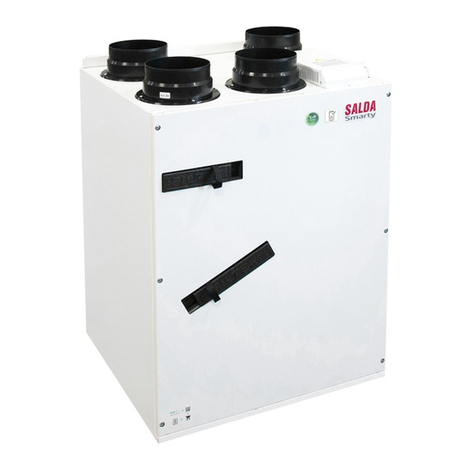
Smarty 2R VE is a residential air handling unit with a high efciency (up to 75 %) rotor heat exchanger with integrated electrical heater. The unit pro-
vides ventilation in the home and takes the heat from the exhausted air. AHU complies with ErP 2018 requirements. The unit is operated by a sepa-
rate remote control panel or though separate MB-Gateway by PC. Remote control panel and MB-Gateway are optional and not included in standard
package.
Smarty 2R VE operates within the limits of the airow diagrams and is suitable for indoor operation only. Required ambient temperatures must be from
-20 oC to +40 oC. For the cold climate zones (air temperatures below -20 oC), optional pre-heater is required.
5
Smarty 2R VE
www.salda.lt
• Unit is designed to operate only indoors.
• It is forbidden to use the unit in potentially explosive environment.
• Unit is designed to supply/extract only clean air (free of chemical compounds causing metal corrosion, of substances aggressive to zinc, plastic and
rubber, and of particles of solid, adhesive and bred materials).
Outdoor - temperature min./max.* [°C] -20 / +40
- humidity [%] 90 Extract - temperature min./max.* [°C] +15 / +40
- max. humidity [%] 60
* Can be used at temperatures below -20 ° C with pre-heater, the power of which is over 600W.
1. Power supply cable collar
2. Extract air lter
3. Exhaust air fan
4. Extract air temperature sensor
5. Control box
6. Rotor
7. Kitchen hood hole
8. Mounting brackets
9. Flange
10. Supply air fan
11. Outdoor air temperature sensor
12. Outdoor air lter
13. Electric heater
14. Rotor engine
15. Hall sensor
16. Galvanized steel casing
17. Kitchen hood ange cover
18. Back door
19. Cable conector cover
20. Front door
1
3
4
5
6
7
8
9
10
11
12
13
14
2
15
16
17
19
20
18
Smarty 3X VER
Smarty 3X VER 3.0
Smarty 3X VEL
Smarty 3X VEL 3.0
Exhaust air
Smarty 3X VER
Smarty 3X VER 3.0
Smarty 3X VEL
Smarty 3X VEL 3.0
Extract air
Smarty 3X VER
Smarty 3X VER 3.0
Smarty 3X VEL
Smarty 3X VEL 3.0
Supply air
Smarty 3X VER
Smarty 3X VER 3.0
Smarty 3X VEL
Smarty 3X VEL 3.0
Outdoor air
Kitchen hood
6
Smarty 2R VE
www.salda.lt
Unplug unit from mains before opening the door (disconnect the power plug from the outlet or if there is a two-pole automatic circuit breaker
installed – disconnect it as well. It is necessary to ensure that it won’t be turned on by third parties) and wait until the full stop of the fans
(for about 2 min.).
Dirt increases air resistance in the lter, therefore less air is sup-
plied into the premises.
It is recommended to change the lters every 3-4 months,
or in accordance to lter timer.
Reset the lter timer in control panel after change of the
lters.
Taking off the lters:
• Open cover.
• Remove the lter.
• Use lters of M5 class.
CAUTION: the heat exchanger can not be used when the
lters are removed!
• Maintenance should be performed only by experienced and trained staff.
• The fan should be inspected and cleaned at least once a year.
• Be sure the fan is disconnected from power source before performing any maintenance or repair.
• Proceed to maintenance and repair after any rotation in the fan is stopped.
• Observe staff safety regulations during maintenance and repair.
• The motor is of heavy duty ball bearing construction. The motor is completely sealed and requires no lubrication for the life of the motor.
• Detach fan from the unit.
• Impeller should be specially checked for buil-up material or dirt which may cause an imbalance. Excessive imbalance can lead to accelerated wear
on motor bearings and noise, vibration.
• Clean impeller and inner housing with mild detergent, water and damp, soft cloth.
• Do not use high pressure cleaner, abrasives, sharp instruments or caustic solvents that may scratch or damage housing and impeller.
• Do not plunge the motor into any uid while cleaning impeller.
• Make sure, that impeller’s balance weights are not moved.
• Make sure the impeller is not hindered.
• Mount the fan back into the unit. Connect the fan to power supply source.
• If after maintenance the fan does not start or stop itself, contact the producer. Malfunction of the fan can be identied according to the pressure in the
system (when pressure switches are connected). When there is a fault in fans’ motor, any separate notice is shown on the control panel.
7
Smarty 2R VE
www.salda.lt
Be sure the unit is disconnected from power source before performing any maintenance or repair.
• Electrical heater does not need to be serviced additionally. It is compulsory to change  lters as described above.
• Heaters have 2 thermal protections: automatically self-resetting, which activates at +50°C and the manually restored, which activates at +100°C.
• After the activation of the manually restored protection, the unit must be disconnected from the power supply. Wait until the heating elements
cool down and the fans stop rotat- ing. After identifying and removing the reason of failure, to start the unit, press the “reset” button. The failure can
be identified only by a qualified professional.
• If necessary, the electric heater can be removed. Disconnect the electrical connector from the heater and remove the heater.
8
Smarty 2R VE
www.salda.lt
• Rotor heat exchanger must be serviced once a year.
• Ensure that the gaps of the heat exchanger are clean, the brushes are not worn, the belt drive is not worn and the clamping nodes of the rotor heat
exchanger are tight.
• Rotor heat exchanger can be easily removed from the unit. The power cord of the motor of the heat exchanger is disconnected. The clamp of rotor
heat exchanger section is released and raised and the heat exchanger is removed.
• Heat exchanger is washed with the warm water and the alkaline solution non-corrosive towards aluminum, or the air stream. Direct contact with the
uid stream is not recommended as the heat exchanger can be affected.
• While cleaning, protect the motor of heat exchanger from entry of moisture and uids.
• After reinstalling the heat exchanger, fasten the heat exchanger section with the clamp. Connect the heat exchanger motor.
• CAUTION: the heat exchanger can not be used when the lters are removed!
Smarty 3X VER
Smarty 3X VER 3.0
Smarty 3X VEL
Smarty 3X VEL 3.0
Exhaust air
Smarty 3X VER
Smarty 3X VER 3.0
Smarty 3X VEL
Smarty 3X VEL 3.0
Extract air
Smarty 3X VER
Smarty 3X VER 3.0
Smarty 3X VEL
Smarty 3X VEL 3.0
Outdoor air
Smarty 3X VER
Smarty 3X VER 3.0
Smarty 3X VEL
Smarty 3X VEL 3.0
Supply air Kitchen hood
The maintenance side can be changed for the ventilation unit, i.e. it can be mounted with the left ambient air inlet or the right ambient air inlet. That
can be implemented by switching over the back door and the front door. The default version of the ventilation unit is right.
Smarty 2R VER
Smarty 2R VEL
9
Smarty 2R VE
www.salda.lt
Installation should only be performed by qualied and trained staff.
• When connecting air ducts, consider the notices indicated on the casing of the unit.
• Before connecting to the air duct system, the connection openings of ventilation unit should be closed.
• Do not connect the bends close to connection anges of the unit. The minimum distance of the straight air duct between the unit and the rst branch of
the air duct in the supply air duct must be 1xD, in air exhaust duct 3xD, where D is diameter of the air duct.
• It is recommended to use the accessories-holders. This will reduce vibration transmitted by the unit to the air duct system and environment.
• Enough space must be left for opening of the maintenance door and lter covers.
• If the installed ventilation unit is adherent to the wall, it may transmit noise vibrations to the premises. Though the level of noise caused by the fans is
admissible, it is recommended to mount the unit at the distance of 400 mm from the nearest wall. If it is not possible, the mounting of the unit is recom-
mended on the wall of the room where the level of noise is not important.
• Ducts are connected to the unit in such way that they could be easily disassembled and the heater could be removed from the unit when performing
service or repair works.
224,5 mm 273,1 mm 100,4 mm
598 mm
276,3 mm 237,7 mm
84 mm
Ø 125 mm
320 mm
116,3 mm 98 mm
105,7 mm
598 mm 320 mm
653 mm
620 mm
653 mm
620 mm
320 mm
598 mm
Ø 175 mm
160 mm
286 mm
10
Smarty 2R VE
www.salda.lt
40 mm
90
90
ca bd
10 mm 10 mm
Mounting on the wall.
a) To reduce the vibration stick the insulating tape on the unit‘s cas-
ing side which touches the wall before mounting the unit on the wall.
b) The unit has to be mounted on the mounting brackets.
c) AHU mounting drawing.
d) After the unit is mounted two wall bracket tabs has to be folded to
90o angle by pliers to avoid the accident fall of the unit.
• Installation works must be performed only by trained and qualied personnel.
• If you have any questions regarding the save installation and use of the product, please contact the manufacturer or the representative.
• Before installing the unit, unscrew the lid a covering the opening for connection of the kitchen hood and remove the middle part of the insulating ring..
• Cut the connecting opening as indicated on the insulation material.
• Carefully remove the lid, which covers the electric connection for the connection of the electrical part of the kitchen hood to the ventilation unit.
• Mount the hood to the ventilation unit. Fasten with self-tapping screws to the designated connection points.
• It is necessary to ensure the tight and reliable connection of the air ducts of the kitchen hood to the ventilation unit and the electrical contact of the
control circuit.
• The subsequent installation of the device is performed according the description in chapter “Mechanic installation”.
• Properties, assembly, control, use and maintenance of the kitchen hood are described in its instalation manual.
Use cooker hood supplied by our company only. Equipment is not tested
with other cooker hoods and company holds no responsibility for malfunc-
tion or failures of the equipment in this case.
11
Smarty 2R VE
www.salda.lt
•Supply voltage to the unit must be connected by a qualied specialist following the manufacturer’s instructions and effective safety instructions.
•The unit’s power network voltage must correspond to electrotechnical parameters of the unit indicated in the technical decal (~230V; 50 Hz).
• The unit’s voltage, power and other technical parameters are provided in the unit’s technical decal (on the unit casing). The unit must be connected
to the voltage plug socket of the grounded power network in compliance with the effective requirements.
• The unit must be earthed according to the rules on installing electrical equipment.
• The start-up and operation of the unearthed ventilation unit is prohibited.
• It is prohibited to use extension wires (cables) and power network plug socket distribution devices.
• Prior to carrying out any ventilation unit installation and connection activities (until its hand-over to the customer), the unit must be disconnected from
the power network.
• Prior to carrying out any ventilation unit maintenance activities, the unit must be disconnected from the power network.
• After installation of the ventilation unit, the power network plug socket must be accessible at any time and disconnection from the power network is
performed through the two-pole circuit breaker (by disconnecting phase pole and neutral).
• The unit must be thoroughly checked against damages (execution, control, measurement nodes) during transportation before it is connected to the
power network.
• The power cable can be replaced only by a qualied specialist upon the evaluation of the rated power and current.
The manufacturer does not assume any liability for personal injuries and property damage due to non-conformance with the
provided instructions.
12
34
12
Smarty 2R VE
www.salda.lt
Subject to technical modication.
W
Exhaust air lter class M5
width L [mm] 270
height H [mm] 86
depth W [mm] 46
model MPL
Supply air lter class M5
width L [mm] 270
height H [mm] 86
depth W [mm] 46
model MPL
Technical data
Heat exchange
- phase/voltage [50 Hz/VAC] ~1/230
- power/current [kW/A] 0,006/0,1
-thermal efciency up to 75%
Heater - power/current [kW/A] 0,6/2,61
Exhaust air fan
- phase/voltage [50 Hz/VAC] ~1/230
- power/current [kW/A] 0,07/0,6
- speed [min-1] 1380
- protection class IP44
- control imput [VDC] 0-10
Supply air fan
- phase/voltage [50 Hz/VAC] ~1/230
- power/current [kW/A] 0,07/0,6
- speed [min-1] 1380
- protection class IP44
- control imput [VDC] 0-10
Total power consumption - power/current [kW/A] 0,75/3,91
Automatic control integrated +
Insulation of walls [mm] 20
Weight [kg] 36
P [W]
P [W]
Δ P [Pa]
stat
v [l/s]
v [m /h]
3
v [l/s]
v [l/s]
v [l/s]
v [m /h]
3
v [m /h]
3
v [m /h]
3
Δ P [Pa]
stat
Δ P [Pa]
stat
Δ P [Pa]
stat
P [W]
P [W]
Δ P [Pa]
stat
v [l/s]
v [m /h]
3
v [l/s]
v [l/s]
v [l/s]
v [m /h]
3
v [m /h]
3
v [m /h]
3
Δ P [Pa]
stat
Δ P [Pa]
stat
Δ P [Pa]
stat
Performance
Power consumption
Supply air
Exhaust air
Specic fan power (SFP)
SFP= x 3600
total power for supply air & exhaust fans kW
air ow m3/h
Temperature efciency
13
Smarty 2R VE
www.salda.lt
Stouch
Ptouch
MBGateway
RR
TA
EKA
NV
PH
Transmitter 1
CO2 or RH
Transmitter 1
CO2 or RH
Separate power supply source
Smarty 3X VER
Smarty 3X VER 3.0
Smarty 3X VEL
Smarty 3X VEL 3.0
Exhaust air
Smarty 3X VER
Smarty 3X VER 3.0
Smarty 3X VEL
Smarty 3X VEL 3.0
Extract air
Smarty 3X VER
Smarty 3X VER 3.0
Smarty 3X VEL
Smarty 3X VEL 3.0
Outdoor air
Smarty 3X VER
Smarty 3X VER 3.0
Smarty 3X VEL
Smarty 3X VEL 3.0
Supply air
Kitchen hood
IV Extract air fan
PV Supply air fan
RR Rotor heat exchanger
PF Filter for supply air (M5)
IF Filter for extract air (M5)
RRotor engine
TL Outdoor air temperature sensor
TA Extract air temperature sensor
PIR Motion detector
DJ Smoke detector
TJ Supply air temperature sensor
CEE7/7 Power cable with plug
PC Personal computer
MBGateway Net module
Stouch Control panel
EKA NV PH* Outdoor air electric preheater
*
* Lower than -20 oC use preheater
Performance
Power consumption
14
Smarty 2R VE
www.salda.lt
Modbus Gateway & web
server MB Gateway
GAUMBGATEWAY001
MB Gateway
Stouch
Remote control
PRGPU51
S-KFF-U
Humidity sensor (duct)
ZAKKT0051
CO2 sensor (room)
ZAKKT0048
S-RCO2-F2
Humidity sensor (room)
ZAKKT0050
S-RFF-U-D-F2
CO2 sensor (duct)
ZAKKT0049
S-KCO2
Front cover white
GNGGAUBT022
Front cover
EKA NV 125-
0,6-1f PH
Electrict preheater
PSIEKANVPH1250.6_1
Cooker hood for white
ZPGKT0041
Cooker hood Front cover
Cooker hood for stainless
steel
ZPGKT0042
Cooker hood
Silencer, heigh 350mm
GSORIRS168_152
Silencer, 350 mm
Silencer, heigh 750mm
GSORIRS168_324
Silencer, 750 mm
Front coover mounting
bracket
GNGKRON17
Mounting bracket
Front cover stainless steel
GNGGAUBTSS1
Front cover
Remote control panel
PRGPU081
Ptouch CM24-F-L
Actuator for damper
ZAKP0029
Panel lter
GKOFIL0016
MPL
(F7/F7)
MPL
(M5/M5)
Panel lter
GKOFIL0015
15
Smarty 2R VE
www.salda.lt
MCB V1.0
Controler
ZED00985
Hall
H1A-D12P24-1
Hall sensor
PJUT0006
TJ
Supply air temperature
sensor
PJUT0063
TA/TL
Extract/ Outdoor air tem-
perature sensor
PJUT0062
Door
Smarty 2R VE durys
GNGO0061
Rotor box motor
ZVAR0133
Rotor motor
Rotor box belt
GNGO0062
Rotor belt Fan
Fan supply/exhaust
GPUVRA009
Rotor box
GPURSD085
Rotor box
16
Smarty 2R VE
www.salda.lt
Functions and logic of the control board are designed on the basis of DIN 1946-06 and EN 12098-3 standards.
System modes:
stand-by in this mode the system stops for the limited time period under the settings of standby mode blocking
function;
building protection the mode is intended to protect the building from moisture accumulation. In this mode the system
works at speed 1. By default, temperature is not controlled, but under request it is possible to specify
the desired temperature;
economy the mode is intended to save energy when there are no people in the premises. In this mode the sys-
tem works at speed 2. By default, temperature is controlled (indicating the desired temperature), but
under request it is possible to disable the temperature control;
comfort the mode is intended for ventilation of the premises when there are people inside. In this mode the sys-
tem works at speed 3. By default, there temperature is always controlled, it is set in the main window.
Versions and working hours of the system:
Software and its conguration versions can be monitored in service menu. Specic conguration version for each unit is installed on the production
line. Working hours of the unit are displayed as well. Working hours calculate when the fan is running.
System state
Information for the user about the current state of the system. Possible system states and their descriptions:
State Description
Stand-by mode System operates in Stand-by mode
Building protection mode System operates in Building protection mode
Economy mode System operates in Economy mode
Comfort mode System operates in Comfort mode
Emergency run System operates in Emergency run
Preparing System is preparing for operation
Opening dampers Dampers are being opened
BOOST function activated Activated BOOST function
Cooling heaters Electric heaters are being cooled before stopping the fans
Closing dampers Dampers are being closed
Critical alarm Critical fault, system is stopped
Fire alarm Fire alarm protection is activated from external contact.
MCB control board can be controlled with:
Ptouch remote control panel Stouch remote control panel MB - GATEWAY web application
Ptouch remote control panel controllable all the
functions described in the technical documenta-
tion.
General description of the functions and instruc-
tion of the user’s settings are described below.
Download instructions for adjuster and service
settings: http://salda.lt/en/products/category/ven-
tilation/;
Stouch remote control panel c o n t r o l l a b l e
temperature, speed, air lter timer, BOOST
function settings, display of the faults.
General description of the functions and in-
struction of the user’s settings are described
below. Download instructions for adjuster and
service settings: http://salda.lt/en/products/cat-
egory/ventilation/;
in MB-GATEWAY web application
controllable all the functions described in the
technical documentation.
General description of the functions. Down-
load instructions of the user’s, adjuster’s and
service settings: http://salda.lt/en/products/
category/ventilation/. The software upgrade
via MicroSD card.
17
Smarty 2R VE
www.salda.lt
Heat exchanger frost protection activated Anti-frost protections of the heat exchanger is activated
Change lters Warning about dirty lters. Pressure relay or lter timer
Room RH 3 days average is lower than 30%.
Limiting 3 speed.
Activated protection from dryness. Room RH 3 days average is lower than 30%. Limiting air ow.
Indications of functions, warnings and alarms
Information for the user about active functions, alarms or warnings. Meaning of the indications:
System mode is activated from the external contact
Fans speed is activated form the external contact
Reduction of fans speed according the temperature
Reduction of CO2 level
Active circulation pumps maintenance check up
Heating season (winter)
Cooling season (summer)
Stand-by mode blocking
Active night cooling function
Fans speed reduction
Automatic operation of the system is blocked. This function
is activated during service maintenance.
Active holiday schedule. To change the mode it is neces-
sary to stop the function or change the holiday date.
These functions (in sequence as set out) change the modes of the system:
1. blocking of Stand-by mode stand-by mode can be blocked under preferable parameters.
2. holiday schedule user cannot change the mode. System informs about active mode of the holiday schedule. To
stop the function it is necessary to change or disable the period of the holiday;
3. user‘s manual mode selection user can change the modes;
4. active mode form external contact user can override by changing system mode;
5. weekly schedule system operates in mode under weekly schedule, the user can change the current mode manu-
ally. System will inform about the next change of the mode under the schedule;
If any of the above mentioned functions has changed it’s state into Stand-by mode, system checks if the mode is not blocked at the current time. If the
mode is blocked, the system returns to previous mode.
Saving settings after power cut
After a power cut the unit continues operation at the speed and temperature set before the accident.
Smooth temperature control during fans speed reduction
This functions saves the energy at the change of the air ow. It is active when the fans are controlled by percentage, because PID controllers does this
automatically when controlling by the air ow or pressure. If the user sets a higher air ow, this function is gradually starting to increase air ow and
when getting closer to the set value gradually reduces the speed, this way temperature control function experiences less stress, less energy is being
wasted. If the user reduces the air ow, the system stops the coolers and heaters in order to avoid heat/cold wave and gradually changes the air ow.
After the reduction of air ow heaters and coolers continue to operate on demand.
Air ow control
Indication of the air ow in percentage, pressure or air quantity depending on the system conguration.
PID controllers adjusting
The coefcients of all the PID controller are adjusted. The quantity of the coefcients depends on the system conguration.
Manual control
Manual control of the components function activates/deactivates components manually. Components are controlled by digital and analog outputs.
Analogue outputs are controlled in percent, while digital - “on/off”. By default, all components are specied as “Auto” state, which means that the com-
ponent is controlled under the ventilation logics.
18
Smarty 2R VE
www.salda.lt
Date and time setting
For the proper operation of schedule, events, and heating season functions it is necessary to set the date and time.
Weekly schedule
Weekly schedule consists of 10 weekly events. They can be added, deleted, activated and deactivated. Time, mode and day of the week are set for
one event.
Holiday schedule
The unit operates at one specied mode during the holiday period. The user can check and change the specied holiday period. The active mode of
this function cannot be changed by any other function except for security functions.
Heating season
To protect some of the system parts from cold outdoor air during the cold season it is recommended to keep the unit in operation mode, it can be done
by setting the heating season function which blocks the turn off function of the unit. Water heaters must be turned on during entire cold season period.
The heating season can be set up:
• manually;
• by date;
• by average three-day outdoor air temperature. Average temperature is being calculated only when outdoor air preheater is turned off.
BOOST
BOOST function is used for intensive ventilation of the premises. This function activates the maximum air ow (4th speed). Intensive ventilation must
be temporary, i.e. there must be nite condition (e. g. CO2 limit, time period). The reason for the restriction - protection against dryness. High air ow
reduces humidity and dry air harmful to health.
Night cooling
This function is used for energy saving. Cool night air is used to cool the indoor air in the morning. Function actives for a specied time when the
outside and the room air temperature is higher than the “SetPoint” - 10C (default setting) and the room air temperature is at least 2 degrees warmer
than the outside air. In other cases, the function is inactive. When the function is active, fan operates at speed 3 and heat exchanger cools the air till
the set air temperature limit “SetPoint“.
Event history
The system records 50 recent events (faults, warnings, re damper testing results, etc.). Event description and time is saved in the history.
Filter timer setting
Air lter timer informs the user about time to change the lters. After changing the lters timer should be reset. The user can always see how many
days are left until the next change of the lters. The time is calculated only when the fans are operating.
Protection from dryness
This function protects the premises from dryness. If the function is active, it calculates three days room extract air humidity average. If the average is
lower than 30% in comfort mode, fans start to operate at speed 2. The user is informed about the active protection function and reduced air ow. If the
humidity average is higher than 30% function is deactivated manually, fans star to operate at speed 3 in comfort mode.
Supply air temperature control and compensation
Optional temperature control by supply or extract air temperature. Indication of the permissible minimum and maximum supply air temperature limits
and compensation percent.
Stand-by mode blocking
This function protects the system against impermissible turning off of the unit. Allowed period for turn off in 12 hours should be indicated. If the turn off
is blocked and the system is off, the system calculates the time and informs the user about the remaining time. Possible function modes:
• Never - always allow always turn off;
• Always – always block turning off;
• On Heating Season - block turning off during the heating (winter) season;
• On Cooling Season - block turning off during cooling (summer) season.
System mode from external contact
This function activates the desired mode from the external contact. Type of signal, which will be fed to the input, should be indicated. Possible types
of signals:
• None- not used;
• Push – by impulse on/off;
• On/Off – On/Off by the switch;
• PIR – by PIR sensor.
Fans speed from external contact
This function activates/de activates boost function or desired fans speed combination from external contact. Type of signal, which will be fed to the
input, and its control options should be indicated. Possible signal types and combinations:
• None - not used;
• CUSTOM push - On/Off by the impulse signal;
• CUSTOM On/Off – by the switch On/Off;
• BOOST push – On/Off by the impulse or switch.
CO2 reduction function
This function helps to maintain proper indoor air quality. Indicate the desired level of CO2 and permissible overrun limit. When CO2 exceeds the permis-
sible limit, the CO2 reduction is activated increasing air ow, the information displayed for the user. When CO2 level reaches a set value, the function
19
Smarty 2R VE
www.salda.lt
of CO2 reduction is switched off.
Air ow reduction by the temperature
If the supply air temperature is more important than the air ow, it is possible to turn on air ow reduction depending on the temperature function. If all
the heating power is consumed on the desired temperature support and the desired result is not reached, then reduction of the air ow starts in order
to support enough power for required temperature maintenance.
Supply air heater
Supply air heaters are designed to heat the supplied air in addition, when a heat exchanger heating power is not enough. The heater is controlled by
the PID controller according to the data of set and supply air temperature sensor. One supply air heater can be connected to the system. It can be
either electrical or water. Supply air heater identication versions:
• None;
• Electrical 0..10;
• Electrical On/Off;
• Hydraulic.
Electrical heaters cooling
If an electric heater had been used and system is required to stop the fan, then before stopping the fan heater is turned off and cooled by blowing for
given time period. The user is informed about active heaters cooling function.
Dampers control
Before starting the fans dampers are opened, when fans are stopped dampers are closed. It is possible to congure damper opening/closing time.
By default 30 s.
• Supply/Extract air damper – None, On/Off, Open/Close - open before starting the fan and close when fans are stopped;
• Recirculation damper – Disabled/Enabled – used in heat exchangers anti-frost protection function;
• Fire damper – None, One switch, Two switches.
If On/Off or Open/Close damper type is specied, it is necessary to indicate the opening time.
Fire dampers can be tested either manually or automatically every specied date range. Test results are stored in the events history. The user can
specify the hour of damper testing (user settings), air ow is stopped during the testing.
The enforced stop function
Used to block all the control algorithms. Helpful for service maintenance.
Cold-Heat recuperation
This function controls heat exchanger. Heat recovery takes place when the extracted indoor air is warmer than the outdoor air. Plate heat exchanger
power is controlled with bypass damper. When the damper is closed, full capacity of the heat exchanger is used. After opening the damper the capac-
ity of the heat exchanger is being reduced.
Chimney sweep function
This function works by adjusting the fans speed from external contact function, an external contact is connected to the replace door switch. When
replace door is opened the exhaust air fan is stopped and supply air fan is started at full capacity. This creates overpressure in the room for better
traction of smoke through the chimney.
Default parameters resetting
If the setting of the parameters caused incorrect operation of the system, it is always possible to restore the default settings. User settings, such as
weekly schedule, won’t be changed by restoring to default settings.
Filter protection:
timer limit – air lters time limit is set in service menu. Reset the lters timer after the change of the lters. User can also reset the lters timer. (antras
sakinys kartojasi “air lters time limit is set in service menu”). The maximum permitted time - 1 year. Time calculates only when fans are in operation;
press rely type – it is indicated if the press rely is used for lter protection. Possible combinations:
• None;
• Supply;
• Extract;
• Both.
Fans protection by RPM
If fans have “Tacho” outputs it is possible to identify fan failure by their rotational speed. If the system gives a signal for fans to rotate, but they do not,
the protection is activated, the system stops and displays a warning.
Supply air temperature protection
This function protects against undesirable supply air temperature. Minimal and maximal supply air temperature, permissible time and protection ac-
tions are indicated. That protection is limited by the user‘s as well as other functions supply air temperature settings. By default, the minimum permitted
supply air temperature is + 16.5 °C, and maximum + 35.0 °C. If the supply air temperature drops below 5 oC, equipment stops despite these protection
settings!
Fire protection from external contact
Normal contact state NC/NO and actions in case of re are indicated:
• Stop system;
• Boost supply air;
• Boost extract air;
• Boost supply and extract air.
Fans protection by integrated protection
This protection is active when fans protection function by RPM is off. The fan protection input is active, the system stops.
20
Smarty 2R VE
www.salda.lt
Electric heaters thermo protection
Electric heater may have two protections. One is automatic, the other manual. Automatic protection automatically shuts down when the heater is
cooled, manual protection must be turned off by pressing the switch which is on the heater.
When the protection activates the heater and its power circuit turns off, the warning is displayed. Minimal shut-off time - 5 minutes. When the protection
recovers, the warning is no longer displayed.
Temperature sensor failure protection
Ability to specify what should be done for each temperature sensor failure event.
Available Options:
• unit is stopped and a warning is displayed;
• the unit is working in emergency mode and the warning is displayed
The system informs the user about the failure warnings and alarms. Alarms are cancelled automatically, while warnings must be cancelled manually. It
is recommended the warnings to be cancelled by a specialist after the detection of the reason for the alert. If at least one warning is active, the system
stops and external fault indication is being activated.
Possible alarms and warnings:
Alarms and warnings list
Alarm! Fireplace protection activated
Warning! Dryness protection activated
Warning! Plate heat exchanger frost protection activated
Alarm! Plate heat exchanger frost protection. System stopped.
Alarm! Plate heat exchanger frost protection (pressure relay). System stopped.
Alarm! Hydraulic heater frost protection. System stopped.
Warning! Too low supply temperature
Warning! Too high supply temperature
Alarm! Too low supply temperature. System stopped.
Alarm! Too high supply temperature. System stopped.
Alarm! Change supply air lter (pressure relay). System stopped.
Alarm! Change extract air lter (pressure relay). System stopped.
Warning! Change supply and extract lters.
Alarm! Change supply and extract lters. System stopped.
Warning! Supply air temperature sensor failure. Emergency run.
Warning! Extract air temperature sensor failure. Emergency run.
Warning! Exhaust air temperature sensor failure. Emergency run.
Warning! Fresh air temperature sensor failure. Emergency run.
Warning! Hydraulic heater water temperature sensor failure. Emergency run.
Warning! Hydraulic preheater water temperature sensor failure. Emergency run.
Warning! Hydraulic cooler water temperature sensor failure. Emergency run.
Warning! Control box temperature sensor failure. Emergency run.
Alarm! Supply air temperature sensor failure. System stopped.
Alarm! Extract air temperature sensor failure. System stopped.
Alarm! Exhaust air temperature sensor failure. System stopped.
Alarm! Fresh air temperature sensor failure. System stopped.
Alarm! Hydraulic heater water temperature sensor failure. System stopped.
Alarm! Hydraulic preheater water temperature sensor failure. System stopped.
Alarm! Hydraulic cooler water temperature sensor failure. System stopped.
Alarm! Control box temperature sensor failure. System stopped.
Alarm! Fire damper test failed
Alarm! Heater manual protection. System stopped.
Warning! Heater automatic protection
Alarm! Preheater manual protection. System stopped.
Warning! Preheater automatic protection
Alarm! Supply fan failure

Other manuals for Smarty 2R VE

1

Other Salda Fan manuals

Salda AMBERAIR User manual

Salda

Salda AMBERAIR User manual

Salda VSA 220 M 3.0 User manual

Salda

Salda VSA 220 M 3.0 User manual

Salda RIRS 700VE EKO 3.0 User manual

Salda

Salda RIRS 700VE EKO 3.0 User manual

Salda RIS 400HE 3.0 Instruction manual

Salda

Salda RIS 400HE 3.0 Instruction manual

Salda VKA 125 EKO User manual

Salda

Salda VKA 125 EKO User manual

Salda KF T120 EC Series User manual

Salda

Salda KF T120 EC Series User manual

Salda VSA 3.0 Series Guide

Salda

Salda VSA 3.0 Series Guide

Salda RIS 1200HE/HW EKO 3.0 User manual

Salda

Salda RIS 1200HE/HW EKO 3.0 User manual

Salda RIRS 3500VE-VW EKO 3.0 User manual

Salda

Salda RIRS 3500VE-VW EKO 3.0 User manual

Salda AKU 500x250 EKO User manual

Salda

Salda AKU 500x250 EKO User manual

Salda RIS 400PE EKO 3.0 User manual

Salda

Salda RIS 400PE EKO 3.0 User manual

Salda Smarty 4X V User manual

Salda

Salda Smarty 4X V User manual

Salda RIRS 350 PE EKO 3.0 User manual

Salda

Salda RIRS 350 PE EKO 3.0 User manual

Salda RIS 700PE 3.0 EKO 3.0 User manual

Salda

Salda RIS 700PE 3.0 EKO 3.0 User manual

Salda RIS 1200PE/PW EKO 3.0 User manual

Salda

Salda RIS 1200PE/PW EKO 3.0 User manual

Salda RIRS 5500HE EKO 3.0 User manual

Salda

Salda RIRS 5500HE EKO 3.0 User manual

Salda RIRS 400HE/HW EKO 3.0 User manual

Salda

Salda RIRS 400HE/HW EKO 3.0 User manual

Salda RIRS 1200HE EKO 3.0 User manual

Salda

Salda RIRS 1200HE EKO 3.0 User manual

Salda RIRS 3500VE-VW EKO 3.0 User manual

Salda

Salda RIRS 3500VE-VW EKO 3.0 User manual

Salda SMARTY XV Series User manual

Salda

Salda SMARTY XV Series User manual

Salda AKU 125 M User manual

Salda

Salda AKU 125 M User manual

Salda KF T120 Series User manual

Salda

Salda KF T120 Series User manual

Salda AKU 500x250 EKO User manual

Salda

Salda AKU 500x250 EKO User manual

Salda AKU Series Guide

Salda

Salda AKU Series Guide

Popular Fan manuals by other brands

Kichler Lighting Lucian II 330241 instruction manual

Kichler Lighting

Kichler Lighting Lucian II 330241 instruction manual

Teka Caremaster BGIA operating instructions

Teka

Teka Caremaster BGIA operating instructions

Fanimation FP7902BN owner's manual

Fanimation

Fanimation FP7902BN owner's manual

Anslut 013883 operating instructions

Anslut

Anslut 013883 operating instructions

Hydor HCF Installation and maintenance instructions

Hydor

Hydor HCF Installation and maintenance instructions

TriangleTube instinct SOLO 110 manual

TriangleTube

TriangleTube instinct SOLO 110 manual

S-BOL TF-A03 instruction manual

S-BOL

S-BOL TF-A03 instruction manual

Sanuvox S1000FX-GX Installer's instructions

Sanuvox

Sanuvox S1000FX-GX Installer's instructions

McQuay MFU-C product manual

McQuay

McQuay MFU-C product manual

Brink Renovent Excellent 180 installation instructions

Brink

Brink Renovent Excellent 180 installation instructions

Melchioni MF 2404T40 user manual

Melchioni

Melchioni MF 2404T40 user manual

Viessmann VITOVENT 300 Operating Instructions for the System User

Viessmann

Viessmann VITOVENT 300 Operating Instructions for the System User

Casablanca M8501-01 instructions

Casablanca

Casablanca M8501-01 instructions

commercial cool CCF55P60 user manual

commercial cool

commercial cool CCF55P60 user manual

Faro Barcelona Cies installation guide

Faro Barcelona

Faro Barcelona Cies installation guide

Plymovent FUA-1300 user manual

Plymovent

Plymovent FUA-1300 user manual

Munters EM52 Manual for use and maintenance

Munters

Munters EM52 Manual for use and maintenance

Panasonic FV-08-11VFL5E Service manual

Panasonic

Panasonic FV-08-11VFL5E Service manual

manuals.online logo
manuals.online logoBrands
  • About & Mission
  • Contact us
  • Privacy Policy
  • Terms and Conditions

Copyright 2025 Manuals.Online. All Rights Reserved.