Salda AVS 125 Guide

AVS/SVS/SVS V
EN MOUNTING AND INSTALLATION INSTRUCTION 2
LT MONTAVIMO IR INSTALIAVIMO INSTRUKCIJA 26
DE MONTAGE- UND INSTALLATIONSANLEITUNG 74
RU ИНСТРУКЦИЯ ПО УСТАНОВКЕ И МОНТАЖУ 146
FR MANUEL DE MONTAGE ET D’INSTALLATION 26
IT MANUALE INSTALLAZIONE E MONTAGGIO 32

AVS/SVS/SVS V v2019.032 | EN
1. SYMBOLS AND MARKING
Product name
Weight 00,00 kg
Made in Šiauliai, Lithuania
SKU000000
LN: gu634612
2019.01.01
1
4
5
2
6
3
AS THE HEAT EXCHANGER IS NOT ENTIRELY
DRAINABLE, MAKE SURE THAT IT IS FILLED WITH
A SUITABLE ANTIFREEZING MIXTURE IN CASE
OFFREEZING RISK.
Figure 1.1 - Technical label
1 - Logo; 2 - Product code (SKU); 3 - Product name; 4 - Technical data; 5 - Lot number and production date; 6 - Production place.
2. GENERAL INFORMATION
• Before installing the unit read the entire information provided in this document.
• Installation of the unit shall only be performed by trained and qualied personnel aware of installation of such type of units, inspection, mainte-
nance and tools required for installation works.
• If the provided information is unclear or any doubts arise regarding safe installation and operation, please contact the manufacturer or his rep-
resentative.
• The unit shall be operated only under the below listed conditions.
• It is strictly forbidden to use the unit for non-designed purposes or in contradiction to the specied working conditions without written permission
of manufacturer or his representative.
• The manufacturer or his representative shall be notied about any fault, including description of the fault and data specied on the manufacturer’s
label.
• Any repair or dismantle of the unit in case of fault is forbidden without previous written permission of manufacturer or his representative.
• Dismantling, repair or modication of the unit shall be performed only upon previous written consent from manufacturer or his representative.
3. TRANSPORTATION AND STORAGE
• All units are packed in the factory to withstand regular conditions of transportation.
• Upon unpacking, check the unit for any damages caused during transportation. It is forbidden to install damaged units!!!
• The package is only for protection purpose!
• While unloading and storing the units, use suitable lifting equipment to avoid damages and injuries. Do not lift units by holding on power supply
cables, connection boxes, air intake or discharge anges. Avoid hits and shock overloads. Before installation units must be stored in a dry room
with the relative air humidity not exceeding 70% (at +20°C) and with the average ambient temperature ranging between +5°C and +30°C. The
place of storage must be protected against dirt and water.
• The units must be transported to the storage or installation site using forklifts.
• The storage is not recommended for a period longer than one year. In case of storage longer than one year, before the installation it is necessary
to verify whether the bearings of fans and motor rotate easily (turn the impeller by hand) and if the electric circuit insulation is not damaged or
the moisture is accumulated.
4. DESCRIPTION
• Used in ventilation systems.
• Heaters are made of copper tubes and aluminium plates. The housing is made of galvanized steel.
• The service panel is easily removed after unscrewing 4 bolts. With the cover removed, the heater can be cleaned and inspected.
• Easy to mount.
• Suitable for operation indoor environment.
The purpose of the unit is: heating of clean air. The unit is used in clean air ventilation and conditioning systems.
5. OPERATING CONDITIONS
• Unit is designed for indoor use only at temperature between +5°C and +40°C and relative humidity not exceeding 70%.
• It is forbidden to use the units in potentially explosive environment.
• Unit is designed for warming up only clean supply air (free of chemical compounds causing metal corrosion, of substances aggressive to copper,
zinc, plastic and rubber, and of particles of solid, adhesive and bred materials) in ventilation and conditioning systems.
• Minimum and maximum permissible air ow temperature between +5°C and +40°C.
• Maximum outside humidity 90%.
• Water quality indicators must not exceed the specied values: total amount of chlorine and sulfur ions – up to 150 mg/l (in the case of copper
pipes - up to 50 mg/l), oxygen up to 0,1 mg/l; water acidity (pH) must hold at 8,0–9,5; total hardness up to 4.0 mval/l.
• Before using the products manufactured or supplied by the company, the clients must ensure the products are compatible with the selected
environment.

AVS/SVS/SVS V v2019.03 EN | 3
6. SAFETY PRECAUTIONS
• Do not use the unit for purposes other than its’ intended use.
• Do not disassemble or modify the unit in any way. Doing so may lead to mechanical failure or injury.
• Use special clothing and be careful while performing maintenance, and repair jobs - edges of the components’ casings may be sharp and cutting.
• Do not place or operate unit on unsteady surfaces and mounting frames.
• Mount the unit rmly to ensure safe operating.
• Never use this unit in any explosive or aggressive elements containing environment.
7. MOUNTING
• Installation works shall be performed only by trained and qualied personnel.
• Remove safety cover before starting mounting procedures (pic. S1).
• Coils can be mounted only horizontally.
• The unit shall be installed rmly and tightly to ensure safe operation.
• The unit shall be mounted on a at surface so that the product is not leaning.
• Installation shall be performed in such manner that the weight of the air duct system and its components would not overload the ventilation unit.
• Enough space must be left during installation for opening of the maintenance door of the unit.
• When connecting water heater, the weight of the water pipes and thermal tensions should not be transferred on the heater branches.
• When mounting threaded connections of supply pipes and heaters, use two spanners (pic. S3).
• Pipes are connected to the heater in such way that they could be easily disassembled and the heater could be removed from the unit casing
when performing service or repair works.
• Pipes with supply and return heat carriers must be connected in such way that the heater would work in the opposite direction for the air ow. If
the heater works using the same directions, the mean temperature dierence decreases which aects the heater eciency (pic. S2).
Max. operating pressure: 1,0 MPa;
Max. operating temp.: 100 °C.
S1: S2:
Water in
Water out
Inlet air ow
Water in
Water out
Inlet air ow
S3:
bcd
ae
8. MAINTENANCE
Checking:
• Check if connections between the unit and ducts are hermetical.
• Check performance of thermal circulation. Temporary increase water temperature for this.
• Check tightness of water supply system.
Cleaning:
• Disconnect and remove heater.
• If heater is soiled - use vacuum cleaner or airow blast.
• In case of heavy choking - clean with warm water and mild detergent solution.
• Check tightness of tubes of disconnected and removed heater with high-pressure air.

AVS/SVS/SVS V v2019.034 | EN
9. INSPECTION OF THE VENTILATION SYSTEM
In order to ensure the ecient operation of the ventilation unit, the inspection of the entire ventilation system, i.e. inspect if the air collection grating
or the units for the air supply to the room are not contaminated, must be carried out once a year. Inspect if the air duct system is not contaminated.
Clean or replace these units if necessary.
10. DIMENSIONS
d
d
d
Figure 10.1 - AVS dimensions
AVS A B C a a1 b ød L øD m
[mm] [mm] [mm] [mm] [mm] [mm] [mm] [mm] [mm] [kg]
125 214 190 333 114 22 138 21,34 287 125 6,0
160 289 265 304 115 20 213 21,34 361 160 8,2
200 289 265 304 115 20 213 21,34 361 200 8,5
250 364 395 342 110 29 283 21,34 531 250 12,5
315 439 460 342 110 30 363 21,34 611 315 16,0
400 514 550 367 110 29 383 26,67 691 400 20,0
500 599 730 367 109 32 463 26,67 846 500 28,0
Figure 10.2 - SVS/SVS V dimensions
SVS A B C D E F ød m
[mm] [mm] [mm] [mm] [mm] [mm] [mm] [kg]
500x250-2 500 250 520 270 540 290 3/4
500x250-4 500 250 520 270 540 290 3/4
600x300-2 600 300 620 320 640 340 3/4
600x300-4 600 300 620 320 640 340 3/4
600x350-2 600 350 620 370 640 390 3/4
600x350-4 600 350 620 370 640 390 3/4
700x400-2 700 400 720 420 740 440 1
700x400-4 700 400 720 420 740 440 1
800x500-2 800 500 820 520 840 540 1
800x500-4 800 500 820 520 840 540 1
SVS V A B C D E F ød m
[mm] [mm] [mm] [mm] [mm] [mm] [mm] [kg]
500x250 H2 500 250 520 270 540 290 21,7
600x300 H2 600 300 620 320 640 340 21,7
900x300 H2 900 300 920 320 940 340 21,7

AVS/SVS/SVS V v2019.03 EN | 5
11. DECLARATION OF CONFIMITY
Manufacturer
SALDA, UAB
Ragainės g. 100
LT-78109 Šiauliai, Lithuania
Tel.: +370 41 540415
www.salda.lt
Hereby conrms that the following products - Air handling units:
AVS/SVS/SVS V*
(where by „*“ indicates possible unit design size and modication)
Provided it was delivered and installed in the facility in accordance with the included installation instructions, comply
with all applicable requirements in the following directives:
Machinery Directive 2006/42/EC
Pressure Equipment Directive 2014/68/EU
The following harmonized standards are applied in applicable parts:
LST EN ISO 12100:2011 - Safety of machinery - General principles for design - Risk assessment and risk reduction.
LST EN 378-2:2008+A2:2012 - Refrigerating systems and heat pumps - Safety and environmental requirements - Part 2: Design, construction,
testing, marking and documentation.
Should any alterations be made in the products, this declaration will no longer apply.
Notied body: VšĮ Technikos priežiūros tarnyba, Naugarduko g. 41, LT – 03227 Vilnius, Lithuania, identication number 1399.
Quality: Salda UAB activities are in line with the international quality management system standard ISO 9001:2015.
Date 2019-02-01
Giedrius Taujenis
Director product development

AVS/SVS/SVS V v2019.036 | EN
12. WARRANTY
1. All equipment manufactured in our factory is checked in operating conditions and tested befor delivery. Test protocol is supplied together with
the unit. The equipment is shipped in good working order and condition to the direct client. The unit is warrantied for the period of two years from
the invoice date.
2. If equipment is found to have been damaged during transportation, a claim should be made against carrier, as we assume no responsibility for
such damage.
3. This warranty does not apply:
3.1. when transportation, storage, installation and maintenance instructions of the unit are violated;
3.2. when the equipment is improperly maintained, mounted - inadequate maintenance;
3.3. when the equipment without our knowledge and permission has been upgraded or unskilled repairs were made;
3.4. when the unit was used not for its original purpose.
3.5. Company SALDA UAB is not responsible for potential loss of property or personal injury in cases where AHU is manufactured without a
control system and the control system will be installed by the client or third parties. The manufacturer’s warranty does not cover devices that
will be damaged by installing the control system.
4. This warranty does not apply at these malfunction cases:
4.1. mechanical damage;
4.2. damage caused by entering outside objects, materials, liquids;
4.3. damage caused by natural disaster, accident (voltage change in the electricity network, lightning, etc..).
5. The company assumes no liability for its products either directly or indirectly damage, if the damage is caused by failure to comply with instal-
lation and mounting regulations, deliberate or careless users or third-party behavior.
These conditions are readily discernable when the equipment is returned to our factory for inspection.
If the direct client determines that equipment is found to be faulty, or a breakdown occurred, he should inform the manufacturer within ve working
days and deliver the equipment to manufacturer. Delivery costs should be covered by customer.
Manufacturer reserves the right to change this technical passport any time without prior notice, if some typographic
errors or inaccurate information is found, as well as after improving the apps and/or the devices. Such changes will be
included in the new issues of the technical passport. All illustrations are just for information and thus may dier from the
original device.
12.1. LIMITED WARRANTY COUPON
Warranty term
24 months*
I received complete package and technical manual of the product ready for usage. I have read warranty terms and conditions and agree with them:
..........................................................................................................................................................................
Customer’s signature
*refer to WARRANTY CONDITIONS
Dear User, we appreciate your choice and do hereby guarantee that all ventilation equipment manufactured by our Company is inspected and
thoroughly tested. An operational and high-quality product is sold to the direct buyer and shipped from the territory of the factory. It is provided with
a 24-month warranty since invoice issue date.
Your opinion is important to us, thus we always look forward to hearing your comments, feedback, or suggestions regarding technical and opera-
tional characteristics of the Products.
In order to avoid any misunderstandings, please read the instructions for installation and operation of the product as well as other technical docu-
ments of the product carefully. The number of the Limited Warranty Coupon and serial number of the product specied on the silver identication
sticker attached to the housing must match.
The Limited Warranty Coupon shall be valid provided that the seller’s stamps and records are clear. It is prohibited to change, delete, or rewrite
the data specied on it in any manner – such a coupon shall be invalid.
With this Limited Warranty Coupon the manufacturer conrms one’s obligations to implement the imperative requirements established by eective
laws on protection of consumer rights in the event of identication of any defects of the products.
The manufacturer reserves the right to refuse provision of free warranty servicing in cases when the warranty conditions listed below are disre-
garded.

AVS/SVS/SVS V v2019.03 LT | 7
1. SIMBOLIAI IR ŽYMĖJIMAI
Product name
Weight 00,00 kg
Made in Šiauliai, Lithuania
SKU000000
LN: gu634612
2019.01.01
1
4
5
2
6
3
AS THE HEAT EXCHANGER IS NOT ENTIRELY
DRAINABLE, MAKE SURE THAT IT IS FILLED WITH
A SUITABLE ANTIFREEZING MIXTURE IN CASE
OFFREEZING RISK.
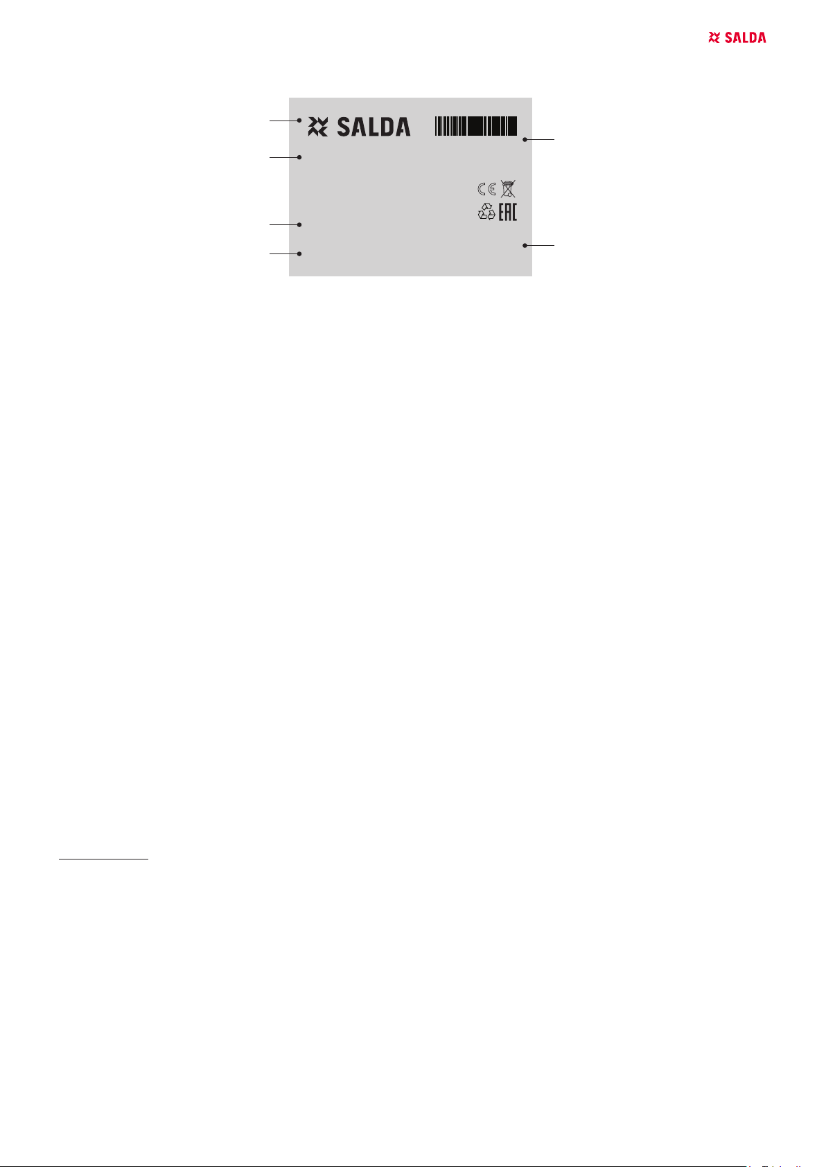
Pav. 1.1 - Techninislipdukas
1 - Logotipas; 2 - produkto kodas (SKU); 3 - produkto pavadinimas; 4 - techniniai duomenys; 5 - gamybos užsakymo numeris ir pagaminimo
data; 6 - produkto pagaminimo vieta.
2. BENDRA INFORMACIJA
• Prieš montuojant įrenginį būtina perskaityti visą šiame dokumente pateiktą medžiagą.
• Įrenginio montavimą gali atlikti tik apmokytas ir kvalikuotas personalas, susipažinęs su tokio tipo įrenginių montavimu, jų patikra, aptarnavimu
ir reikalingais darbo įrankiais, montavimo darbams atlikti.
• Jei pateikta medžiaga yra neaiški, ar kyla abejonių dėl saugaus montavimo ir naudojimo, kreipkitės į gamintoją ar jo atsovą.
• Įrenginys gali dirbti tik žemiau išvardintose sąlygose.
• Griežtai draudžiama naudoti įrenginį ne pagal paskirtį ar ne pagal numatytas darbo sąlygas, negavus tam raštiško gamintojo arba atstovo leidimo.
• Atsiradus gedimui, būtina pranešti gamintojui ar jo atstovui, apibūdinti gedimą bei pateikti duomenis, nurodytus gaminio lipduke.
• Atsiradus gedimams, draudžiama remontuoti, ardyti įrenginį, prieš tai negavus gamintojo ar jo atstovo raštiško leidimo.
• Įrenginio ardymą, remonto darbus ar modikavimą galima atlikti tik gavus raštišką gamintojo arba jo atstovo sutikimą.
3. TRANSPORTAVIMAS IR SAUGOJIMAS
• Visi įrenginiai yra supakuoti gamykloje taip, kad atlaikytų normalias pervežimo sąlygas.
• Išpakavus įrenginį patikrinkite, ar transportuojant jis nebuvo pažeistas. Pažeistus įrenginius montuoti draužiama!!!
• Pakuotė yra tik apsaugos priemonė!
• Iškraudami ir sandėliuodami įrenginius, naudokite tinkamą kėlimo įrangą, kad išvengtumėte nuostolių ir sužeidimų. Nekelkite įrenginių už mai-
tinimo laidų, pajungimo dėžučių, oro paėmimo arba šalinimo anšų. Venkite sutrenkimų ir smūginių perkrovų. Įrenginius sandėliuokite sausoje
patalpoje, kur santykinė oro drėgmė neviršyja 70% (esant +20°C), vidutinė aplinkos temperatūra - tarp +5°C ir +30°C. Sandėliavimo vieta turi
būti apsaugota nuo purvo ir vandens.
• Į sandėliavimo ar montavimo vietą įrenginiai yra gabenami keltuvais.
• Nepatariame sandėliuoti ilgiau nei vienerius metus. Sandėliuojant ilgiau nei vienerius metus, prieš montuojant būtina patikrinti, ar lengvai sukasi
ventiliatorių ir variklių guoliai (pasukti sparnuotę ranka), ar nėra pažeista elektrinės grandinės izoliacija ir ar susikaupusi drėgmė.
4. APRAŠYMAS
• Naudojami vėdinimo sistemose.
• Vandeniniai šildytuvai yra pagaminti iš varinių vamzdelių ir aliuminių plokštelių. Korpusas pagamintas iš cinkuotos skardos.
• Viršutinis dangtis lengvai nuimamas atsukus 4 varžtus. Šildytuvo valymas ir tikrinimas atliekamas nuėmus viršutinį dangtį.
• Lengvai montuojami
• Skirtas darbui patalpose
Įrenginio paskirtis: švaraus oro šildymas. Naudojamas tik švaraus oro ventiliavimo ir kondicionavimo sistemose.
5. DARBO SĄLYGOS
• Įrenginys skirtas eksplotuoti tik uždarose patalpose temperatūroje nuo +5°C iki +40°C ir santykinei drėgmei ne didesniai kaip 70%.
• Įrenginius draudžiama naudoti potencialiai sprogimui pavojingoje aplinkoje.
• Įrenginys skirtas ventiliavimo ir kondicionavimo sistemose šildyti tik švarų (be metalų koroziją skatinančių cheminių junginių; be variui, cinkui,
plastmasei, gumai agresyvių medžiagų; be kietų, lipnių bei pluoštinių medžiagų dalelių) į patalpą tiekiamą orą.
• Atkreiptinas dėmesys į maksimalią ir minimalią leistiną oro srauto temperatūrą (nuo +5°C iki +40°C).
• Maksimali tiekiamo lauko oro drėgmė 90%.
• Vandens kokybės rodikliai turi būti ne didesni, negu nurodyti: chloro ir sieros jonų bendrasis kiekis – ne daugiau 150 mg/l (jeigu vamzdžiai variniai
– ne daugiau 50 mg/l); deguonies ne daugiau 0,1 mg/l; vandens rūgštingumas (pH) turi išlikti 8,0-9,5; bendrasis kietumas ne daugiau 4,0 mval/l.
• Klientai, prieš panaudojant bendrovės gaminamus arba tiekiamus produktus, turi įsitikinti produktų tinkamumu kliento pasirinktai aplinkai.
6. APSAUGOS PRIEMONĖS
• Nenaudokite šio įrenginio kitiems tikslams, nei numatyti jo paskirtyje.

AVS/SVS/SVS V v2019.038 | LT
• Neardykite ir niekaip nemodikuokite įrenginio. Tai gali sukelti mechaninį gedimą ar net sužeidimą.
• Montuodami ir aptarnaudami įrenginį naudokite specialią darbinę aprangą. Būkite atsargūs - įrenginio ir jį sudarančiųjų dalių kampai ir briaunos
gali būti aštrios ir žeidžiančios.
• Nemontuokite ir nenaudokite įrenginio ant kreivų stovų, nelygių paviršių ir kitokių nestabilių plokštumų.
• Montuokite įrenginį tvirtai, tuo užtikrindami saugų jo naudojimą.
• Niekada nenaudokite šio įrenginio sprogimui palankioje ir agresyvių medžiagų turinčioje aplinkoje.
7. MONTAVIMAS
• Montavimo darbus gali atlikti tik apmokyti ir kvalikuoti darbuotojai.
• Prieš pradedant montavimo darbus nuimkite įrenginio apsaugą (pav S1.)
• Šildytuvai gali būti montuojami tik horizontalioje padėtyje.
• Įrenginys turi būti sumontuotas tvirtai ir standžiai, tai užtikrins jo saugų naudojimą.
• Įrenginį būtina sumontuoti ant lygaus paviršiaus taip, kad gaminys nebūtų pasviręs.
• Būtina sumontuoti taip, kad ortakių sistemos ir jos visų komponentų svoris neapkrautų vėdinimo įrenginio.
• Montuojant būtina palikti pakankamai vietos įrenginio aptarnavimo durelėms atidaryti.
• Jungiant vandeninį šildytuvą vandens vamzdyno masė ir šiluminiai įtempimai neturi būti perkeliami ant šildytuvo atvamzdžių.
• Montuojant įsriegtus tiekimo vamzdynų ir šildytuvų sujungimus, reikia naudoti du veržliarakčius (pav S3).
• Vamzdynai prie šildytuvo jungiami taip, kad atliekant aptarnavimo ir remonto darbus, vamzdynus būtų galima greitai išmontuoti ir išimti šildytuvą
iš įrenginio korpuso.
• Vamzdynai su tiekiamais ir grįžtamais šilumos nešėjais turi būti prijungiami taip, kad šildytuvas veiktų priešinga oro srautui kryptimi. Šildytuvui
dirbant tos pačios krypties srovių režimu sumažėja vidutinis temperatūrų skirtumas, turintis įtakos šildytuvo našumui (pav. S2).
Maks. slėgis: 1,0 MPa;
Maks. darbinė temp.: 100 °C.
S1: S2:
Vanduo
įėj.
Vanduo
išėj.
Įeinantis oro
srautas
Vanduo
įėj.
Vanduo
išėj.
Įeinantis oro
srautas
S3:
bcd
ae
8. APTARNAVIMAS
Tikrinimas:
• Patikrinti ar užtikrintas sandarumas tarp šildytuvo ir ortakių, jungiamų prie šildytuvo.
• Patikrinti ar gerai veikia šilumos cirkuliacija. Tam reikia laikinai padidinti temperatūrą.
• Patikrinti vandens tiekimo sistemos sandarumą.
Valymas:
• Atjunkite ir ištraukite šildytuvą.
• Jei šildytuvas užsiteršęs, nusiurbkite dulkių siurbliu arba nupūskite tiesiogine oro srove.
• Sudėtingesniu užteršimo atveju plaukite drungno vandens ir nekeliančiu aliuminio ir vario korozijos šarmo mišiniu.
• Patikrinti atjungto ir išimto šildytuvo vamzdelių sandarumą suspaustu oru.

AVS/SVS/SVS V v2019.03 LT | 9
9. VĖDINIMO SISTEMOS PATIKRA
Kad vėdinimo įrenginys veiktų efektyviai, būtina kartą metuose atlikti visos vėdinimo sistemos patikrą, t.y. patikrinti ar nėra užsiteršusios oro
paėmimo grotelės, oro padavimo į patalpą įrenginiai. Patikrinti ar nėra užsiteršusi ortakių sistema. Jei yra būtina reikia išvalyti šiuos įrenginius
arba juos pakeisti naujais.
10. MATMENYS
d
d
d
Pav. 10.1 - AVS matmenys
AVS A B C a a1 b ød L øD m
[mm] [mm] [mm] [mm] [mm] [mm] [mm] [mm] [mm] [kg]
125 214 190 333 114 22 138 21,34 287 125 6,0
160 289 265 304 115 20 213 21,34 361 160 8,2
200 289 265 304 115 20 213 21,34 361 200 8,5
250 364 395 342 110 29 283 21,34 531 250 12,5
315 439 460 342 110 30 363 21,34 611 315 16,0
400 514 550 367 110 29 383 26,67 691 400 20,0
500 599 730 367 109 32 463 26,67 846 500 28,0
Pav. 10.2 - SVS/SVS V matmenys
SVS A B C D E F ød m
[mm] [mm] [mm] [mm] [mm] [mm] [mm] [kg]
500x250-2 500 250 520 270 540 290 3/4
500x250-4 500 250 520 270 540 290 3/4
600x300-2 600 300 620 320 640 340 3/4
600x300-4 600 300 620 320 640 340 3/4
600x350-2 600 350 620 370 640 390 3/4
600x350-4 600 350 620 370 640 390 3/4
700x400-2 700 400 720 420 740 440 1
700x400-4 700 400 720 420 740 440 1
800x500-2 800 500 820 520 840 540 1
800x500-4 800 500 820 520 840 540 1
SVS V A B C D E F ød m
[mm] [mm] [mm] [mm] [mm] [mm] [mm] [kg]
500x250 H2 500 250 520 270 540 290 21,7
600x300 H2 600 300 620 320 640 340 21,7
900x300 H2 900 300 920 320 940 340 21,7

AVS/SVS/SVS V v2019.0310 | LT
11. ATITIKTIES DEKLARACIJA
Gamintojas
SALDA, UAB
Ragainės g. 100
LT-78109 Šiauliai, Lietuva
Tel.: +370 41 540415
www.salda.lt
Prisiimdami atsakomybę deklaruojame, kad produktai - oro vėdinimo įrenginiai:
AVS/SVS/SVS V*
(kur „*“ nurodo galimą įrenginio montavimo tipą bei modikaciją)
susiję su šia deklaracija ir, jei jie yra montuojami ir eksploatuojami taip kaip nurodyta montavimo instrukcijoje, atitinka žemiau išvardintas Europos
Sąjungos direktyvas:
Mašinų direktyvą 2006/42/EB
Slėginės įrangos direktyvą 2014/68/ES
Produktams, atitinkamomis dalimis, taikomi žemiau nurodyti standartai:
LST EN ISO 12100:2011 - Mašinų sauga. Bendrieji projektavimo principai. Rizikos vertinimas ir jos mažinimas.
LST EN 378-2:2008+A2:2012 - Šaldymo sistemos ir šilumos siurbliai. Saugos ir aplinkosauginiai reikalavimai. 2 dalis. Projektavimas, gamyba,
bandymai, ženklinimas ir dokumentai.
Jei produktuose bus atlikti bet kokie pakeitimai, ši deklaracija nebegalios.
Notikuotoji įstaiga: VšĮ Technikos priežiūros tarnyba, Naugarduko g. 41, LT – 03227 Vilnius, Lithuania, identikavimo numeris 1399.
Kokybė: Salda UAB vykdoma veikla atitinka tarptautinį kokybės vadybos sistemos standartą ISO 9001:2015.
Data 2019-02-01
Giedrius Taujenis
Technikos direktorius

AVS/SVS/SVS V v2019.03 LT | 11
12. GARANTIJA
1. Tiesioginiam pirkėjui parduodamas ir iš įmonės teritorijos išgabenamas veikiantis, kokybiškas gaminys. Jam suteikiama 2 metų garantija nuo
sąskaitos-faktūros išrašymo datos.
2. Jei įranga sugadinama pervežant, pretenzijos turi būti pateiktos transporto įmonei. Mūsų gamykla šių nuostolių nekompensuoja.
3. Garantija netaikoma, kai:
3.1 pažeidžiama gaminio transportavimo, saugojimo, montavimo bei priežiūros instrukcija;
3.2 netaisyklingai eksploatuojama, sumontuojama įranga ‒ netinkama priežiūra;
3.3 įranga be mūsų žinios ir sutikimo buvo modernizuota arba nekvalifkuotai atliktas remontas;
3.4 įrenginys naudojamas ne pagal tiesioginę paskirtį.
4. Garantija netaikoma tokiais įrenginio gedimo atvejais:
4.1 esant mechaniniams pažeidimams;
4.2 esant pažeidimams, kuriuos sukėlė į gaminio vidų patekę pašaliniai daiktai, medžiagos, skysčiai;
4.3 kai gedimas atsiranda dėl stichinės nelaimės, avarijos (įtampos pasikeitimo elektros tinkle, žaibo ir pan.) ar nelaimingo atsitikimo
5. Įmonė neprisiima atsakomybės už savo gaminių tiesiogiai ar netiesiogiai padarytą žalą, jei jos priežastis – įrenginio naudojimo ir
montavimo taisyklių bei sąlygų nesilaikymas, tyčinis arba neatsargus naudotojų ar trečiųjų asmenų elgesys.
Išvardintos eksploatacijos klaidos ir įrenginio pažeidimai nesunkiai pastebimi, grąžinus gaminį į gamyklą ir atlikus pirminę apžiūrą. Jei
tiesioginis pirkėjas nustato, kad ventiliacijos įranga neveikia ar turi defektų, jis per 5 darbo dienas turi kreiptis į gamintoją, nurodydamas
priežastį, bei pristatyti įrangą į gamyklą savo lėšomis.
Gamintojas šį techninį pasą gali keisti bet kada ir be įspėjimo, jei jame randama tipografnių klaidų arba informacijos netik-
slumų, taip pat patobulinus programas ir (arba) prietaisus. Tokie pakeitimai bus įtraukti į naujus techninio paso leidimus.
Visos iliustracijos skirtos tik iliustruoti, todėl jose vaizduojamas prietaisas gali nevisiškai atitikti originalą
12.1. GAMINIO RAGANTINIS TALONAS
Garantinis laikotarpis
24 mėnesiai*
Gavau visą paruoštą naudoti gaminio paketą ir techninį vadovą. Perskaičiau garantijos sąlygas ir sutinku su jomis:
..........................................................................................................................................................................
Kliento parašas
*žr. GARANTIJOS SĄLYGOS
Gerbiamas Naudotojau, vertiname Jūsų pasirinkimą ir garantuojame, kad visa mūsų įmonėje pagaminta ventiliacijos įranga yra patikrinama bei
kruopščiai išbandoma. Tiesioginiam pirkėjui parduodamas ir iš gamyklos teritorijos išgabenamas veikiantis ir kokybiškas gaminys. Jam suteikiama
24 mėnesių garantija nuo sąskaitos-faktūros išrašymo datos.
Mums svarbi Jūsų nuomonė, todėl visada laukiame Jūsų pastabų, atsiliepimų ar pasiūlymų dėl Gaminių techninių ir eksploatacinių savybių.
Kad išvengtumėte nesusipratimų, prašome atidžiai susipažinti su gaminio montavimo ir eksploatavimo instrukcijomis bei kitais gaminio techniniais
dokumentais. Gaminio garantinio talono ir serijos numeris, nurodytas ant korpuso priklijuotame sidabrinės spalvos identikavimo lipduke, turi sutapti.
Garantinis talonas galioja esant aiškiems pardavėjo spaudams, įrašams. Jame nurodytus duomenis draudžiama bet kokiu būdu keisti, trinti ar
perrašyti - toks talonas negalioja.
Šiuo garantiniu talonu gamintojas patvirtina įsipareigojimus vykdyti galiojančiuose vartotojų teisių gynimo įstatymuose nustatytus imperatyvius
reikalavimus, nustačius gaminių trūkumus.
Gamintojas pasilieka teisę atsisakyti suteikti nemokamą garantinę priežiūrą, kai nesilaikoma toliau išvardintų garantijos sąlygų.

AVS/SVS/SVS V v2019.0312 | DE
1. SYMBOLE UND MARKIERUNGEN
Product name
Weight 00,00 kg
Made in Šiauliai, Lithuania
SKU000000
LN: gu634612
2019.01.01
1
4
5
2
6
3
AS THE HEAT EXCHANGER IS NOT ENTIRELY
DRAINABLE, MAKE SURE THAT IT IS FILLED WITH
A SUITABLE ANTIFREEZING MIXTURE IN CASE
OFFREEZING RISK.
Abb. 1.1 - Typenschild
1 - Logo; 2 - Interner Code ( SKU); 3 - Produktbezeichnung; 4 - Technische Daten; 5 - Produktnummer und Datum; 6 - Produktionsort.
2. ALLGEMEINE INFORMATION
• Vor Inbetriebnahme der Anlage ist sämtliches in diesem Dokument enthaltene Material sorgsam durchzulesen.
• Die Montage der Anlage darf nur von geschultem und qualiziertem Personal vorgenommen werden, das mit der Montage, Überprüfung und
dem Betreiben solcher Art Geräte sowie den Gerätschaften für deren Montage vertraut ist.
• Wenn das gelieferte Material unklar ist oder Zweifel hinsichtlich der sicheren Montage und Benutzung bestehen, wenden Sie sich an den
Hersteller oder dessen Vertretung.
• Die Anlage darf nur unter den unten angeführten Bedingungen betrieben werden.
• Es ist strengstens untersagt, die Anlage nicht ihrer Bestimmung gemäß oder unter anderen als den vorgesehenen Arbeitsbedingungen einzu-
setzen, wenn nicht eine schriftliche Erlaubnis des Herstellers dafür vorliegt.
• Bei Störfällen sind der Hersteller oder dessen Vertretung zu benachrichtigen. Dabei müssen die Art des Störung sowie die auf dem Herstell-
eraufkleber angegebenen Daten übermittelt werden.
• Bei Störungen sind das Reparieren oder Auseinandernehmen der Anlage ohne Erhalt einer schriftlichen Genehmigung des Herstellers oder
seiner Vertretung nicht gestattet.
• Das Auseinandernehmen, Reparieren oder Modizieren der Anlage ist nur mit schriftlicher Zustimmung des Herstellers oder seiner Vertretung
gestattet.
3. TRANSPORT UND LAGERUNG
• Alle Geräte sind werksseitig so verpackt, dass sie den normalen Transportbedingungen standhalten können.
• Nach Auspacken des Gerätes überprüfen Sie, ob es beim Transport nicht beschädigt wurde. Beschädigte Geräte dürfen nicht montiert werden!!!
• Die Verpackung ist nur eine Schutzmaßnahme!
• Beim Ausladen und Lagern der Geräte verwenden Sie geeignete Hebezeuge, um Schäden und Verletzungen zu vermeiden. Heben Sie die
Geräte nicht an Netzkabeln, Anschlusskästen, Zu- und Abluftstutzen. Vermeiden Sie Stöße und Schläge. Lagern Sie die Geräte in einem trock-
enen Raum, wo die relative Luftfeuchte höchstens 70% (bei +20°C) beträgt und die durchschnittliche Umgebungstemperatur zwischen +5°C und
+30°C liegt. Der Lagerort muss vor Schmutz und Wasser geschützt sein.
• An den Lager- bzw. Montageort werden die Geräte mit Hebezeugen transportiert.
• Eine Lagerung länger als ein Jahr ist nicht empfehlenswert. Bei einer Lagerung länger als ein Jahr ist vor der Montage unbedingt zu prüfen,
ob die Ventilator- und Motorlager leichtgängig sind (Flügelrad mit der Hand drehen), ob die Isolierung des elektrischen Stromkreises nicht bes-
chädigt ist und sich keine Feuchtigkeit angesammelt hat.
4. BESCHREIBUNG
• Sie nden bei den Lüftungssystemen Verwendung.
• Die Erwärmungseinrichtungen sind aus Kupferröhrchen und Aluplatten hergestellt. Das Gehäuse ist aus verzinktem Blech hergestellt.
• Der obere Deckel kann durch Lösen von 4 Schrauben leicht abgenommen werden. Die Reinigung und Wartung der Erwärmungseinrichtung
erfolgt nach Abnahme des oberen Deckels.
• Leicht montierbar.
• Anwendung: nur in geschützten Räumen.
Die Kühler sind die Aufwärmung sauberer Luft vorgesehen.
5. SCHUTZMASSNAHMEN
• Die Kühler dürfen nur für den dafür vorgesehenen Zweck gemäß Bedienungsanleitung verwendet werden.
• Die Demontage und Montage darf nur gemäß der Betriebsanleitung vorgenommen werden (Verletzungsgefahr oder Gefahr mechanischer
Störungen)
• Bei der Montage und Inbetriebnahme muss Sicherheitskleidung getragen werden. Vorsicht: die Winkel und Kanten der Anlage und der Kompo-
nenten können scharf sein und Verletzungen verursachen;
• Den Kühler nicht auf schiefe Konsolen, unebene oder instabile Flächen montieren und betreiben.
• Der Kühler muss stabil montiert werden, um einen sicheren Betrieb zu gewährleisten.
• Der Kühler darf nicht in explosionsgefährdeter Umgebung oder für aggressive Stoe verwendet werden.

AVS/SVS/SVS V v2019.03 DE | 13
6. SAFETY PRECAUTIONS
• Do not use the unit for purposes other than its’ intended use.
• Do not disassemble or modify the unit in any way. Doing so may lead to mechanical failure or injury.
• Use special clothing and be careful while performing maintenance, and repair jobs - edges of the components’ casings may be sharp and cutting.
• Do not place or operate unit on unsteady surfaces and mounting frames.
• Mount the unit rmly to ensure safe operating.
• Never use this unit in any explosive or aggressive elements containing environment.
7. MONTAGE
• Die Montagearbeiten dürfen nur von geschultem und qualiziertem Personal ausgeführt werden.
• Vorher die Montagearbeiten sich starten muss man Sicherungsdeckel wegnehmen (Bild S1).
• Die Register dürfen nur in horizontaler Position montiert werden.
• Das Gerät ist fest und starr zu montieren, damit ein sicherer Betrieb gewährleistet ist.
• Das Gerät ist auf einer ebenen Oberäche nicht geneigt zu montieren.
• Die Montage ist so durchzuführen, dass durch das Gewicht des Luftleitungssystems und aller seiner Bauteile keine Belastungen am Lüftungs-
gerät auftreten.
• Bei der Montage ist ein ausreichender Schwenkbereich für die Wartungstür des Gerätes vorzusehen.
• Beim Anschließen des Wasserheizregisters darf kein Gewicht und keine Wärmespannungen der Wasserleitungen auf die Stutzen des Heizreg-
isters übertragen werden.
• Bei Montage von Verschraubungen der Rohrleitungen und Heizregister sind zwei Maulschlüssel zu verwenden (Bild. S3).
• Die Rohrleitungen sind am Heizregister so anzuschließen, dass sie bei Wartungs- und Instandsetzungsarbeiten schnell demontiert werden
können, um das Heizregister aus dem Gerätegehäuse herauszunehmen.
• Der Zu- und Rücklauf der Wärmeübertrager ist so anzuschließen, dass das Heizregister in entgegengesetzter Luftströmungsrichtung funk-
tioniert. Wird das Heizregister in gleicher Strömungsrichtung betrieben, verringert sich die mittlere Temperaturdierenz, die die Leistung des
Heizregisters beeinusst (Bild 2).
Max. Druck: 1,0 MPa;
Max. Betriebstemperatur: 100 °C.
S1: S2:
Wasser
in
Wasser
aus
Einlass-Luftstro-
hm
Wasser
in
Wasser
aus
Einlass-Lufts-
trohm
S3:
bcd
ae
8. BEDIENUNG
Prüfung:
• Die Dichtung prüfen. Die Dichtung zwischen dem Kanalheizer und Luftkanälen, die zum Kanalheizer angeschlossen sind.
• Die Wärmezirkulation prüfen. Dafür die Temperatur erhört werden.
• Die Dichtung der Rohre prüfen.
Reinigung:
• Heizregister ausschalten und Wegnehmen.

AVS/SVS/SVS V v2019.0314 | DE
• Wenn Heizregister schmutzig ist benutzen Sie Staubsauger oder die direkte Luftstrohm.
• Bei grösserer Verschmutzung Reinigung erfolgt mit Wasser- und Laugemischung, damit keine Korrosion beeinusst wird.
• Man muss mit Druckluft die Dichtung der Rohre prüfen. Zu diesem Ziel muss man die Druckluftrohre zu den Önungen des Eingangs und Aus-
gangs anschliessen.
9. ÜBERPRÜFUNG DES KÜHLSYSTEMS
Damit die Belüftungsanlage eektiv arbeitet, müssen einmal im Jahr alle Systemkomponenten kontrolliert werden, d.h. es muss überprüft werden,
ob die Luftannahmegitter oder die Luftannahme im Raum nicht verschmutzt sind. Ebenfalls ist der Luftkanal zu überprüfen. Im Bedarfsfall sind
diese Komponenten zu reinigen oder gegen neue auszutauschen.
10. ABMESSUNGEN
d
d
d
Abb. 10.1 - AVS abmessungen
AVS A B C a a1 b ød L øD m
[mm] [mm] [mm] [mm] [mm] [mm] [mm] [mm] [mm] [kg]
125 214 190 333 114 22 138 21,34 287 125 6,0
160 289 265 304 115 20 213 21,34 361 160 8,2
200 289 265 304 115 20 213 21,34 361 200 8,5
250 364 395 342 110 29 283 21,34 531 250 12,5
315 439 460 342 110 30 363 21,34 611 315 16,0
400 514 550 367 110 29 383 26,67 691 400 20,0
500 599 730 367 109 32 463 26,67 846 500 28,0
Abb. 10.2 - SVS/SVS V abmessungen
SVS A B C D E F ød m
[mm] [mm] [mm] [mm] [mm] [mm] [mm] [kg]
500x250-2 500 250 520 270 540 290 3/4
500x250-4 500 250 520 270 540 290 3/4
600x300-2 600 300 620 320 640 340 3/4
600x300-4 600 300 620 320 640 340 3/4
600x350-2 600 350 620 370 640 390 3/4
600x350-4 600 350 620 370 640 390 3/4
700x400-2 700 400 720 420 740 440 1
700x400-4 700 400 720 420 740 440 1
800x500-2 800 500 820 520 840 540 1
800x500-4 800 500 820 520 840 540 1

AVS/SVS/SVS V v2019.03 DE | 15
SVS V A B C D E F ød m
[mm] [mm] [mm] [mm] [mm] [mm] [mm] [kg]
500x250 H2 500 250 520 270 540 290 21,7
600x300 H2 600 300 620 320 640 340 21,7
900x300 H2 900 300 920 320 940 340 21,7

AVS/SVS/SVS V v2019.0316 | DE
11. KONFORMITÄTSERKLÄRUNG
Der Hersteller
SALDA, UAB
Ragainės g. 100
LT-78109 Šiauliai, Lithuania
Tel.: +370 41 540415
www.salda.lt
Hereby conrms that the following products - Air handling units:
AVS/SVS/SVS V*
(wobei „*“ für mögliche Installationsarten und Gerätevarianten steht) –,
sofern gemäß den beigefügten Installationsanweisungen geliefert und installiert, alle geltenden Anforderungen nachstehend genannter Richtlinien
erfüllt:
Maschinenrichtlinie 2006/42/EG
Druckgeräterichtlinie 2014/68/EU
Die nachstehend genannten harmonisierten Normen werden in den entsprechenden Teilen angewendet:
LST EN ISO 12100:2011 – Sicherheit von Maschinen – Allgemeine Gestaltungsleitsätze – Risikobeurteilung und Risikominderung.
LST EN 378-2:2008+A2:2012 - Kühlsysteme und Wärmepumpen - Sicherheits - und Umweltbestimmungen - Teil 2: Konstruktion, Testverfahren,
Kennzeichnung und Dokumentation.
Sollten Änderungen an den Produkten vorgenommen werden, ist diese Erklärung hinfällig.
Unterrichtete Stelle: VšĮ Technikos priežiūros tarnyba, Naugarduko g. 41, LT – 03227 Vilnius, Litauen, Identikationsnummer 1399.
Qualität: Die Aktivitäten der Salda UAB entsprechen der internationalen Norm für Qualitätsmanagementsysteme ISO 9001:2015.
Datum 01.02.2019
Giedrius Taujenis
Leiter Produktentwicklung

AVS/SVS/SVS V v2019.03 DE | 17
12. GARANTIE
1. Die ganze in unserem Werk hergestellte Ventilationsanlage wird geprüft und ausprobiert. Mir der Vorrichtung wird auch das Prüfprotokoll
ausgeliefert. An den Käufer wird ein funktionierendes, hochwertiges Produkt seitens des Unternehmens ausgeliefert. Für das Produkt wird eine
2-jährige Garantie ab dem Datum der Rechnungsstellung gewährt.
2. Wird die Anlage bei der Beförderung beschädigt, müssen die Ansprüche beim Transportunternehmen eingereicht werden. Unser Unternehmen
übernimmt diese Schäden nicht.
3. Es wird keine Garantie gewährt, wenn:
3.1 Transport-, Lagerungs-, Montage- und Wartungsanleitung nicht eingehalten wird;
3.2 die Anlage unsachgemäß in Betrieb genommen, montiert wird, wenn die Wartung unangemessen durchgeführt wird;
3.3 die Anlage ohne unsere Kenntnis und Zustimmung modernisiert wurde oder wenn die Reparatur unsachgemäß durchgeführt wurde;
3.4 die Vorrichtung nicht gemäß seiner direkten Bestimmung verwendet wird.
4. Auch in folgenden Fällen wird keine Garantie gewährt:
4.1 bei mechanischen Beschädigungen;
4.2 bei Beschädigungen, die durch in das Innere des Produkts gelangte Fremdkörper, Stoe, Flüssigkeiten entstanden sind;
4.3 wenn die Beschädigung durch eine Naturkatastrophe, Notfall (Veränderung der Spannung im Netz, Blitzeinschlag etc)oder Unfall verursacht
wird
5. Das Unternehmen übernimmt keine Haftung für an ihren Produkten direkten oder indirekten zugefügte Schäden, wenn der Schaden infolge
der Nichteinhaltung der Vorschriften der Benutzung und Montage der Vorrichtung und der Bedingungen, des absichtlichen oder unvorsichtigen
Verhaltens der Verbraucher oder der Dritten entsteht.
Die oben angeführten Fehler der Inbetriebnahme und Beschädigungen der Vorrichtung werden leicht bemerkt, wenn die Vorrichtung ins Werk
zurückgegeben wird und die Erstbesichtigung durchgeführt wird. Stellt der direkte Käufer fest, dass Lüftungsvorrichtung nicht funktioniert oder
mangelhaft ist, ist er verpichtet sich innerhalb von 5 Werktagen an den Hersteller zu wenden und den Grund anzugeben sowie die Vorrichtung
ins Werk auf eigene Rechnung zuzustellen.
Der Hersteller kann diesen technischen Ausweis zu jeder Zeit ändern, wenn Tippfehler oder Informationsabweichungen
festgestellt werden, auch nach der Verbesserung von Programmen und (oder) Geräten. Solche Veränderungen werden in
neue Ausgaben des technischen Ausweises einbezogen. Alle Abbildungen sind nur zur Illustration bestimmt, deswegen
kann das dargestellte Gerät vom Original abweichen.
12.1. GARANTIESCHEIN
Garantiefrist
24 Monate*
Ich habe den ganzen gebrauchsbereiten Produktsatz und Gebrauchsanweisung bekommen. Garantiebestimmungen sind mir bekannt und ich bin
mit ihnen einverstanden:
..........................................................................................................................................................................
Unterschrift des Käufers
*Siehe GARANTIEBESTIMMUNGEN
Werter Kunde, wir schätzen Ihre Wahl und garantieren, dass die gesamte in unserem Unternehmen produzierte Lüftungstechnik zuverlässig ist
und sorgfältig getestet wurde. An den Kunden wird ein funktionsbereites Erzeugnis hoher Qualität verkauft und ausgeliefert. Für das Erzeugnis
wird eine 24-Monate-Garantie ab dem Rechnungsdatum gewährt.
Ihre Meinung ist uns wichtig, deshalb sind Ihre Bemerkungen. Äußerungen bzw. Vorschläge im Zusammenhang mit den technischen und
Betriebseigenschaften der Erzeugnisse jederzeit erwünscht.
Um Missverständnisse zu vermeiden, machen Sie sich bitte mit den Montage- und Betriebsanleitungen sowie allen weiteren Unterlagen des
Erzeugnisses vertraut. Die Nummer des Garantiescheins und die Seriennummer müssen mit dem silbernen Identizierungsaufkleber auf dem
Gehäuse übereinstimmen. Der Garantieschein gilt nur, wenn das Siegel und die Eintragungen des Verkäufers deutlich und lesbar sind. Jegliches
ändern, löschen bzw. überschreiben der Angaben im Garantieschein ist streng untersagt, ansonsten verliert der Garantieschein seine Gültigkeit.
Mit diesem Garantieschein bestätigt der Hersteller seine Verpichtungen, die in den geltenden Verbraucherschutzgesetzen verankerten Vorschriften
im Fall eines festgestellten Mangels zu erfüllen.
Der Hersteller behält sich das Recht vor, eine kostenfreie Garantieleistung zu verweigern, wenn die nachfolgend aufgeführten Garantiebedingungen
nicht eingehalten werden.

AVS/SVS/SVS V v2019.0318 | RU
1. CИМВОЛЫ И МАРКИРОВК
Product name
Weight 00,00 kg
Made in Šiauliai, Lithuania
SKU000000
LN: gu634612
2019.01.01
1
4
5
2
6
3
AS THE HEAT EXCHANGER IS NOT ENTIRELY
DRAINABLE, MAKE SURE THAT IT IS FILLED WITH
A SUITABLE ANTIFREEZING MIXTURE IN CASE
OFFREEZING RISK.
Рис. 1.1 – Техническая этикетка
1 - Логотип; 2 - Код продукта (SKU); 3 - Название продукта; 4 - Техническая информация; 5 - Номер серии и дата производства; 6 -
Место производства.
2. ОБЩАЯ ИНФОРМАЦИЯ
• Перед монтажом устройства необходимо полностью ознакомиться с материалом, приведенным в настоящей инструкции.
• Монтаж устройства может выполнить только обученный квалифицированный персонал, знакомый с монтажом таких устройств, их
проверкой, обслуживанием и рабочим инструментом, необходимым для выполнения монтажных работ.
• Если приведенные материалы не ясны, или возникают сомнения в безопасности монтажа и эксплуатации, обратитесь к производителю
или его представителю.
• Устройство может работать только в оговоренных ниже условиях.
• Использование устройства не по назначению или не в соответствии с предусмотренными условиями работы без письменного согласия
производителя или представителя строго воспрещается.
• В случае выявления неисправности необходимо сообщить об этом производителю или его представителю, охарактеризовать
неисправность и привести данные, указанные на наклейке изделия.
• В случае выявления неисправностей ремонт, разборка устройства без письменного согласия производителя или его представителя
воспрещается.
• Разборку изделия, работы по ремонту или модификации можно выполнить только с письменного согласия производителя или его
представителя.
3. ТРАНСПОРТИРОВКА
• Все изделия на заводе упакованы так, чтобы выдержали нормальные условия транспортировки.
• После распаковки изделия убедитесь в отсутствии повреждений, нанесенных при транспортировке. Монтаж поврежденных изделий
• воспрещен!!!
• Упаковка является всего лишь защитным средством!
• С целью избежания убытков и травм при разгрузке и складировании изделий пользуйтесь соответствующим подъемным оборудованием.
Не поднимайте устройства за шнуры питания, монтажные коробки, фланцы забора или удаления воздуха. Избегайте ударных
перегрузок. Устройства складируйте в сухом помещении, где относительная влажность воздуха не превышает 70 проц. (при +20ºC),
средняя температура окружающей среды от 0ºC до +30ºC. Место складирования должно быть защищено от попадания грязи и воды.
• К месту складирования или монтажа изделия доставляются подъемниками.
• Не советуется складировать изделия дольше одного года.
4. ОПИСАНИЕ
• Используются в системах вентиляции.
• Нагреватели изготовлены из медных трубок и алюминиевых пластин. Корпус изготовлен из оцинкованной жести.
• Верхняя крышка легко снимается после откручивания 4 винтов. Чистка и проверка нагревателя осуществляется после снятия верхней
крышки.
• Легко монтируются.
• Предназначен для работы в помещениях.
Агрегат предназначен для подогрева чистого воздуха в помещения. Используетса только в системах вентиляции и кондиционирования
чистого воздуха
5. УСЛОВИЯ РАБОТЫ
• Устройство предназначено только для эксплуатации в закрытых помещениях при температуре воздуха от +5°C до +40°C и относительной
влажности не выше 70 проц.
• Устройства запрещается использовать в потенциально взрывоопасной среде.
• Устройство предназначено для подогрева в системы вентиляции и кондиционирования только чистого воздуха (без химических
соединений, способствующих коррозии металлов; без веществ, агрессивных по отношению к меди, цинку, пластмассе, резине; без
частиц твердых, липких и волокнистых материалов).
• Следует обратить внимание на минимально и максимально допустимую температуру воздушного потока – от +5°C до +40°C.

AVS/SVS/SVS V v2019.03 RU | 19
• Максимальная относительная влажность приточного наружного воздуха – 90%.
• Показатели качества воды должны быть не выше указанных: общее количество ионов хлора и серы – не больше 150 мг/л (если трубы
медные – не больше 50 мг/л); кислорода не больше 0,1 мг/л; кислотность воды (pH) должна сохраняться 8,0-9,5; общая жесткость не
больше 4,0 мчас/л
• Перед тем как выбрать изготавливаемые или поставляемые обществом продукты, клиенты должны убедиться в пригодности изделий
для избранной клиентом среды.
6. МЕРЫ ПРЕДОСТОРОЖНОСТИ
• Не используйте агрегат по другим целям, нежели указано в его предназначении.
• Не разбирайте и никаким образом не модернизируйте агрегат. Это может стать причиной механической поломки или ранения.
• Во время монтажа и обслуживания агрегата используйте специальную рабочую одежду и будьте осторожны - углы агрегата и
составляющих частей могут быть острыми и ранящими.
• Не устанавливайте и не используйте агрегат на нестабильных подставках, неровных, кривых и пр. неустойчивых поверхностях.
• Устанавливайте агрегат надежно, тем обеспечивая безопасное использование.
• Не используйте агрегат в взрывоопасной и агрессивные элементы содержащей среде.
7. УСТАНОВКА
• Монтажные работы может выполнять только обученный и квалифицированный персонал.
• Перед началом монтажных работ снимите защитную крышку (рис. S1).
• Нагреватели монтируются только в горизонтальном положении.
• Устройство должно быть установлено прочно и жестко, что обеспечит безопасную его эксплуатацию.
• Устройство должно быть смонтировано на ровной поверхности так, чтобы оно не имело наклона.
• Монтаж необходимо произвести так, чтобы вес системы воздуховодов и всех ее компонентов не нагружал вентиляционное устройство.
• При установке необходимо оставить достаточно места для открывания дверцы обслуживания устройства.
• При подключении водяного нагревателя масса водного трубопровода и тепловые напряжения не должны переноситься на патрубки
нагревателя.
• При монтаже резьбовых соединений труб подачи воды и нагревателей должны использоваться два гаечных ключа (рис. S3).
• Трубопроводы к нагревателю подсоединяются так, чтобы при проведении работ по обслуживанию и ремонту можно было бы быстро
размонтировать и вынуть нагреватель из корпуса устройства.
• Трубопроводы с подающими и возвратными теплоносителями должны подключаться так, чтобы нагреватель работал в направлении,
противоположном направлению движения воздушного потока. Если нагреватель работает в режиме потоков того же направления,
снижается средняя разница температур,влияющая на производительность нагревателя (рис. S2).
Макс. давление: 1,0 МПа,
Макс. рабочая темп.: 100 °C.
S1: S2:
Вода
вход
Вода
выход
Вход.
воздушный
поток
Вода
вход
Вода
выход
Вход.
воздушный
поток
S3:
bcd
ae

AVS/SVS/SVS V v2019.0320 | RU
8. ОБСЛУЖИВАНИЕ
Проверка:
• Проверять герметичность между корпусом нагревателя и воздуховодов.
• Проверить исправность циркуляции тепла. Для этого временно повысить температуру.
• Проверить герметичность системы подачи воды.
Чистка:
• Отсоедините и извлеките нагреватель.
• Если нагреватель загрязнен, чистить щёткой, пылесосом или прямой струей воздуха.
• В случае более серьезного загрязнения чистить, не вызывающим коррозию алюминия и меди раствором теплой воды с щелочью.
• Проверить герметичность труб сжатым воздухом.
9. ПРОВЕРКА СИСТЕМЫ ВЕНТИЛЯЦИИ
Чтобы вентиляционное устройство работало эффективно, необходимо раз в год выполнить проверку всей системы вентиляции, т. е.,
убедиться, что не засорены решетки забора воздуха, устройства подачи воздуха в помещении. Убедиться в чистоте системы воздуховодов.
Если необходимо, надо почистить эти устройства или заменить их новыми.
10. РАЗМЕРЫ
d
d
d
Рис. 10.1 - Размеры AVS
AVS A B C a a1 b ød L øD m
[мм] [мм] [мм] [мм] [мм] [мм] [мм] [мм] [мм] [кг]
125 214 190 333 114 22 138 21,34 287 125 6,0
160 289 265 304 115 20 213 21,34 361 160 8,2
200 289 265 304 115 20 213 21,34 361 200 8,5
250 364 395 342 110 29 283 21,34 531 250 12,5
315 439 460 342 110 30 363 21,34 611 315 16,0
400 514 550 367 110 29 383 26,67 691 400 20,0
500 599 730 367 109 32 463 26,67 846 500 28,0
Рис. 10.2 - Размеры SVS/SVS V
SVS A B C D E F ød m
[мм] [мм] [мм] [мм] [мм] [мм] [мм] [кг]
500x250-2 500 250 520 270 540 290 3/4
500x250-4 500 250 520 270 540 290 3/4
600x300-2 600 300 620 320 640 340 3/4
600x300-4 600 300 620 320 640 340 3/4
600x350-2 600 350 620 370 640 390 3/4
This manual suits for next models
19
Table of contents
Languages:
Other Salda Heater manuals