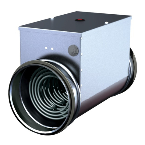
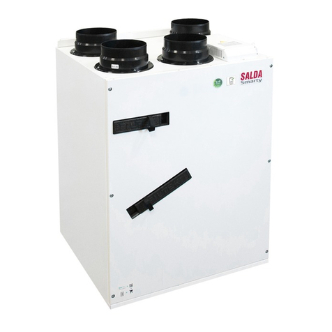
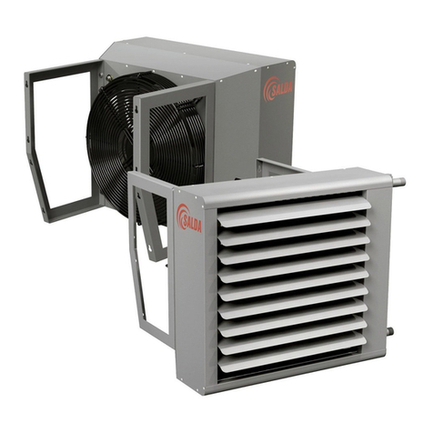
Salda SAV Guide

SAV
EN MOUNTING AND INSTALLATION INSTRUCTION 2
LT MONTAVIMO IR INSTALIAVIMO INSTRUKCIJA 26
DE MONTAGE- UND INSTALLATIONSANLEITUNG 74
RU ИНСТРУКЦИЯ ПО УСТАНОВКЕ И МОНТАЖУ 146
FR MANUEL DE MONTAGE ET D’INSTALLATION 26
IT MANUALE INSTALLAZIONE E MONTAGGIO 32

SAV v2019.062 | EN
SYMBOLS AND MARKING
Product name
Weight 00,00 kg
Made in Šiauliai, Lithuania
SKU000000
LN: gu634612
2019.01.01
1
4
5
2
6
3
AS THE HEAT EXCHANGER IS NOT ENTIRELY
DRAINABLE, MAKE SURE THAT IT IS FILLED WITH
A SUITABLE ANTIFREEZING MIXTURE IN CASE
OFFREEZING RISK.
Figure 1.1 - Technical label
1 - Logo; 2 - Product code (SKU); 3 - Product name; 4 - Technical data; 5 - Lot number and production date; 6 - Production place.
GENERAL INFORMATION
• Before installing the unit read the entire information provided in this document.
• Installation of the unit shall only be performed by trained and qualied personnel aware of installation of such type of units, inspection, mainte-
nance and tools required for installation works.
• While installing the unit, observe the international and national mechanical and electrotechnical safety requirements of the country in which the
product is intended to be installed and used.
• If the provided information is unclear or any doubts arise regarding safe installation and operation, please contact the manufacturer or repre-
sentative.
• The unit shall be operated only under the below listed conditions.
• It is strictly forbidden to use the unit for non-designed purposes or in contradiction to the specied working conditions without written permission
of manufacturer or representative.
• The manufacturer or representative shall be notied about any fault, including description of the fault and data specied on the product’s label.
• Any repair or dismantle of the unit in case of fault is forbidden without previous written permission of manufacturer or representative.
• Dismantling, repair or modication of the unit shall be performed only upon previous written consent from manufacturer or representative.
• The end user shall ensure that the unit is suitable for environmental conditions before ordering and installing the unit.
TRANSPORTATION AND STORAGE
All units are packed in the factory to withstand regular conditions of transportation.
Upon unpacking, check the unit for any damages caused during transportation. It is forbidden to install damaged units!!!
The package is only a protection means!
At unloading and storing the units, use suitable lifting equipment to avoid damages and injuries. Do not lift units by holding on power supply ca-
bles, connection boxes, air intake or discharge anges. Avoid hits and shock overloads. Before installation units shall be stored in a dry room with
the relative air humidity not exceeding 70% (at +20°C) and with the average ambient temperature ranging between 0°C and +30°C. The place of
storage shall be protected against dirt and water.
The storage is not recommended for a period longer than one year. In case of storage longer than one year, it is necessary to check free rotation
of bearings before installation (turn the impeller by hand).
DESCRIPTION
Casing is made of galvanized sheet and is coated with powder paint RAL 7040.
Water heater.
Ecient and silent fan.
Motor is controlled using voltage.
Grilles on the unit allows to change the direction of the supply air.
PURPOSE OF THE DEVICE
Unit is designed for room air heating and is designed to supply only clean air (free of chemical compounds causing metal corrosion, of substances
aggressive to zinc, plastic and rubber, of fats and of particles of solid, adhesive and bred materials).
OPERATING CONDITIONS
Unit is designed for indoor use only in temperature between 0°C and +40°C and relative humidity must not exceed 70%.
If operated in temperatures bellow 0°C, the antifrost protection of the water heater must be ensured.
Units are forbidden to be used in potentially explosive environment.
Unit is designed to supply only clean air (free of chemical compounds causing metal corrosion, of substances aggressive to zinc, plastic and rub-
ber, of fats and of particles of solid, adhesive and bred materials) to a room.
Maximum water temperature 100°C.
Maximum water pressure 1.6 Mpa.

SAV v2019.06 EN | 3
Water quality values must not exceed the following values:
- total amount of chlorine and sulphur ions must not exceed 150 mg/l (in case of copper pipes must not exceed 50 mg/l);
- the amount of oxygen must not exceed 0.1 mg/l;
- water acidity (pH) must be between 8.0 and 9.5;
- total hardness must not exceed 4.0 mval/l.
SAFETY PRECAUTIONS
Do not use this unit for purposes other than those provided in its design.
Do not dismantle and modify the unit. Such actions can cause mechanical fault or even injury.
Use special working clothes when installing and maintaining the unit. Be careful – angles and edges of the unit and its components can be sharp
and cause injuries.
Being near the unit, do not wear free streaming clothes that could be sucked into the operating fan.
Do not put ngers or any other objects into protection grilles of air intake and discharge. In case any foreign material gets into the unit, disconnect
the power supply source immediately. Before removal of foreign material, make sure that any mechanical movement in the unit has stopped. In
addition, make sure that the accidental switching-on of the unit is impossible.
Avoid direct contact with the ow of supplied and extracted air.
Do not connect the unit to the mains other than indicated in the product label on the casing of the unit.
Never use a damaged power supply cable.
Never touch with wet hands the power supply cables connected to the mains.
Never dip extension cords and plugs in water.
Do not install and use the unit on uneven surfaces or other unstable planes.
Never use this unit in the environment conducive to explosion and containing any aggressive materials.
MOUNTING
MECHANICAL CONNECTION
• Installation works shall be performed only by trained and qualied personnel.
• Unit shall be installed rmly and tightly to ensure safe operation.
• Protection from contact with impeller of the operating fan shall be ensured.
• The unit is mounted to the walls or ceiling by using specially prepared and supplied holders (Pic. 1, b, c).
• IMPORTANT. The unit shall not be connected in such way that water connecting tubes are directed downwards or upwards.
• Vibrations can be transmitted through walls or ceiling. If possible, the walls or ceiling shall be additionally insulated in order to suppress the noise.
• During installation, enough space must be retained for water connection and installation of water control components.
• If there is a possibility for condensate or water to access the fan motor, external protective measures shall be tted.
• When connecting the water heater, the weight of water pipes and heat tensions must not be transferred on the heater branches.
• When mounting threaded connections of supply pipes and heaters, two spanners must be used (Pic. 2).
• Pipes are connected to the heater in such way that they could be easily disassembled and the heater could be removed from the unit casing when performing
service or repair works.
• Pipes must be connected to the heater as shown on the casing of the unit (Pic. 3)
S1:
S2:
Water in
Water out
Inlet air ow
Water in
Water out
Inlet air ow

SAV v2019.064 | EN
S3:
bcd
ae
ELECTRIC INSTALLATION
Units contain rotating parts and are connected to the mains. It may cause risk to people health and life. Therefore, it is necessary to follow safety
requirements when performing installation works. In case of any doubts regarding safe installation and operation of the unit, please contact the
manufacturer or representative.
Installation works shall be performed only by trained and qualied personnel.
Make sure that specications of the connected mains correspond to the specications indicated in the product label on casing of the unit.
Selected power supply cable must correspond to the power of the unit.
IMPORTANT. When revolutions are adjusted by decreasing the voltage, the motor current can exceed the rated current under the low motor
voltages.
The fan must be connected according the designed electric connection scheme as in this document (Scheme 1) and as shown under the electric
connection box cover.
External protection device (automatic switch or fuse) must be connected. The operative current is selected 1.5 times greater than the maximum
current of the unit (indicated on the product label).
Grounding must be ensured for the unit.
Connect the TK contact group to the external thermal protection device of the motor.
If fan motor speed controller is used, ensure that it provides safe operation of the motor.
Frequency converters are not used for speed control of these devices.
#1
U1U2C GR
blue black brown yellow-green
#2
U1U2V1V2W1W2TK
brown black white red green blue yellow
MAINTENANCE
Maintenance of the unit shall be performed only by trained and qualied personnel.
The maintenance works for the unit shall be performed at least 2 times in a year.
Before maintenance works ENSURE THAT the unit is disconnected from the supply voltage, disconnect the water supply to the heater and wait
until the fan rotation stops and the heater cools down.
When carrying the maintenance works, follow the above work safety rules.
The following works must be carried in addition to general technical and cleanness maintenance:
FAN
Fan must be inspected and cleaned at least 2 times in a year.
High-eciency bearings are used in the motor. They do not have to be lubricated during the entire operational period of the motor.
Disconnect the fan from the power supply cable and dismount the fan (Pic. 5).
Carefully inspect the fan impeller for accumulated dust and other materials which could aect the balance of impeller. The misbalanced impeller
can cause vibration and premature wear of motor bearings.
Clean the impeller and the interior of casing using mild, non-aggressive and non-corrosive detergent and water.
For cleaning the impeller do not use high-pressure devices, cleaners, sharp tools or aggressive solvents which could scratch or damage the

SAV v2019.06 EN | 5
impeller.
When cleaning the impeller, do not immerse the motor in a liquid.
Ensure that balancing weights of the impeller are in appropriate position.
Ensure that the casing does not block the impeller.
Allow the impeller to dry before mounting the fan.
Mount the fan back to the unit (Pic. 5).
If the fan can not be dismounted, it can be cleaned while mounted to the unit casing. Clean the interior of the impeller, external surfaces of the
blades and the motor.
If the fan does not switch on after the maintenance works, contact the manufacturer.
WATER HEATER
Water heater should be inspected and cleaned at least 2 times in a year.
Ensure that the unit is water-tight and has no signs of corrosion. In case of any faults, remove it. If the faults can not be corrected, contact the
manufacturer.
Accumulated deposits on the surface of water heater can be removed using vacuum cleaner.
SELECTION OF POWER SUPPLY CABLE AND PROTECTIVE DEVICE
SAV 2000 SAV 4000 SAV 6000 SAV 9000
Cross-section of the power supply cable [mm²] 3x0,5 3x0,5 4x0,5 + 2x0,5 4x0,5 + 2x0,5
Circuit breaker*
Poles
1 1 3 3
[A] 1,6 6,0 3,0 4,0
* automatic switch with characteristic C
START-UP
Start-up of the unit shall be performed only by trained and qualied personnel.
The unit is ready for work after the supply voltage, selected external accessories are connected and the water heater is connected to the water
heating system.
Before start-up, make sure that power supply circuit corresponds to the specications indicated in the label.
Before start-up, make sure that the unit is connected to the mains in accordance with the wiring diagram shown in this document and under the
cover of the fan connection box.
Before start-up of the unit, make sure that the above instructions for safety and installation are applied.
Before start-up of the unit, make sure that the water connection is hermetic.
Upon start-up of the unit, make sure that the motor rotates evenly, without vibration and outside noise.
Upon start-up of the unit, make sure that the air ow generated by the unit and fan rotation direction match the direction indicated on the casing.
The current used by the unit shall be tested for compliance with the range of maximum current indicated in this document.
DIMENSIONS

SAV v2019.066 | EN
A
[mm]
B
[mm]
C
[mm]
a
[mm]
b
[mm]
b1
[mm]
c
[mm]
c1
[mm]
c2
[mm]
g
[mm]
e
[mm]
ød
[mm]
m
[kg]
SAV 2000 533 502 565 44 440 31 265 53 38 170 401 26,5 21,0
SAV 4000 588 627 565 44 561 33 265 53 38 220 455 26,5 34,0
SAV 6000 738 777 783 44 711 33 283 53 38 280 596 26,5 45,0
SAV 9000 818 852 818 44 786 33 318 57 45 280 676 26,5 57,0
TECHNICAL DATA
SAV 2000 SAV 4000 SAV 6000 SAV 9000
Phase / Voltage [50 Hz / V] ~1 / 230 ~1 / 230 ~3 / 400 ~3 / 400
Power [kW] 0,173 0,484 0,54 0,992
Current [A] 0,8 2,32 1,1 1,9
Speed [min-1]1392 1410 1405 1415
Max. air temperature [°C] +60 +70 +70 +70
Capacitor [µF] 8,0 8,0 - -
Protection class IP-44 IP-54 IP-54 IP-54
Wiring diagram #1 #1 #2 #2
Speed controller MTY1,5 / TGRV1,5 MTY2,5 / TGRV4 TGRT2 TGRT2
IMPROPER OPERATION AND REPAIR
Fault removal works shall be performed only by trained and qualied personnel.
Before start of repair works, ENSURE THAT the unit is connected from the supply voltage and wait until the fan motor stops and the heater cools
down.
Follow the above safety requirements.
When the unit switches-o:
Check if voltage and current of the mains correspond to the requirements indicated in the product label.
Check for power availability to the unit.
Upon elimination of power supply faults, switch-on the unit again.
When the fan does not rotate:
When the fan motor has stopped because of overheating and the external protection is activated:
Allow the motor to cool down for 15–20 minutes.
Eliminate the cause for motor overheating.
Switch the fan again.
When the fan does not switch again:
Disconnect the supply voltage.
Wait unit any mechanical movement stops, the motor cools down and the connected capacitors discharge.
Ensure that the impeller is not blocked.
Inspect the capacitor (for single-phase fans – according the connection diagram). If faults repeat, change the capacitor.
Decreased air ow:
Check if the water heater is not dirty. Clean the heater as described in sections “Maintenance” and “Water heater”.
Cold supply air:
Check the air temperature which is set by the thermostat.
Check the tightness of the water heater.
Check if the supply water and control assemblies are in order and operational.
Increased noise and vibration:
Clean the fan as described in section “Fan maintenance”.
If the fault can not be removed, please contact the supplier.
ACCESSORIES
SAV Fan Heater TRoom thermostat
GR
Fan speed controller MTY Room digital thermostat
Fan transformer speed controller TGRV AM Mixing point
Fan transformer speed controller TGRT VV 3-way water valve
VP Thermic water valve actuator 2-way water valve

SAV v2019.06 EN | 7

SAV v2019.068 | EN
11. DECLARATION OF CONFIMITY
Manufacturer
SALDA, UAB
Ragainės g. 100
LT-78109 Šiauliai, Lithuania
Tel.: +370 41 540415
www.salda.lt
Hereby conrms that the following products:
SAV*
(where by „*“ indicates possible unit design size and modication)
Provided it was delivered and installed in the facility in accordance with the included installation instructions, comply
with all applicable requirements in the following directives:
Machinery Directive 2006/42/EC
Pressure Equipment Directive 2014/68/EU
The following harmonized standards are applied in applicable parts:
LST EN ISO 12100:2011 - Safety of machinery - General principles for design - Risk assessment and risk reduction.
LST EN 378-2:2008+A2:2012 - Refrigerating systems and heat pumps - Safety and environmental requirements - Part 2: Design, construction,
testing, marking and documentation.
Should any alterations be made in the products, this declaration will no longer apply.
Notied body: VšĮ Technikos priežiūros tarnyba, Naugarduko g. 41, LT – 03227 Vilnius, Lithuania, identication number 1399.
Quality: Salda UAB activities are in line with the international quality management system standard ISO 9001:2015.
Date 2019-02-01
Giedrius Taujenis
Director product development

SAV v2019.06 EN | 9
12. WARRANTY
1. All equipment manufactured in our factory is checked in operating conditions and tested befor delivery. Test protocol is supplied together with
the unit. The equipment is shipped in good working order and condition to the direct client. The unit is warrantied for the period of two years from
the invoice date.
2. If equipment is found to have been damaged during transportation, a claim should be made against carrier, as we assume no responsibility for
such damage.
3. This warranty does not apply:
3.1. when transportation, storage, installation and maintenance instructions of the unit are violated;
3.2. when the equipment is improperly maintained, mounted - inadequate maintenance;
3.3. when the equipment without our knowledge and permission has been upgraded or unskilled repairs were made;
3.4. when the unit was used not for its original purpose.
3.5. Company SALDA UAB is not responsible for potential loss of property or personal injury in cases where AHU is manufactured without a
control system and the control system will be installed by the client or third parties. The manufacturer’s warranty does not cover devices that
will be damaged by installing the control system.
4. This warranty does not apply at these malfunction cases:
4.1. mechanical damage;
4.2. damage caused by entering outside objects, materials, liquids;
4.3. damage caused by natural disaster, accident (voltage change in the electricity network, lightning, etc..).
5. The company assumes no liability for its products either directly or indirectly damage, if the damage is caused by failure to comply with instal-
lation and mounting regulations, deliberate or careless users or third-party behavior.
These conditions are readily discernable when the equipment is returned to our factory for inspection.
If the direct client determines that equipment is found to be faulty, or a breakdown occurred, he should inform the manufacturer within ve working
days and deliver the equipment to manufacturer. Delivery costs should be covered by customer.
Manufacturer reserves the right to change this technical passport any time without prior notice, if some typographic
errors or inaccurate information is found, as well as after improving the apps and/or the devices. Such changes will be
included in the new issues of the technical passport. All illustrations are just for information and thus may dier from the
original device.
12.1. LIMITED WARRANTY COUPON
Warranty term
24 months*
I received complete package and technical manual of the product ready for usage. I have read warranty terms and conditions and agree with them:
..........................................................................................................................................................................
Customer’s signature
*refer to WARRANTY CONDITIONS
Dear User, we appreciate your choice and do hereby guarantee that all ventilation equipment manufactured by our Company is inspected and
thoroughly tested. An operational and high-quality product is sold to the direct buyer and shipped from the territory of the factory. It is provided with
a 24-month warranty since invoice issue date.
Your opinion is important to us, thus we always look forward to hearing your comments, feedback, or suggestions regarding technical and opera-
tional characteristics of the Products.
In order to avoid any misunderstandings, please read the instructions for installation and operation of the product as well as other technical docu-
ments of the product carefully. The number of the Limited Warranty Coupon and serial number of the product specied on the silver identication
sticker attached to the housing must match.
The Limited Warranty Coupon shall be valid provided that the seller’s stamps and records are clear. It is prohibited to change, delete, or rewrite
the data specied on it in any manner – such a coupon shall be invalid.
With this Limited Warranty Coupon the manufacturer conrms one’s obligations to implement the imperative requirements established by eective
laws on protection of consumer rights in the event of identication of any defects of the products.
The manufacturer reserves the right to refuse provision of free warranty servicing in cases when the warranty conditions listed below are disre-
garded.

10 | LT SAV v2019.06
SIMBOLIAI IR ŽYMĖJIMAI
Product name
Weight 00,00 kg
Made in Šiauliai, Lithuania
SKU000000
LN: gu634612
2019.01.01
1
4
5
2
6
3
AS THE HEAT EXCHANGER IS NOT ENTIRELY
DRAINABLE, MAKE SURE THAT IT IS FILLED WITH
A SUITABLE ANTIFREEZING MIXTURE IN CASE
OFFREEZING RISK.
Pav. 1.1 - Techninislipdukas
1 - Logotipas; 2 - produkto kodas (SKU); 3 - produkto pavadinimas; 4 - techniniai duomenys; 5 - gamybos užsakymo numeris ir pagaminimo
data; 6 - produkto pagaminimo vieta.
BENDRA INFORMACIJA
• Prieš montuojant įrenginį būtina perskaityti visą šiame dokumente pateiktą medžiagą.
• Įrenginio montavimą gali atlikti tik apmokytas ir kvalikuotas personalas, susipažinęs su tokio tipo įrenginių montavimu, jų patikra, aptarnavimu
ir reikalingais darbo įrankiais, montavimo darbams atlikti.
• Montuojant gaminį būtina laikytis tarptautinių ir valstybės, kurioje bus montuojamas ir naudojamas gaminys, mechaninių ir elektrotechninių
saugos reikalavimų.
• Jei pateikta medžiaga yra neaiški, ar kyla abejonių dėl saugaus montavimo ir naudojimo, kreipkitės į gamintoją ar jo atsovą.
• Įrenginys gali dirbti tik žemiau išvardintose sąlygose.
• Griežtai draudžiama naudoti įrenginį ne pagal paskirtį ar ne pagal numatytas darbo sąlygas, negavus tam raštiško gamintojo arba atstovo lei-
dimo.
• Atsiradus gedimui, būtina pranešti gamintojui ar jo atstovui, apibūdinti gedimą bei pateikti duomenis, nurodytus gaminio lipduke.
• Atsiradus gedimams, draudžiama remontuoti, ardyti įrenginį, prieš tai negavus gamintojo ar jo atstovo raštiško leidimo.
• Įrenginio ardymą, remonto darbus ar modikavimą galima atlikti tik gavus raštišką gamintojo arba jo atstovo sutikimą.
• Tiesioginis pirkėjas, prieš užsakydamas ir sumontuodamas įrenginį, turi įsitikinti, ar įrenginys yra tinkamas pasirinktoms aplinkos sąlygoms.
GABENIMAS IR SAUGOJIMAS
• Visi įrenginiai yra supakuoti gamykloje taip, kad atlaikytų normalias pervežimo sąlygas.
• Išpakavus įrenginį patikrinkite, ar transportuojant jis nebuvo pažeistas. Pažeistus įrenginius montuoti draužiama!!!
• Pakuotė yra tik apsaugos priemonė!
• Iškraudami ir sandėliuodami įrenginius, naudokite tinkamą kėlimo įrangą, kad išvengtumėte nuostolių ir sužeidimų. Nekelkite įrenginių už maitini-
mo laidų, pajungimo dėžučių, oro paėmimo arba šalinimo anšų. Venkite sutrenkimų ir smūginių perkrovų. Iki sumontavimo įrenginius sandėliuo-
kite sausoje patalpoje, kur santykinė oro drėgmė neviršyja 70% (esant +20°C), vidutinė aplinkos temperatūra - tarp 0°C ir +30°C. Sandėliavimo
vieta turi būti apsaugota nuo purvo ir vandens.
• Nepatariame sandėliuoti ilgiau, nei vienerius metus. Sandėliuojant ilgiau, nei vienerius metus, prieš montuojant būtina patikrinti, ar lengvai sukasi
guoliai (pasukti sparnuotę ranka).
APRAŠYMAS
Korpusas pagamintas iš cinkuotos skardos ir padengtas milteliniais dažais RAL 7040.
Vandeninis šildytuvas.
Našus ir tyliai veikiantis ventiliatorius.
Įtampa valdomas variklis.
Įrenginyje sumontuotos grotelės leidžia keisti pučiamo oro kryptį.
ĮRENGINIO PASKIRTIS
Įrenginys naudojamas oro šildymui patalpose ir skirtas pūsti tik švarų orą (be metalų koroziją skatinančių cheminių junginių; be cinkui, plastmasei,
gumai agresyvių medžiagų; be riebalų, kietų, lipnių bei pluoštinių medžiagų dalelių).
DARBO SĄLYGOS
• Įrenginys skirtas eksplotuoti tik uždarose patalpose temperatūroje nuo 0 ºC iki +40 °C ir santykinei drėgmei ne didesnei kaip 70%.
• Eksplotuojant žemesnėje kaip 0 ºC temperatūroje, būtina užtikrinant vandeninio šildytuvo apsaugą nuo užšalimo.
• Įrenginius draudžiama naudoti potencialiai sprogimui pavojingoje aplinkoje.
• Įrenginys pagamintas pūsti į patalpą tik švarų orą (be metalų koroziją skatinančių cheminių junginių; be cinkui, plastmasei, gumai agresyvių
medžiagų; be riebalų, kietų, lipnių bei pluoštinių medžiagų dalelių).
• Maksimali vandens temperatūra 100°C.
• Maksimalus vandens slėgis 1,6 MPa .

LT | 11SAV v2019.06
• Vandens kokybės rodikliai turi būti ne didesni, negu nurodyti:
- chloro ir sieros jonų bendrasis kiekis – ne daugiau 150 mg/l (jeigu vamzdžiai variniai – ne daugiau 50 mg/l);
- deguonies ne daugiau 0,1 mg/l;
- vandens rūgštingumas (pH) turi išlikti 8,0-9,5;
- bendrasis kietumas ne daugiau 4,0 mval/l.
APSAUGOS PRIEMONĖS
• Nenaudokite šio įrenginio kitiems tikslams, nei numatyta jo paskirtyje.
• Neardykite ir niekaip nemodikuokite įrenginio. Tai gali sukelti mechaninį gedimą ar net sužeidimą.
• Montuodami ir aptarnaudami įrenginį naudokite specialią darbinę aprangą. Būkite atsargūs - įrenginio ir jį sudarančiųjų dalių kampai ir briaunos
gali būti aštrios ir žeidžiančios.
• Šalia įrenginio nedėvėkite plevėsuojančių drabužių, kuriuos galėtų įtraukti į dirbantį ventiliatorių.
• Nekiškite pirštų ar kitų daiktų į oro paėmimo ir išmetimo apsaugines groteles. Bet kokiam svetimkūniui patektus į įrenginį, tuoj pat atjunkite nuo
elektros maitinimo šaltinio. Prieš pašalindami svetimkūnį įsitikinkite, kad sustojo bet koks mechaninis judėjimas įrenginyje. Taip pat įsitikinkite,
kad atsitiktinis įrenginio įjungimas - neįmanomas.
• Venkite tiesioginio sąlyčio su įrenginio įsiurbiamo ir išmetamo oro srove.
• Nepajunkite įrenginio prie kitokio elektros tinklo, nei nurodyta gaminio lipduke ant įrenginio korpuso.
• Niekada nenaudokite pažeisto maitinimo laido.
• Niekada į šlapias rankas neimkite į elektros tinklą pajungtų maitinimo laidų.
• Niekada nenardinkite prailginimo laidus ir kištukines jungtis į vandenį.
• Nemontuokite ir nenaudokite įrenginio ant nelygių paviršių ir kitokių nestabilių plokštumų.
• Niekada nenaudokite šio įrenginio sprogimui palankioje ir agresyvių medžiagų turinčioje aplinkoje.
MONTAVIMAS
MECHANINIS PAJUNGIMAS
Montavimo darbus gali atlikti tik apmokyti ir kvalikuoti darbuotojai.
Įrenginys turi būti sumontuotas tvirtai ir standžiai, tai užtikrins jo saugų naudojimą.
Būtina užtikrinti apsaugą nuo sąlyčio su dirbančio ventiliatoriaus sparnuote.
Įrenginys montuojamas prie sienų ar lubų panaudojant tam tikslui paruoštus ir tiekiamus laikiklius (pav. 1, b, c).
SVARBU. Įrenginį negalima jungti taip, kad vandens pajungimo vamzdeliai būtų nukreipti į viršų arba į apačią.
Vibracijos gali būti perduodamos per sienas ar lubas. Jei yra tokia galimybė, būtina papildomai izoliuoti sienas ar lubas, kad nuslopinti keliamą
triukšmą.
Montuojant įrenginį reikia palikti vietos vandeniui pajungti bei vandens reguliavimo komponentams sumontuoti.
Jei yra galimybė kondensatui ar vandeniui patekti ant ventiliatoriaus variklio, būtina sumontuoti išorines apsaugos priemones.
Jungiant vandeninį šildytuvą, vandens vamzdyno masė ir šiluminiai įtempimai neturi būti perkeliami ant šildytuvo atvamzdžių.
Montuojant įsriegtus tiekimo vamzdynų ir šildytuvų sujungimus, reikia naudoti du veržliarakčius (pav. 2).
Vamzdynai prie šildytuvo jungiami taip, kad atliekant aptarnavimo ir remonto darbus, vamzdynus būtų galima greitai išmontuoti ir išimti šildytuvą
iš įrenginio korpuso.
Būtina pajungti vamzdyną prie šildytuvo, kaip nurodyta ant įrenginio korpuso (pav. 3).
S1:

12 | LT SAV v2019.06
S2:
Water in
Water out
Inlet air ow
Water in
Water out
Inlet air ow
S3:
bcd
ae
ELEKTRINIS PAJUNGIMAS
Įrenginiai turi besisukančias dalis bei yra jungiami į elektros maitinimo tinklą. Tai gali sukelti pavojų žmogaus sveikatai bei givybei. Todėl atliekant
montavimo darbus būtina laikytis saugumo reikalavimų. Kilus abejonėms dėl saugaus gaminio montavimo ir naudojimo, prašome kreiptis į ga-
mintoją ar jo atstovą.
Montavimo darbus gali atlikti tik apmokyti ir kvalikuoti darbuotojai.
Įsitikinkite, kad prijungiamo elektros tinklo duomenys atitinka duomenis gaminio lipduke ant įrenginio korpuso.
Parinktas maitinimo laidas turi atitikti įrenginio galingumą.
SVARBU. Kai apsisukimai reguliuojami mažinant įtampą, esant mažoms varikio įtampoms, variklio srovė gali viršyti nominalią.
Ventiliatorių būtina pajungti pagal jam nustatytą elektros pajungimo schemą, kuri nurodyta šiame dokumente (1 schema) ir kaip yra pavaizduota
po elektros pajungimo dėžutės dangteliu.
Būtina pajungti išorinį apsaugos įrenginį (automatinį jungiklį ar saugiklį), kurio suveikimo srovė parenkama 1,5 karto didesnė už įrenginio mak-
simalią srovę (nurodyta gaminio lipduke).
Įrenginiui turi būti užtikrintas įžeminimas.
Ventiliatorių TK kontaktų grupė turi būti prijungta prie išorinio variklio šiluminės apsaugos įrenginio.
Jei naudojamas ventiliatoriaus variklio greičio reguliatorius, būtina įsitikinti, kad jis užtikrina saugų variklio darbą.
Šių įrenginių greičio reguliavimui dažnio keitikliai nenaudojami.
#1
U1U2C GR
mėlynas juodas rudas geltonas-žalias
#2
U1U2V1V2W1W2TK
rudas juodas baltas raudonas žalias mėlynas geltonas
APTARNAVIMAS
• Įrenginio aptarnavimą gali atlikti tik apmokytas ir kvalikuotas personalas.
• Įrenginio aptarnavimas turi būti atliekamas mažiausiai 2 kartus per metus.
• Prieš pradedant aptarnavimą, BŪTINA įrenginį atjungti nuo maitinimo įtampos, atjungti vandens padavimą į šildytuvą ir palaukti, kol sustos suktis

LT | 13SAV v2019.06
ventiliatorius ir atvės šildytuvas.
• Vykdydami aptarnavimo darbus laikykitės auksčiau išvardintų darbo saugos taisyklių.
• Apart bendro įrenginio techninio stovio ir švaros priežiūros, turi būti atliekami šie darbai:
VENTILIATORIUS
Ventiliatorius turi būti apžiūrimas ir valomas mažiausiai 2 kartus per metus.
Variklio konstrukcijoje panaudoti aukšto našumo guoliai. Jie nereikalauja jokio tepimo per visą variklio tarnavimo laiką.
Atjunkite ventiliatorių nuo maitinimo laido ir išmontuokite ventiliatorių (pav. 5).
Būtina kruopščiai apžiūrėti ventiliatoriaus sparnuotę, ar nesusidarė dulkių ir kitokių medžiagų apnašos, galinčios išbalansuoti sparnuotę. Išbalan-
savimas sukelia vibraciją ir greitesnį variklio guolių susidėvėjimą.
Nuvalykite sparnuotę ir korpuso vidų švelniu, netirpdančiu bei korozijos neskatinančiu plovikliu ir vandeniu.
Valydami sparnuotę nenaudokite aukšto slėgio įrenginių, šveitiklių, aštrių įrankių arba agresyvių tirpiklių, galinčių įbrėžti ar pažeisti sparnuotę.
Valydami sparnuotę nepanardinkite variklį į skystį.
Įsitikinkite, ar sparnuotės balansiniai svarsčiai savo vietose.
Įsitikinkite, ar sparnuotė nekliūna už korpuso.
Prieš sumontuojant ventiliatorių leiskite sparnuotei nudžiūti.
Sumontuokite ventiliatorių atgal į įrenginį (pav. 5).
Nesant galimybei išmontuoti ventiliatorių, galima išvalyti ir pritvitrtintą prie įrenginio korpuso. Reikia nuvalyti sparnuotės vidinę ir išorinę mentelių
puses bei variklį.
Jei po aptarnavimo darbų ventiliatorius neįsijungia – kreipkitės į gamintoją.
VANDENINIS ŠILDYTUVAS
• Vandeninis šildytuvas turi būti apžiūrimas ir valomas mažiausiai 2 kartus per metus.
• Būtina patikrinti ar nepraleidžia vandens ir ar nėra susidariusi korozija. Nustačius pažeidimus pašalinti juos. Jei tai neįmanoma padaryti, kreip-
kitės į gamintoją.
• Susikaupusias apnašas ant vandeninio šildytuvo paviršiaus, galima išvalyti vakuminio siurblio pagalbą.
MATINIMO LAIDO IR APSAUGOS ĮRENGINIO PARINKIMAS
SAV 2000 SAV 4000 SAV 6000 SAV 9000
Maitinimo laido skerspjūvis [mm²] 3x0,5 3x0,5 4x0,5 + 2x0,5 4x0,5 + 2x0,5
Apsaugos įrenginys*
Poliai
1 1 3 3
[A] 1,6 6,0 3,0 4,0
* automatinis jungiklis su C charakteristika
PALEIDIMAS
Įrenginio paleidimą gali atlikti tik apmokytas ir kvalikuotas personalas.
Pajungus maitinimo įtampą, pasirinktus išorinius priedus ir prijungus vandeninį šildytuvą prie vandens šildymo sistemos, įrenginys yra paruoštas
darbui.
Prieš paleidžiant įrenginį, būtina įsitikinti, kad maitinimo grandinė atitinka lipduke nurodytus duomenis,
Prieš paleidžiant įrenginį, būtina įsitikinti, kad įrenginys prijungtas prie elektros šaltinio, vadovaujantis jungimo schema, pavaizduota šiame doku-
mente bei po ventiliatoriaus pajungimo dėžutės dangteliu.
Prieš paleidžiant įrenginį, būtina įsitikinti, kad pritaikyti auksčiau išvardinti saugumo ir montavimo nurodymai.
Prieš paleidžiant įrenginį būtina įsitikinti, kad vandens pajungimas yra sandarus.
Paleidus įrenginį būtina įsitikinti, kad variklis sukasi tolygiai, nevibruoja ir neskleidžia pašalinio triukšmo.
Paleidus įrenginį būtina įsitikinti, kad įrenginio sukuriamas oro srautas ir ventiliatoriaus sukimosi kryptis atitinka kryptį, nurodyta ant korpuso.
Būtina patikrinti, ar įrenginio naudojama srovė neviršyja maksimalios srovės, kuri nurodyta šiame dokumente.

14 | LT SAV v2019.06
IŠMATAVIMAI
A
[mm]
B
[mm]
C
[mm]
a
[mm]
b
[mm]
b1
[mm]
c
[mm]
c1
[mm]
c2
[mm]
g
[mm]
e
[mm]
ød
[mm]
m
[kg]
SAV 2000 533 502 565 44 440 31 265 53 38 170 401 26,5 21,0
SAV 4000 588 627 565 44 561 33 265 53 38 220 455 26,5 34,0
SAV 6000 738 777 783 44 711 33 283 53 38 280 596 26,5 45,0
SAV 9000 818 852 818 44 786 33 318 57 45 280 676 26,5 57,0
TECHNICAL DATA
SAV 2000 SAV 4000 SAV 6000 SAV 9000
Fazė / įtampa [50 Hz / V] ~1 / 230 ~1 / 230 ~3 / 400 ~3 / 400
Galia [kW] 0,173 0,484 0,54 0,992
Srovė [A] 0,8 2,32 1,1 1,9
Apsisukimai [min-1]1392 1410 1405 1415
Maks. oro temperatūra [°C] +60 +70 +70 +70
Kondensatorius [µF] 8,0 8,0 - -
Apsaugos klasė IP-44 IP-54 IP-54 IP-54
El. pajungimo schema #1 #1 #2 #2
Apsukų reguliatorius MTY1,5 / TGRV1,5 MTY2,5 / TGRV4 TGRT2 TGRT2
GEDIMAI IR JŲ ŠALINIMAS
• Gedimų šalinimo darbus gali atlikti tik apmokyti ir kvalikuoti darbuotojai.
• Prieš pradedant remonto darbus, BŪTINA įrenginį atjungti nuo maitinimo įtampos ir palaukti, kol sustos suktis ir atvės ventiliatoriaus variklis bei
šildytuvas.
• Būtina laikytis auksčiau išvardintų saugumo reikalavimų.
Išsijungus įrenginiui būtina:
• Patikrinti ar tinklo įtampa ir srovė atitinka reikalavimus, nurodytus gaminio lipduke.
• Patikrinti, ar elektros srovė pasiekia įrenginį.
• Pašalinus elektros srovės tiekimo problemas, pakartotinai įjungti įrenginį.
Jei nesisuka ventiliatorius
Jei ventiliatoriaus variklis sustojo dėl perkaitimo ir yra suveikusi išorinė apsauga, reikia:
• 15-20 min. leisti varikliui atvėsti.
• Pašalinti variklio perkaitimo priežastį.
• Pakartoti ventiliatoriaus jungimą.
• Jei variklis pakartotinai neįsijungia, būtina:
• Atjungti maitinimo įtampą
• Palaukti kol sustos bet koks mechaninis judėjimas, atvės variklis ir išsikraus pajungti kondensatoriai.
• Įsitikinti, kad sparnuotė neužblokuota.
• Patikrinti kondensatorių (vienfaziams ventiliatoriams – pagal jungimo schemą). Jei gedimai kartojasi, pakeiskite kondensatorių.
Sumažėjęs oro srautas
• Patikrinkite ar nėra užsiteršęs vandeninis šildytuvas. Išvalykite šildytuvą, kaip nurodyta punkte „aptarnavimas“, „vandeninis šildytuvas“.
Tiekiamas šaltas oras.
• Patikrinkite termostato nustatytą oro temperatūrą.
• Patikrinkite vandeninio šildytuvo sandarumą.
• Patikrinkite ar tvarkingi ir veikiantys tiekiamo vandens ir reguliavimo mazgai.
Padidėjo triukšmas ir vibracijos.
• Išvalykite ventiliatorių, kaip nurodyta aprašyme „ventiliatoriaus aptarnavimas“.

LT | 15SAV v2019.06
Jei tai nepadeda, būtina kreiptis į tiekėją.
PRIEDAI
SAV Vandeninis šildytuvas TKambarinis termostatas
GR
Ventiliatorius greičio reguliatorius MTY Kambarinis skaitmeninis termostatas
Transformatorinis ventiliatoriaus greičio reguliatorius TGRV AM Reguliavimo mazgas RMG
Transformatorinis ventiliatoriaus greičio reguliatorius TGRT VV Trieigis vandens vožtuvas
VP Šiluminė vandens sklendės pavara Dvieigis vandens vožtuvas

16 | LT SAV v2019.06
11. ATITIKTIES DEKLARACIJA
Gamintojas
SALDA, UAB
Ragainės g. 100
LT-78109 Šiauliai, Lietuva
Tel.: +370 41 540415
www.salda.lt
Prisiimdami atsakomybę deklaruojame, kad produktai:
SAV*
(kur „*“ nurodo galimą įrenginio montavimo tipą bei modikaciją)
susiję su šia deklaracija ir, jei jie yra montuojami ir eksploatuojami taip kaip nurodyta montavimo instrukcijoje, atitinka žemiau išvardintas Europos
Sąjungos direktyvas:
Mašinų direktyvą 2006/42/EB
Slėginės įrangos direktyvą 2014/68/ES
Produktams, atitinkamomis dalimis, taikomi žemiau nurodyti standartai:
LST EN ISO 12100:2011 - Mašinų sauga. Bendrieji projektavimo principai. Rizikos vertinimas ir jos mažinimas.
LST EN 378-2:2008+A2:2012 - Šaldymo sistemos ir šilumos siurbliai. Saugos ir aplinkosauginiai reikalavimai. 2 dalis. Projektavimas, gamyba,
bandymai, ženklinimas ir dokumentai.
Jei produktuose bus atlikti bet kokie pakeitimai, ši deklaracija nebegalios.
Notikuotoji įstaiga: VšĮ Technikos priežiūros tarnyba, Naugarduko g. 41, LT – 03227 Vilnius, Lithuania, identikavimo numeris 1399.
Kokybė: Salda UAB vykdoma veikla atitinka tarptautinį kokybės vadybos sistemos standartą ISO 9001:2015.
Data 2019-02-01
Giedrius Taujenis
Technikos direktorius

LT | 17SAV v2019.06
12. GARANTIJA
1. Tiesioginiam pirkėjui parduodamas ir iš įmonės teritorijos išgabenamas veikiantis, kokybiškas gaminys. Jam suteikiama 2 metų garantija nuo
sąskaitos-faktūros išrašymo datos.
2. Jei įranga sugadinama pervežant, pretenzijos turi būti pateiktos transporto įmonei. Mūsų gamykla šių nuostolių nekompensuoja.
3. Garantija netaikoma, kai:
3.1 pažeidžiama gaminio transportavimo, saugojimo, montavimo bei priežiūros instrukcija;
3.2 netaisyklingai eksploatuojama, sumontuojama įranga ‒ netinkama priežiūra;
3.3 įranga be mūsų žinios ir sutikimo buvo modernizuota arba nekvalifkuotai atliktas remontas;
3.4 įrenginys naudojamas ne pagal tiesioginę paskirtį.
4. Garantija netaikoma tokiais įrenginio gedimo atvejais:
4.1 esant mechaniniams pažeidimams;
4.2 esant pažeidimams, kuriuos sukėlė į gaminio vidų patekę pašaliniai daiktai, medžiagos, skysčiai;
4.3 kai gedimas atsiranda dėl stichinės nelaimės, avarijos (įtampos pasikeitimo elektros tinkle, žaibo ir pan.) ar nelaimingo atsitikimo
5. Įmonė neprisiima atsakomybės už savo gaminių tiesiogiai ar netiesiogiai padarytą žalą, jei jos priežastis – įrenginio naudojimo ir
montavimo taisyklių bei sąlygų nesilaikymas, tyčinis arba neatsargus naudotojų ar trečiųjų asmenų elgesys.
Išvardintos eksploatacijos klaidos ir įrenginio pažeidimai nesunkiai pastebimi, grąžinus gaminį į gamyklą ir atlikus pirminę apžiūrą. Jei
tiesioginis pirkėjas nustato, kad ventiliacijos įranga neveikia ar turi defektų, jis per 5 darbo dienas turi kreiptis į gamintoją, nurodydamas
priežastį, bei pristatyti įrangą į gamyklą savo lėšomis.
Gamintojas šį techninį pasą gali keisti bet kada ir be įspėjimo, jei jame randama tipografnių klaidų arba informacijos netik-
slumų, taip pat patobulinus programas ir (arba) prietaisus. Tokie pakeitimai bus įtraukti į naujus techninio paso leidimus.
Visos iliustracijos skirtos tik iliustruoti, todėl jose vaizduojamas prietaisas gali nevisiškai atitikti originalą
12.1. GAMINIO RAGANTINIS TALONAS
Garantinis laikotarpis
24 mėnesiai*
Gavau visą paruoštą naudoti gaminio paketą ir techninį vadovą. Perskaičiau garantijos sąlygas ir sutinku su jomis:
..........................................................................................................................................................................
Kliento parašas
*žr. GARANTIJOS SĄLYGOS
Gerbiamas Naudotojau, vertiname Jūsų pasirinkimą ir garantuojame, kad visa mūsų įmonėje pagaminta ventiliacijos įranga yra patikrinama bei
kruopščiai išbandoma. Tiesioginiam pirkėjui parduodamas ir iš gamyklos teritorijos išgabenamas veikiantis ir kokybiškas gaminys. Jam suteikiama
24 mėnesių garantija nuo sąskaitos-faktūros išrašymo datos.
Mums svarbi Jūsų nuomonė, todėl visada laukiame Jūsų pastabų, atsiliepimų ar pasiūlymų dėl Gaminių techninių ir eksploatacinių savybių.
Kad išvengtumėte nesusipratimų, prašome atidžiai susipažinti su gaminio montavimo ir eksploatavimo instrukcijomis bei kitais gaminio techniniais
dokumentais. Gaminio garantinio talono ir serijos numeris, nurodytas ant korpuso priklijuotame sidabrinės spalvos identikavimo lipduke, turi sutapti.
Garantinis talonas galioja esant aiškiems pardavėjo spaudams, įrašams. Jame nurodytus duomenis draudžiama bet kokiu būdu keisti, trinti ar
perrašyti - toks talonas negalioja.
Šiuo garantiniu talonu gamintojas patvirtina įsipareigojimus vykdyti galiojančiuose vartotojų teisių gynimo įstatymuose nustatytus imperatyvius
reikalavimus, nustačius gaminių trūkumus.
Gamintojas pasilieka teisę atsisakyti suteikti nemokamą garantinę priežiūrą, kai nesilaikoma toliau išvardintų garantijos sąlygų.

18 | DE SAV v2019.06
1. SYMBOLE UND MARKIERUNGEN
Product name
Weight 00,00 kg
Made in Šiauliai, Lithuania
SKU000000
LN: gu634612
2019.01.01
1
4
5
2
6
3
AS THE HEAT EXCHANGER IS NOT ENTIRELY
DRAINABLE, MAKE SURE THAT IT IS FILLED WITH
A SUITABLE ANTIFREEZING MIXTURE IN CASE
OFFREEZING RISK.
Abb. 1.1 - Typenschild
1 - Logo; 2 - Interner Code ( SKU); 3 - Produktbezeichnung; 4 - Technische Daten; 5 - Produktnummer und Datum; 6 - Produktionsort.
ALLGEMEINES
Vor der Montage des Gerätes sind sämtliche in diesem Dokument enthaltenen Materialien durchzulesen.
Die Montage des Gerätes darf nur von geschultem und qualiziertem Personal durchgeführt werden, das mit der Montage, Kontrolle, Wartung
sowie entsprechendem Montagewerkzeug vertraut ist.
Bei der Montage des Produktes sind die internationalen sowie örtlichen Vorschriften des Betreiberlandes zur mechanischen und elektrotech-
nischen Sicherheit einzuhalten.
Sind die gelieferten Materialien unklar bzw. bestehen Zweifel hinsichtlich einer sicheren Montage und Bedienung, wenden Sie sich bitte an den
Hersteller bzw. seinen Vertreter.
Das Gerät ist nur unter folgenden Bedingungen zu betreiben.
Es ist streng verboten, das Gerät nicht bestimmungsgemäß oder nicht unter vorgeschriebenen Betriebsbedingungen einzusetzen, wenn keine
schriftliche Genehmigung des Herstellers bzw. Vertreters dafür vorliegt.
Im Störfall ist der Hersteller bzw. sein Vertreter zu benachrichtigen, unter Angabe der Störungsbezeichnung sowie der Daten aus dem Produk-
taufkleber.
Es ist untersagt, bei Störungen das Gerät ohne vorherige schriftliche Genehmigung des Herstellers bzw. seines Vertreters zu reparieren oder zu
zerlegen.
Abbauten, Reparaturen und Veränderungen am Gerät dürften nur mit schriftlicher Genehmigung des Herstellers bzw. seines Vertreters durchge-
führt werden.
Vor der Bestellung und Montage des Gerätes muss sich der Endkunde vergewissern, dass das Gerät den gewählten Umgebungsbedingungen
entspricht.
TRANSPORT UND LAGERUNG
Alle Geräte sind werksseitig so verpackt, dass sie den normalen Transportbedingungen standhalten können.
Nach Auspacken des Gerätes überprüfen Sie, ob es beim Transport nicht beschädigt wurde. Beschädigte Geräte dürfen nicht montiert werden!!!
Die Verpackung ist nur eine Schutzmaßnahme!
Beim Ausladen und Lagern der Geräte verwenden Sie geeignete Hebezeuge, um Schäden und Verletzungen zu vermeiden. Heben Sie die Geräte
nicht an Netzkabeln, Anschlusskästen, Zu- und Abluftstutzen. Vermeiden Sie Stöße und Schläge. Vor der Montage lagern Sie die Geräte in einem
trockenen Raum, wo die relative Luftfeuchte höchstens 70% (bei +20°C) beträgt und die durchschnittliche Umgebungstemperatur zwischen 0°C
und +30°C liegt. Der Lagerort muss vor Schmutz und Wasser geschützt sein.
Eine Lagerung länger als ein Jahr ist nicht empfehlenswert. Bei einer Lagerung länger als ein Jahr sind die Lager vor der Montage auf Freigän-
gigkeit zu prüfen (Flügelrad von Hand drehen).
BESCHREIBUNG
Das Gehäuse ist aus verzinktem Blech gefertigt und hat die Pulverbeschichtung RAL 7040.
Wasserheizregister.
Leistungsstarker und geräuscharmer Ventilator.
Spannungsgesteuerter Motor.
Im Gerät montiertes Gitter ermöglicht es, die Zuluftrichtung zu ändern.
VERWENDUNGSZWECK DES GERÄTES
Das Gerät wird zur Luftheizung in den Räumen verwendet und dient zur Lieferung von ausschließlich sauberer Luft (ohne chemische Verbind-
ungen, die Metallkorrosion hervorrufen; ohne aggressive Substanzen, die Zink, Kunststo und Gummi angreifen; ohne Partikeln von festen,
klebenden sowie faserigen Materialien).
BETRIEBSBEDINGUNGEN
Das Gerät ist für den Betrieb ausschließlich in geschlossenen Räumen bei Temperaturen zwischen 0 ºC und +40 °C und relativer Feuchte von
höchstens 70% bestimmt.

DE | 19SAV v2019.06
Beim Betrieb unter 0 ºC ist der Frostschutz des Wasserheizregisters sicherzustellen.
Die Geräte dürfen nicht in einer explosionsgefährdeten Atmosphäre betrieben werden.
Das Gerät ist zur Lieferung von ausschließlich sauberer Luft konstruiert (ohne chemische Verbindungen, die Metallkorrosion hervorrufen; ohne
aggressive Substanzen, die Zink, Kunststo und Gummi angreifen; ohne Partikeln von festen, klebenden sowie faserigen Materialien).
Maximale Wassertemperatur 100°C.
Maximaler Wasserdruck 1,6 MPa .
Wasserqualitätswerte sollen die angegebenen Werte nicht überschreiten:
- Gesamtgehalt an Chlor- und Schwefelionen – höchstens 150 mg/l (bei Kupferrohren – höchstens 50 mg/l);
- Sauerstogehalt höchstens 0,1 mg/l;
- Säuregehalt des Wassers (pH) soll zwischen 8,0 und 9,5 bleiben;
- Gesamthärte höchstens 4,0 mval/l.
SCHUTZMASSNAHMEN
Setzen Sie das Gerät ausschließlich bestimmungsgemäß ein.
Unternehmen Sie keine Umbauten und Veränderungen am Gerät. Dies kann zu mechanischen Beschädigungen und Verletzungen führen.
Bei Montage und Wartung des Gerätes tragen Sie spezielle Arbeitskleidung. Seien Sie vorsichtig – die Ecken und Kanten des Gerätes und seiner
Bauteile können scharf sein und Verletzungen zufügen.
Tragen Sie am Gerät keine weite Kleidung, die in den funktionierenden Ventilator eingezogen werden kann.
Greifen Sie nicht und stecken Sie keine Gegenstände in die Schutzgitter für Zu- und Abluft. Sollte ein beliebiger Fremdkörper in das Gerät geraten,
ist dieses sofort vom Netz zu trennen. Vor dem Entfernen des Fremdkörpers ist sicherzustellen, dass jegliche mechanische Bewegung im Gerät
zum Stillstand gekommen ist. Außerdem ist sicherzustellen, dass ein ungewolltes Wiedereinschalten des Gerätes nicht möglich ist.
Vermeiden Sie einen direkten Kontakt zur Zu- und Abluftströmung des Gerätes.
Schließen Sie das Gerät an kein anderes Stromnetz an, als im Produktaufkleber auf dem Gerätegehäuse angegeben.
Verwenden Sie niemals ein beschädigtes Netzkabel.
Nehmen Sie niemals ein am Netz angeschlossenes Kabel in nasse Hände.
Tauchen Sie Verlängerungskabel oder Steckverbindungen niemals ins Wasser.
Montieren und betreiben Sie das Gerät niemals auf unebenen oder sonstigen instabilen Oberächen.
Setzen Sie das Gerät niemals in einer explosionsgefährdeten oder aggressive Materialien enthaltenden Atmosphäre ein.
MONTAGE
MECHANISCHER ANSCHLUSS
Die Montagearbeiten dürfen nur von geschultem und qualiziertem Personal ausgeführt werden.
Das Gerät ist fest und starr zu montieren, damit ein sicherer Betrieb gewährleistet ist.
Es muss der Schutz vor dem Kontakt mit dem betriebenen Flügelrad des Ventilators gewährleistet sein.
Das Gerät wird an den Wänden bzw. Decken unter Verwendung der dafür vorgesehenen und mitgelieferten Halterungen montiert (Abb. 1, b, c).
WICHTIG. Das Gerät darf nicht so angeschlossen werden, dass die Wasseranschlussröhrchen nach oben oder nach unten zeigen.
Die Übertragung der Schwingungen kann über Wände oder Decken erfolgen. Wenn diese Gefahr besteht, sollten Wände oder Decken zusätzlich
isoliert werden, damit der Lärm abgedämpft wird.
Bei der Gerätemontage ist ausreichend Platz für den Wasseranschluss sowie die Wasserregelungskomponenten zu belassen.
Besteht die Möglichkeit zum Eindringen von Kondensat bzw. Wasser in den Ventilatormotor, sind externe Schutzvorrichtungen anzubringen.
Beim Anschließen des Wasserheizregisters darf kein Gewicht und keine Wärmespannungen der Wasserleitungen auf die Stutzen des Heizregis-
ters übertragen werden.
Bei Montage von Verschraubungen der Rohrleitungen und Heizregister sind zwei Maulschlüssel zu verwenden (Abb. 2).
Die Rohrleitungen sind am Heizregister so anzuschließen, dass sie bei Wartungs- und Instandsetzungsarbeiten schnell demontiert werden kön-
nen, um das Heizregister aus dem Gerätegehäuse herauszunehmen.
Die Rohrleitungen sind am Heizregister so anzuschließen, wie am Gerätegehäuse dargestellt (Abb. 3).
S1:

20 | DE SAV v2019.06
S2:
Water in
Water out
Inlet air ow
Water in
Water out
Inlet air ow
S3:
bcd
ae
ELEKTRISCHER ANSCHLUSS
Die Geräte verfügen über rotierende Teile und werden an ein Stromnetz angeschlossen. Dadurch kann Gefahr für Leib und Leben entstehen.
Deshalb sind bei allen Montagearbeiten die Sicherheitshinweise einzuhalten. Im Zweifelsfall betreend eine sichere Montage und Bedienung
des Produkts wenden Sie sich bitte an den Hersteller bzw. seinen Vertreter. Die Montagearbeiten dürfen nur von geschultem und qualiziertem
Personal ausgeführt werden.
Stellen Sie sicher, dass alle Angaben des Stromnetzes den Angaben des Produktaufklebers auf dem Gehäuse entsprechen.
Das Netzkabel muss der Leistungskapazität des Gerätes entsprechen.
WICHTIG. Wird die Drehzahl über Spannungsverringerung geregelt, kann der Motorstrom bei niedrigen Motorspannungen den Nennstrom über-
steigen. Der Ventilator ist gemäß dem in diesem Dokument angegebenen, ihm zugeordneten Schaltplan anzuschließen, welcher auch unter dem
Deckel des Stromanschlusskastens dargestellt ist (s. Plan 1). Es ist eine externe Schutzvorrichtung (automatischer Schalter bzw. Sicherung)
anzuschließen. Ihr Ansprechstrom ist 1,5 mal größer als der maximale Strom des Gerätes zu wählen (s. Produktaufkleber). Stellen Sie eine Er-
dung für das Gerät sicher. Die TL-Kontaktgruppe der Ventilatoren ist an einen externen Wärmeschutz des Motors anzuschließen.
Wird ein Drehzahlregler des Ventilatormotors eingesetzt, ist sicherzustellen, dass er eine sichere Funktion des Motors gewährleistet.
Zur Drehzahlregelung von diesen Geräten werden keine Frequenzumrichter verwendet.
#1
U1U2C GR
blau schwarz braun gelb-grün
#2
U1U2V1V2W1W2TK
braun schwarz weiß rot grün blau gelb
BEDIENUNG
Die Wartung darf nur von geschultem und qualiziertem Personal vorgenommen werden.
Die Wartung des Gerätes sollte mindestens 2 mal jährlich erfolgen.
Vor Beginn der Wartung ist das Gerät UNBEDINGT von der Spannungsversorgung zu trennen, das Heizregister ist von der Wasserversorgung zu
trennen und es ist abzuwarten, bis der Ventilator zum Stillstand gekommen ist und sich das Heizregister abgekühlt hat.
Beim Ausführen der Wartungsarbeiten müssen die oben genannten Arbeitssicherheitsvorschriften eingehalten werden.
Table of contents
Languages:
Other Salda Heater manuals
Popular Heater manuals by other brands

Whirlpool
Whirlpool WCC installation instructions

Siemens
Siemens DE 1113415 Installation and operating instructions

Velleman
Velleman HOTSPOT FT93N user manual

Bionaire
Bionaire BH1551 Instruction leaflet

Commercial Electric Heat
Commercial Electric Heat ODH-9000 installation instructions

Stanley
Stanley ST-40-GFA-E instruction manual