SALSA Alternator Low Deck 135 User manual

24855 7/17 | 85-000256_INST_C
ALTERNATOR REAR RACK INSTRUCTIONS
1
For additional product and safety information go to salsacycles.com/safety
At Salsa, we believe that a sense of adventure makes life better.
The bicycle can be so much more than just a bike; it’s a path
to new places, new people, and amazing experiences.
Thank you for your purchase. We hope it makes a good riding
experience even better!
Salsa. Adventure by bike.
®
WARNING: CYCLING CAN BE DANGEROUS. BICYCLE
PRODUCTS SHOULD BE INSTALLED AND SERVICED BY
A PROFESSIONAL MECHANIC. NEVER MODIFY YOUR BICYCLE
OR ACCESSORIES. READ AND FOLLOW ALL PRODUCT
INSTRUCTIONS AND WARNINGS INCLUDING INFORMATION
ON THE MANUFACTURER’S WEBSITE. INSPECT YOUR BICYCLE
BEFORE EVERY RIDE. ALWAYS WEAR A HELMET.
WARNING: The Alternator Rear Rack is designed and intended
for use as a rear rack only. DO NOT USE AS A FRONT RACK.
Compatibility & Intended Use
The Salsa Alternator Rack is designed specifically for mounting
to Salsa frames equipped with Alternator and Alternator 2.0
dropouts. Alternator Racks are available in the four versions
shown below.
Check to make sure the rack version you are attempting to install
is the correct match for the frame and maximum tire fitment.
WARNING: Alternator racks are designed specifically to be
mounted only to frames equipped with Alternator dropouts.
DO NOT USE WITH OTHER BIKES. Mounting to other frames may
result in an over-expansion or over-compression of the rack
lowers to fit the width of the frame, which may compromise the
structural integrity of the rack, or possible contact between the
rack and the wheel/tire due to variations in the rack-mounting
boss locations. All versions of the Alternator rack have a load
capacity of 27 kg (59.4 lb). Do not exceed this load limit.
H
(HEIGHT)
L
(LENGTH)
D
(HOOK SPACING #1)
E
(HOOK SPACING #2)
L2 L1
C
(CLEARANCE HEIGHT)
SEE NOTE A
SEE NOTE A
W
(DECK WIDTH)
A±10
(MOUNT WIDTH)
SEE NOTE B
50
(DIN-STANDARD
LIGHT MOUNT)
B
(CLEARANCE WIDTH)
RACK MODEL HEIGHT WIDTH LENGTH L1 L2 A B C C E
LOAD
CAPACITY
FITS FRAMES
WITH REAR
SPACING FITS FRAMES WITH MAX TIRE SIZE
Alternator Low Deck 135/148 325 110 340 135 210 190 100 305 260 300 27 kg (60 lb) 135–148 O.L.D. 29 x 2.1" (700 x 51 mm) w/o fender
29 x 1.65" (700 x 42 mm) w/ fender
Alternator Plus 135/148 340 135 325 115 210 190 135 320 260 315 27 kg (60 lb) 135–148 O.L.D. 29 x 3.0" / 27.5 x 3.25"
Alternator 170/177 340 135 325 115 210 230 140 320 260 315 27 kg (60 lb) 170–177 O.L.D. 29 x 3.0" / 27.5 x 3.25" / 26 x 4.3"
Alternator 190/197 340 135 325 115 210 250 146 320 260 315 27 kg (60 lb) 190–197 O.L.D. 29 x 3.0" / 27.5 x 3.25" / 26 x 4.8"
All measurements in mm unless noted.
Note A: Proper installation requires at least 6 mm of clearance to be maintained between any rotating wheel component and all portions of the rack.
Note B: Mount width “A” may be adjusted up to 10 mm in either direction to fit frame. if required adjustment is more than 10, select next size rack.

24855 7/17 | 85-000256_INST_C
ALTERNATOR REAR RACK INSTRUCTIONS
2
For additional product and safety information go to salsacycles.com/safety
• Alternator racks are not designed for carrying anything
other than panniers or rack-specific bags
• Do not modify the Alternator rack. Doing so will void
the warranty
• Rear racks may change the steering, handling, and braking
forces of your bike, especially when loaded
• Be sure to test the handling in a safe area before riding
• Make sure your load is evenly balanced and secure before
every ride (i.e. no loose straps to get caught in the wheels)
• Position reflectors and lights so that they are not obstructed
when the rack is loaded
• Do not use any hardware not included in Alternator Rack
packaging. Existing frame hardware may not be rated for
rack use!
WARNING: Installing this Salsa rack requires in-depth
knowledge of bicycle mechanics and professional-grade tools.
If you do not have the proper tools or knowledge to perform this
installation, please take your bicycle to your local bicycle dealer.
Failure to appropriately install this rack may lead to component
failure, resulting in serious injury. We recommend that you have
this product installed, adjusted and maintained by a professional
bicycle mechanic.
Tools:
4 & 5 mm Hex Wrenches
10 mm Box-End Wrench
Torque Wrench
Hacksaw
File
Marker
Level (optional)
Salsa Rack-Lock Seat Clamp
(for frames without seatstay
braze-ons)
2
9
10
11
13 12
12
13
1
3
4
5
6
78
2F
2A
2B
2C
2D
2G
2H
2J
2K
2E
Item # Description Qty
1 Alternator Rack 1
2 Lower Mount Kit
(see detail) 2
3 16 mm M5 Swivel-
Mount Bolt 2
4 M7 Washer 2
5 M6 Lock Nut 2
6 Lock Washer 2
7 Swivel Mount 2
8 Swivel Bolt 2
9 Ø8 mm Rack Strut 2
10 Strut End-Cap 2
11 Ø8 mm Bent Rack
Strut 2
12 16 mm M5 Bolt 4
13 M5 Washer 4
2
9
10
11
13 12
12
13
1
3
4
5
6
78
2F
2A
2B
2C
2D
2G
2H
2J
2K
2E
Item # Description Qty
2A 32 mm M6 Bolt 1
2B 35 mm M6 Bolt 1
2C 40 mm M6 Bolt 1
2D 42 mm M6 Bolt 1
2E 48 mm M6 Bolt 1
Item # Description Qty
2F M6 Washer (stainless) 2
2G Ø12 x 12L Spacer 2
2H Ø12 x 5L Spacer 2
2J Ø12 x 1L Spacer 4
2K Ø10 x 10L Spacer 2 Figure B
Figure A
Lower Mount Kit (detail for item 2 in Fig. A)
Figure B
Figure A

24855 7/17 | 85-000256_INST_C
ALTERNATOR REAR RACK INSTRUCTIONS
3
For additional product and safety information go to salsacycles.com/safety
Installation
1. Select Lower Mount Hardware
Before the lower legs for the rack can be attached to the
frame, the correct length mounting bolts and spacers must
be selected from the lower mounting hardware kit (Fig. B).
Selection is based on the frame’s material. Bolt length and
spacer configuration is independent of the frame model, rear
spacing width, or the version of the Alternator rack being
installed. Locate the frame’s material in Table 1 or 2 and
select the lower mounting hardware as indicated in that row,
cross-referencing Figure B from page 2. Please note that if you
are installing an Alternator rack on a frame which is using
Boost-148 Reduction plates between the frame plates and
swing plates, the bolt length and spacer configuration is
different. Make your hardware selection based on the info
in the lower portion of the table labeled for “With Boost
Reduction Plates”. Once hardware is selected, set the
remaining unused lower mounting hardware aside to avoid
incorrect installation and for safe keeping should the rack
be moved to a different frame in the future.
2. Attach the lower legs.
Depending on your frame, the lower legs of the rack may
need to be spread or pinched up to 10 mm. This is normal.
If the rack must be spread or pinched more than this, it is
likely that the wrong rack was selected for your frame.
Stop installation and consult your local Salsa dealer
or Salsa customer service.
• Using a 5 mm hex wrench, remove the upper pivot bolt
from both the right and left Alternator dropouts of the
frame (Fig. 1). Store these bolts aside in a safe place to use
again, should you choose to use the frame without the
rack installed
Figure 1
Table 1 – Lower Mount Hardware Selection Chart
FRAME MATERIAL/STYLE NONDRIVESIDE DRIVESIDE
Bolt Under-head
Washer(s)
Standoff
Spacers
Bolt Under-head
Washer(s)
Standoff
Spacers
Steel w/ standard DS plate 2C 2F 2G 2A 2F 2G
Steel w/ split DS plate 2D 2F 2G + 2H 2B 2F 2G+2H
Aluminum 2D 2F 2G + 2J 2B 2F 2G+2J
Titanium 2D 2F 2G + 2H 2B 2F 2G+2H
Carbon w/ Alternator 2.0 2E 2F 2K 2C 2F 2K
Table 2 – Lower Mount Hardware Selection Chart for Frames w/ Boost Reduction Plates
FRAME MATERIAL/STYLE NONDRIVESIDE DRIVESIDE
Bolt Under-head
Washer(s)
Standoff
Spacers
Bolt Under-head
Washer(s)
Standoff
Spacers
Steel w/ standard DS plate 2D 2F 2G 2B 2F 2G
Steel w/ split DS plate 2E 2F+2J+2J+2J 2G+2H 2C 2F+2J 2G+2H
Aluminum 2E 2F+2J+2J 2G+2H 2C 2F 2G+2H
Titanium 2E 2F+2J+2J+2J 2G+2H 2C 2F+2J 2G+2H
Carbon Boost reduction plates not supported on Salsa carbon frames

24855 7/17 | 85-000256_INST_C
ALTERNATOR REAR RACK INSTRUCTIONS
4
For additional product and safety information go to salsacycles.com/safety
• Starting on the non-driveside, assemble the stainless
washer and additional spacers (if any) under the head
of the non-driveside bolt. Pass the bolt and washer/spacer
assembly through the lower mounting tab of the rack. Add
the stand-off spacer(s). Pass the exposed end of the bolt
through the frame plate and swing plate, and thread it into
the brake adapter bracket, but do not fully tighten (Fig. 2)
• Move to the driveside and repeat the process, this time
threading into the M6 lock nut (Fig. 3). Again, do not
fully tighten
• The final assembly is shown in Figure 4. Check to make
sure there is about a 1–3 mm gap between the rack
mounting tab and the dropout hood
3. Loosen the rack’s mounting struts using a 4 mm hex wrench
and 10 mm box-end wrench (Figs. 5 & 6). Position the rack
struts in line with the seatstay mounts, ensuring that the rack
is level (parallel to the ground).
NOTE: Some frames equipped with Alternator dropouts
do not have seatstay mounts (like El Mariachi, Timberjack,
Woodsmoke, or Mukluk). In these cases, a Salsa Rack-Lock
must be used to create an attachment point for the mounting
struts. Some XL and XS sized frames may require use of bent
rack mounting struts (Item 11 in Fig. A).
4. Mark how long the rack struts need to be to reach the seatstay
mounts (Fig. 7).
5. Cut the rack struts to length with a hacksaw, file away any
rough edges, and slide them back into the swivel mount.
Reinstall the end caps (Fig. 8). Check to ensure stay ends
do not extend past deck surface.
6. Attach the rack struts to the seatstays using the remaining two
16 mm M5 bolts and washers (Items 12 & 13 in Fig. A) (Fig. 9).
Figure 9
Figure 8
Figure 7
Figure 5 Figure 6
Figure 3
SECTION
A-A
Figure 4 DrivesideNon-Driveside
Gap
SECTION
A-A
Upper
Pivot
Bolt
Washer
Rack
Spacers
Swing Plate
Frame Plate
Disc
Mount
Figure 2

24855 7/17 | 85-000256_INST_C
ALTERNATOR REAR RACK INSTRUCTIONS
5
For additional product and safety information go to salsacycles.com/safety
SALSA CYCLES
6400 West 105th Street, Bloomington, MN 55438
Tel: 877-668-6223 Fax: 952-983-6210
www.salsacycles.com
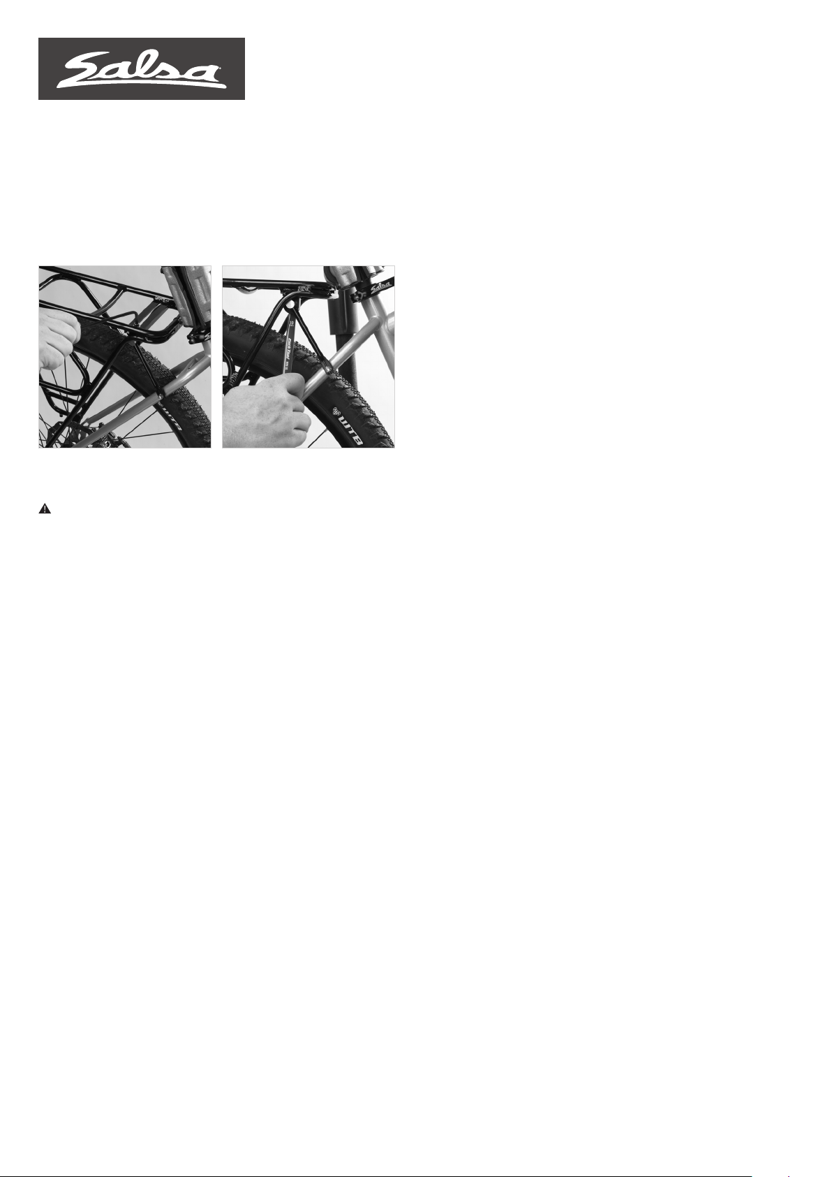
7. Secure the struts in the swivel mounts, again using the 4 mm
hex and 10 mm box-end wrenches (Figs. 10 & 11).
8. Tighten the upper pivot bolts of the Alternator dropouts to
8 Nm and tighten the seatstay strut mounting bolts to 2–3 Nm.
Ongoing Maintenance
WARNING: Improper installation of bolts may lead to product
failure, causing serious injury. Do not exceed specified torque
values. Periodically inspect bolts and retighten if required.
Frequently check to make sure that all of the rack hardware
is properly torqued per these instructions. Check to make sure
that the rack mounting bolts are properly tightened and secure
the rack to the bicycle frame. Periodically check for any signs
of cracking or failure and discontinue use if rack is damaged.
Warranty
Salsa Cycles warrants this new Salsa product against defects
in materials and workmanship for two (2) years from the original
date of retail purchase by the consumer. This limited warranty
is expressly limited to the repair or replacement of the original
product, at the option of Salsa Cycles, and is the sole remedy
of the warranty. This limited warranty applies only to the original
purchaser of the Salsa product and is not transferable. In no
event shall Salsa Cycles be liable for any loss, inconvenience
or damage, whether direct, incidental or consequential
or otherwise resulting from breach of any express or implied
warranty or condition, of merchantability, fitness for a particular
purpose, or otherwise with respect to this product except as set
forth herein.
This warranty does not cover the following:
• Damage due to improper assembly or follow-up maintenance
or lack of skill, competence or experience of the end user
• Products that have been modified, neglected, used in
competition or for commercial purposes, misused or abused,
involved in accidents or anything other than normal use
• Damage or deterioration to the surface finish, aesthetics
or appearance of the product
• Normal wear and tear
• Labor required to remove and/or refit and re-adjust the
product within the bicycle assembly
TO THE EXTENT NOT PROHIBITED BY LAW, THESE WARRANTIES
ARE EXCLUSIVE AND THERE ARE NO OTHER EXPRESS
OR IMPLIED WARRANTIES OR CONDITIONS INCLUDING
WARRANTIES OR CONDITIONS OF MERCHANTABILITY AND
FITNESS FOR A PARTICULAR PURPOSE.
Proof of purchase is required before a warranty claim is processed.
Salsa Cycles therefore strongly encourages warranty registration
at salsacycles.com. Failure to register will not affect consumer
rights under the limited warranty stated above, so long as the
consumer can show in a reasonable manner proof of original
ownership and the date the Salsa Cycles product was purchased.
If you have any questions contact warranty@salsacycles.com
Figure 11
Figure 10
This manual suits for next models
7
Table of contents
Other SALSA Bicycle Accessories manuals

SALSA
SALSA TIMBERJACK User manual

SALSA
SALSA EXP Series User manual

SALSA
SALSA EXP Series User manual

SALSA
SALSA EXP Rubber Straps User manual

SALSA
SALSA EXP SERIES User manual

SALSA
SALSA REGULATOR Ti SEATPOST User manual

SALSA
SALSA Guide Seatpost User manual

SALSA
SALSA 465 User manual

SALSA
SALSA Minimalist User manual