manuals.online logo
Brands
  1. Home
  2. •
  3. Brands
  4. •
  5. Salt Dogg
  6. •
  7. Spreader
  8. •
  9. Salt Dogg 4553 User manual

Salt Dogg 4553 User manual

9
TM
Instruction Manual
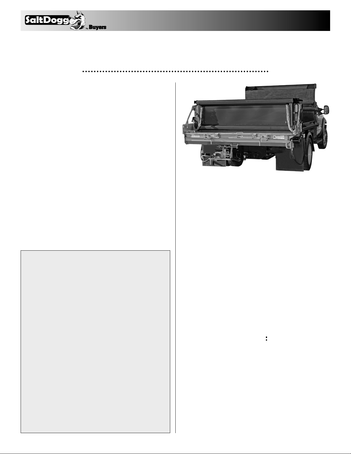
Direct Drive & 5:1 Gear Reduction
Under Tailgate Spreaders
UNDER TAILGATE SPREADER WARRANTY
This warranty replaces all previous warranties and no employee
of this company is authorized to extend any additional warran-
ties, or agreements, or implications not explicitly covered herein.
Buyers Products Company warrants all parts of the product to
be free from defects in material and workmanship for a period of
(1) one year from the date of original installation. Parts must be
properly installed and used under normal conditions. Normal wear
is excluded.
Any part which has been altered, including modification, misuse,
accident, or lack of maintenance will not be considered under this
warranty. Hydraulic units are not to be disassembled without
the express written permission from Buyers Products Company.
The sole responsibility of Buyers Products Company under this
warranty is limited to repairing or replacing any part(s) which
are returned, prepaid, 30 days after such defect is discovered,
and returned part(s) are found to be defective by Buyers Products
Company.
Authorization from Buyers Products Company must be obtained
before returning any part. The following information must accom-
pany defective parts returned to Buyers Products Company: RMA#,
spreader model, serial number, date installed, and distributor from
whom it was purchased. Buyers Products Company shall not be
liable for damage arising out of failure of any unit to operate prop-
erly, or failure, or delay in work, or for any consequential damages.
No charges for transportation or labor performed on any part will
be allowed under this warranty.
NOTE: This manual applies to spreaders starting
with Serial No. 4553
Table of Contents
Warranty Information ............................................... 1
Spreader Installation Instructions ........................ 1,2
Spreader Installation Drawing ................................. 2
Spinner Assembly Instructions..............................3,4
Spinner Assembly Drawing ...................................3,4
Hydraulics Installation ............................................. 5
Operating Instructions ...........................................5,6
Recommended Maintenance.................................... 6
Parts list: Spreader Assembly .................................. 7
Spreader Parts Drawing ........................................... 7
Parts List: Hardware Box ......................................... 8
Spinner Components Drawing ................................. 8
Auger Replacement Kit............................................. 8
Installation Instructions
NOTE: The left and right end plates may, on
occasion, get bent through improper handling
during shipment or storage. If this should hap-
pen, square and true the left and right end plates
before installation.
1. Aligning the spreader:
A. Position the spreader with the truck such that
the auger drive is located on the right side of the
truck (passenger side).
B. Lift the spreader up and under the dump body
tailgate, positioning the spreader forward as close
as possible to the dump body. The tailgate of the
dump body should lay down horizontally over the
spreader.
C. Support the spreader solidly and securely when
positioning for mounting.
2. Attach mounting brackets (See hardware
installation drawing on page 2.)
A. Attach a quick detach plate, (Item 1) to both
sides of the spreader frame using hinge pins (Item
2) and a hairpin cotter pins (Item 5).
B. Position the (2) quick detach plates over the
dump body rub rails and flush with rear edge of
dump body.
C. Weld the (2) quick detach plates to the dump
body rub rails. Weld the plates continuously around
(3) sides of each plate. Do not weld along the edge
of the plates next to the attachment pin.
—continued inside
9049 Tyler Blvd. • Mentor, Ohio 44060
Phone (440) 974-8888 • Fax (440) 974-0165
Toll-Free Fax 800-841-8003 • saltdogg.com
2
TM
D. Align the pin brace (Item 4) on the dump body
using the iron brace (Item 3) for exact positioning.
For proper fit, hanger iron brace may require some
minor bending.
E. Weld the (2) pin braces (Item 4) to the dump
body sides, all around.
F. Attach the iron braces (Item 3) to the pin braces
on the sides of the dump body and the sides of the
spreader using (2) hairpin cotter pins (Item 5).
G. If there is a gap between the spreader and the
dump body, weld or bolt a steel strip to the forward
edge of the spreader to cover the gap.
H. If you have purchased the tailgate side shields
(purchased separately as P/N 924F0106), bolt or
weld them to the inside of the tailgate to prevent
material spillage at the ends of the spreader.
1
2
3
4
5
DUMP BODY
SPREADER
FRAME
Mounting Hardware Installation Drawing
Bill of Materials
1 2 Quick Detach Plate 924F0102 3009526
2 2 Hinge Pin 924F0103 3011139
3 2 Hanger Iron Brace 924F0101 3011137
4 2 Pin Brace 9240021B 3000210
5 6 Hair Pin Cotter 5/32" HP12 HP12
item qty. description carbon stainless
3
TM
3. Spinner assembly installation: (See installation
drawings on pages 3 and 4.)
A. Attach the spinner shield (Item 2) to the spinner
frame (Item 1) using (3) 5/16-18 x 3/4 cap screws
and (3) 5/16-18 hex flange nuts.
B. Attach the spinner disk sub assembly (Item 3)
to the hydraulic motor on the spinner frame and
tighten the set screw in the disk collar.
Note: Be sure to lubricate the hydraulic motor shaft
generously with Never Seez lubricant before assem-
bling.
C. Attach the spinner frame assembly (Item 1) to
the lower tray of the spreader with the hinge rod
(Item 5) and attach (2) hairpin cotter pins.
D. Weld bar (Item 7) on the outside of the truck’s
(driver’s side) main frame rail. Locate the center of
the hole in the bar (Item 7) 11-1/2" vertically below
the dump body hinge pin center.
E. Bolt the spinner lug (Item 6) and hose clamp to
the spinner frame using (1) 5/16-18 x 3/4 hex head
cap screw and (1) 5/16-18 x 1-1/2 hex head cap
screw with (2) 5/16 -18 hex nuts.
F. Attach one parallel linkage rod (Item 4) to the
spinner lug (Item 6) using (1) 1/2" flat washer and
(1) hairpin cotter pin. Attach the other parallel
linkage rod (Item 4) to the frame bar (Item 7) using
another 1/2" flat washer and another (1) hairpin
cotter pin.
G. Keeping the spinner assembly level, remove
the set screw from the clamp collar and secure the
spinner frame in place using the spinner assembly
lock.
H. Weld the (2) parallel linkage rods (Item 4) solidly
together.
Truck Frame
Hinge Rod
Spinner
Frame
Spinner
Lug Bar
Spreader
Dump Body
Hinge
Bar
Spinner
Frame
Spreader
Hanger Iron
Brace
Parallel Linkage, Spinner Frame & Bar
Installation Drawings
4
TM
1
3
5
7
4
6
2
Weld this bar to
truck frame
Weld these
rods together
at final assembly.
Parallel Linkage, Spinner Frame & Bar
Installation Drawings (cont.) Bill of Materials
1 1 Spinner Frame Assy. 3001471 3006679
2 1 Spinner Shield 924F0015 3006659
3 1 Spinner disk Assy. 3001472 3001472
4 2 Linkage Rods, Welded 924F0012 924F0012
5 1 Hinge Rod 924F0018 3006646
6 1 Spinner Lug 924F0013 3006645
7 1 Bar 924F0014 924F0014
item qty. description carbon stainless
92420A & 92420SSA
Direct Drive Under Tailgate Spreaders
Using hose number 3008112, insert one end into
the bottom of the ball valve assembly. Insert the
other end into the LH port (when looking from rear)
of the hydraulic motor.
92430A & 92430SSA
5:1 Gearbox Under Tailgate Spreaders
Using hose number 3008113, insert one end into
the bottom of the ball valve assembly. Insert the
other end into the LH port (when looking from rear)
of the hydraulic motor.
Insert other end of
hose into port on
bottom of hydraulic
motor
Insert one
end of
hose Into
bottom of
ball valve
Attach inlet
flow here
3 0 0 8113
3 0 0 8112
Insert one
end of
hose into
bottom of
ball valve
Insert other end
of hose into the
port on hydraulic
motor
Attach inlet
flow here
5
TM
Hydraulic Installation Instructions
A. During assembly take precautions to keep all
hydraulic components as clean as possible.
B. Allow enough hose length to prevent kinking
and stretching of the hoses and to permit raising
the dump body. Support long hoses with wire ties
or clamps.
C. Protect hoses from wear caused by sliding and/
or vibration.
D. For proper rotation of auger and spinner motors,
hoses may be reversed.
Note: Use of a pipe joint sealant compatible with
hydraulic oil is recommended for all screw fittings.
E. Use swivel type hose ends to connect hoses to
flow valve. Damage to valve body may occur if the
fittings in flow valve are over tightened
F. To achieve a positive shutoff of the auger mo-
tor, the inlet flow must pass through the ball valve
(pre-mounted to the spreader) & the supplied hose
must connect the ball valve to the auger’s hydrau-
lic motor as shown in the figures on the bottom of
page 4. (Inspection of this hose is recommended to
ensure no damage has occurred during shipping)
Valve 1/2" Quick Disconnects
3/4" (1)
Wire Hose
3/4" (1) Wire Hose
1/2" (1) Wire Hose
1/2" (1) Wire Hose
1/2" (1) Wire Hose
Auger Motor
CW Rotation
Ball
Valve
Spinner Motor
CCW Rotation
3/4" Quick
Disconnects
3/4" (2) Wire Hose
1-1/4" Spiral
SuctionHose
3/4" (2) Wire Hose
1/2" (1) Wire Hose
Tank
Pump
3
14
Hose
5
T
A
P
S
Bill of Materials
1 HV715 1 Dual Flow Regulator Valve
2 HVC1 1 Dual Flow Regulator Console
3 SMR15 1 15 Gallon Reservoir
4 3008521/ 1 Ball Valve Assembly (Stainless/Carbon)
3008523
5 3008112/ 1 Hose (Direct Drive/5:1 Gearbox)
3 0 0 8113
item part no. qty. description
Hydraulic Pump Diagram
Operating Instructions
1. Pre-start up.
A. Use high grade non foaming hydraulic oil to fill
reservoir about 3/4 full.
B. Position valve on/off lever to off.
C. Move auger and spinner knobs on the valve to
the open position.
D. Engage PTO and circulate hydraulic oil for sev-
eral minutes to warm up.
E. Move valve on/off lever to on.
F. Inspect hydraulic system for leaks.
G. Check auger and spinner to see if they are work-
ing properly.
H. Refill reservoir to 3/4 full.
I. Hydraulic system should now be ready for use.
2. Initial use of spreader
A. Shut off spinner and auger knobs and position
the on/off lever to on. Engage the PTO and allow
the hydraulic system to warm up.
B. Open the cover plate and secure vertically with
locking brackets.
C. Open dump body tailgate as wide as possible
from bottom without bearing against cover plate.
Set stop chains.
D. Position spinner assembly to the far left (drivers
side), tighten clamp. Determine placement of mate-
rial at various spinner and auger speeds by spread-
ing a small amount of material (Far left position
used to spread (3) three or (4) four lane highway
from right lane).
E. Position spinner assembly to the far right (pas-
senger side), tighten clamp. Determine placement
of material at various spinner and auger speeds
by spreading a small amount of material (Far right
position used to spread (4) four lane highway from
left lane).
F. Changing auger and spinner speeds on the valve
and placing spinner at various positions from left to
right will produce various spread patterns.
CAUTION
A. Be sure everyone is standing clear.
B. Be alert for anything that may require shutting
down the system.
C. Before working in or around spreader equip-
ment, be sure all hydraulic controls are moved to
off position.
6
TM
3. Using the Auger Lock-out System
A. Shut off spinner and auger and position the
main hydraulics on/off lever to off.
B. Remove the lock-out pin, rotate the handle, and
insert the pin through the holes in the handle and
the bracket to prevent accidental engagement of
the hydraulics. (see illustration below)
C. The lower tray may now be opened for servicing
the auger.
D. After servicing, first close and lock the tray then
reverse the steps to move the handle and pin back
to their original positions. BE SURE TO REINSERT
THE LOCK-OUT PIN THROUGH THE HOLES IN
THE HANDLE AND THE BRACKET.
E. Turn the main hydraulics back on and the
spreader is ready for operation.
Recommended Maintenance
A. Warm up hydraulic system before using.
B. Keep the reservoir 3/4 full with high grade non-
foaming hydraulic oil.
C. Use precautions to keep contaminants from get-
ting in reservoir when filling.
D. Quick connects are a prime source of
contamination.
1. Clean quick connects before connecting or
disconnecting them.
2. Protect quick connects from contaminates at
all times.
E. Lubricate all bearings with suitable type grease
on a regular basis. More frequent lubrication is
recommended during periods of heavy use.
F. Lubricate the spinner hinge rod periodically.
G. Maintain the proper lubrication level in all gear-
boxes with SAE 90 gear lubricant.
H. When not in use, keep the spreader tray empty
to prevent freezing of material around auger in
extremely cold weather.
I. To extend the life of your spreader:
1. Hose down and clean after each use.
2. Repaint and/or oil after each season.
CAUTION
Position the valve on/off control lever in the off posi-
tion when the spreader is not in use or is removed. In
the event the valve on/off control lever is left in the on
position, a heat problem may occur as the pump contin-
ues to pump oil to the hydraulic valve. This could cause
a hose to burst spraying hot oil.
CAUTION
Before working in or around the auger area, the valve
control lever must be in the off position. Disengage PTO,
shut off engine, and follow the auger lock-out instruc-
tions. MAKE SURE THE LOCK-OUT PIN IS ALWAYS USED
IN BOTH THE ON AND OFF POSITIONS. After servicing
is complete, reverse the process to restore the spreader
function.
4. Miscellaneous
A. Valve setting changes may be made with truck
in motion.
B. By moving on/off lever to the off position, spin-
Auger ON
ner and auger may be stopped at the same time
without changing their valve settings.
C. Close cover plate flat over spreader trough and
lock in place for normal use of dump truck. Tailgate
may be opened from top or bottom.
D. When truck is used for extensive hauling the
spinner assembly should be removed.
E. If auger clogs, shut off spinner, open auger knob
valve and increase the engine speed. With the
engine at a higher speed, move the valve lever
from the on to the off positions rapidly; repeat as
needed. This action may unclog the auger. If this
action fails to free the auger, manual unclogging
will be required.
Auger OFF
7
TM
TM
1
24
14 21
2
310
11
12
16
20 19
17
13 14 15
9
13
15
4
18
5
35
27 33
32
36
38 39
37
22
23
26
34
6
78
31
30
13
25
13
25
20
13
28 29
31 30
13
14
20
Spreader Assembly Parts List
1 1 Spreader frame 3008421 3008436
2 1 Formed lower tray 3008429 3008443
3 1 Top cover 3006966 3006969
4 1 Auger 924F0081 924F0081
5 1 Adaptor 924F0084 924F0084
6 1 Spacer sleeve 9240083 9240083
7 1 Bolt FCS050013300 3001250
8 1 Nut, hex 92401213 3001253
9 1 Spinner cover plate 924F0105 3000270
10 1 Hairpin cotter pin 1420016 1420016
11 2 Cover latch bracket 3006965 3006968
12 2 Locking handle 9240063 3000268
13 11/12 Capscrew FCS038016100
FCS038016100SS
(direct drive/5:1 gearbox)
14 9 Nut, elastic stop FNE038016044
FNE038016044SS
15 8/4 Washer, flat FWF038100007
FWF038100007SS
16 1 Bearing 9240086 9240086
17 1 Felt gasket 9240087 9240087
18 2 Latch, cover mounting 3008430 3008447
19 2 Capscrew FCS038016125
FCS038016125SS
20 6/7 Nut, serrated flange 92 401211 3001255
(direct drive/5:1 gearbox)
Bill of Materials
item qty. description carbon stainless
21 2 Capscrew FCS038016350 3001249
22 2 Nut, elastic stop FNE063011069 3001247
23 1 Cam handle passenger side 3008433 3008444
24 1 Cam handle driver side 3008431 3008446
25 4 Washer, lock
FLW038069009
FLW038069009SS
26 1 Plate, motor mount 3000458 3001367
27 1 Plate, gearbox mount 3000457 3001366
28 5/4 Capscrew
FCS050013100
FCS050013100SS
(direct drive/5:1 gearbox)
29 4 Washer, lock
FWL050088013
FWL050088013SS
30 3 Nut, serrated flange 92401212 3001523
31 3/2 Carriage bolt FCB050013100 3001522
(direct drive/5:1 gearbox)
32 1 Gearbox 9240089 9240089
33 1 Hydraulic motor CM034P CM034P
34 1 Hydraulic motor CM074P CM074P
35 1 Hose, direct drive 3 0 0 8112 3 0 0 8112
36 1 Hose, 5:1 gearbox 3 0 0 8113 3 0 0 8113
37 1 Ball valve assembly 3008523 3008521
38 2 Capscrew 3008549 3008549
39 2 Washer, Lock
FWL025050006SS
FWL025050006SS
item qty. description carbon stainless
8
TM
1
2
3
6
7
4
5
8
9
3011293 Rev. A
Bill of Materials
1 924F0081 1 Auger
2 9240083 1 Adaptor Sleeve
3 924F0084 1 Adaptor Shaft
4 9240086 1 Bearing
5 9240087 1 Felt Gasket
6 FCS050013300 1 Capscrew
7 92401213 1 Locknut, Reversible Hex
8 FCS038016125 2 Capscrew
9 92 401211 2 Nut, Serratted Flange
item part no. qty. description
1
2
5
6
7
9
11
4
8
10
3
1
2
3
4
5 6
7
9
10
11
12
13
15
8
14
Hardware Box Parts List Hardware Bag Contents
Auger Replacement Kit (924F0081AK)
Bill of Materials
1 1 Spinner Frame Assy. 3001471 3006679
2 1 Spinner Shield 924F0015 3006659
3 1 Spinner disk Assy. 3001472A 3001472A
4 2 Linkage Rods, Welded 924F0012 924F0012
5 1 Hinge Rod 924F0018 3006646
6 1 Spinner Lug 924F0013 3006645
7 1 Bar 924F0014 924F0014
8 2 Bar, Hanger Brace 924F0101 3011137
9 2 Detatch Mounting Plate 924F0102 3009526
10 2 Hinge Pin 924F0103 3011139
11 1 Hardware Bag 92 4F 011 3006672
item qty. description carbon stainless
Bill of Materials
1 1 Hose Clamp 92 4F 0118 9 24 F 0118
2 2 Pin Brace 9240021B 3000210
3 1 Spinner Lock 9 2 401113 92 401113
4 1 Capscrew FCS025020100 FCS025020100SS
5 1 Capscrew FCS025020075 FCS025020075
6 4 Capscrew 92 40113 3006721
7 1 Capscrew FCS031018150 FCS031018150SS
8 4 Capscrew FCS038016350 3001249
9 4 Capscrew FCS050013150 3006723
10 10 Hair Pin Cotter HP12 HP12
11 4 Flange Hex Nut 92401212 3006720
12 4 Flange Hex Nut 92 401211 3001255
13 5 Flange Hex Nut 9 24 01112 3006719
14 2 Flat Washer FWF050138014 FWF050138014
15 1 Lock Washer FWL025050007 FWL025050006SS
- 1 Never Seez Compound 92 40119 92 4 0119
item qty. description carbon stainless
9049 Tyler Blvd. • Mentor, Ohio 44060
Phone (440) 974-8888 • Fax (440) 974-0165
Toll-Free Fax 800-841-8003 • saltdogg.com

Other Salt Dogg Spreader manuals

Salt Dogg SHPE4000CH User manual

Salt Dogg

Salt Dogg SHPE4000CH User manual

Salt Dogg WB150BG User manual

Salt Dogg

Salt Dogg WB150BG User manual

Salt Dogg TGS06 User manual

Salt Dogg

Salt Dogg TGS06 User manual

Salt Dogg WB400 User manual

Salt Dogg

Salt Dogg WB400 User manual

Salt Dogg SHPE0750 Series User manual

Salt Dogg

Salt Dogg SHPE0750 Series User manual

Salt Dogg TGS03 User manual

Salt Dogg

Salt Dogg TGS03 User manual

Salt Dogg SHPE0750 Series User manual

Salt Dogg

Salt Dogg SHPE0750 Series User manual

Salt Dogg WB100B User manual

Salt Dogg

Salt Dogg WB100B User manual

Salt Dogg WB400 User manual

Salt Dogg

Salt Dogg WB400 User manual

Salt Dogg WB100B User manual

Salt Dogg

Salt Dogg WB100B User manual

Salt Dogg TGS03 User manual

Salt Dogg

Salt Dogg TGS03 User manual

Salt Dogg TGS01B User manual

Salt Dogg

Salt Dogg TGS01B User manual

Popular Spreader manuals by other brands

SpeedEPart 45-03111 owner's manual

SpeedEPart

SpeedEPart 45-03111 owner's manual

MRF SS10 Operator's manual

MRF

MRF SS10 Operator's manual

The Andersons DI2020 Assembly instructions

The Andersons

The Andersons DI2020 Assembly instructions

Grizzly T10044 instruction sheet

Grizzly

Grizzly T10044 instruction sheet

Agri-Fab 45-03151 owner's manual

Agri-Fab

Agri-Fab 45-03151 owner's manual

Earth Way 2050TP quick start guide

Earth Way

Earth Way 2050TP quick start guide

Earth Way 2170 Assembly and operating instructions

Earth Way

Earth Way 2170 Assembly and operating instructions

Earth Way Hand Crank Spreader Setting instructions

Earth Way

Earth Way Hand Crank Spreader Setting instructions

Earth Way 2050TP operating instructions

Earth Way

Earth Way 2050TP operating instructions

AIRFLO PSV Operator and parts manual

AIRFLO

AIRFLO PSV Operator and parts manual

Power Fist 8774093 user manual

Power Fist

Power Fist 8774093 user manual

Tube-Line Nitro 315RS Operator's manual

Tube-Line

Tube-Line Nitro 315RS Operator's manual

Earth Way M80ECM Assembly instructions

Earth Way

Earth Way M80ECM Assembly instructions

Earth Way 2170 Assembly and operating instructions

Earth Way

Earth Way 2170 Assembly and operating instructions

Earth Way Ev-N-SprEd 2030 Series Assembly and operating instructions

Earth Way

Earth Way Ev-N-SprEd 2030 Series Assembly and operating instructions

Avantco A21114 Operator's manual for Attachment

Avantco

Avantco A21114 Operator's manual for Attachment

Titan 1.866.345.8484 Operation manual

Titan

Titan 1.866.345.8484 Operation manual

Trynex SnowEx Accu Pro SP-100 Owner's and operator's manual

Trynex

Trynex SnowEx Accu Pro SP-100 Owner's and operator's manual

manuals.online logo
manuals.online logoBrands
  • About & Mission
  • Contact us
  • Privacy Policy
  • Terms and Conditions

Copyright 2025 Manuals.Online. All Rights Reserved.