1
9049 Tyler Blvd. • Mentor, Ohio 44060
Phone (440) 974-8888 • Fax (800) 841-8003
www.saltdogg.com
WARNING
Do not overload vehicle beyond the vehicle’s GVWR or
GAWR. Check vehicle's load rating certification sticker for
maximum vehicle capacity.
—continued inside
SPREADER WARRANTY INFORMATION
This warranty replaces all previous warranties and
no employee of this company is authorized to extend addi-
tional warranties, or agreements, or implications not explic-
itly covered herein.
Buyers Products Company warrants all parts of the prod-
uct to be free from defects in material and workman-
ship for a period of two (2) years. Parts must be properly
installed and used under normal conditions. Normal wear
is excluded.
Any part, which has been altered, including modifications,
misuse, accident, or lack of maintenance will not be con-
sidered under this warranty.
The sole responsibility of Buyers Products Company under
this warranty is limited to repairing or replacing any part(s),
which are returned, prepaid, 30 days after such defect is
discovered, and returned part(s) are found to be defective
by Buyers Products Company.
Authorization from Buyers Products Company must be
obtained before returning any part. The following informa-
tion must accompany defective parts returned to Buyers
Products Company: RMA #, spreader model, serial num-
ber, date installed, and distributor from whom purchased.
Buyers Products Company shall not be liable for dam-
age arising out of failure of any unit to operate prop-
erly, or failure, or delay in work, or for any conse-
quential damages. No charges for transportation or
labor performed on any part will be allowed under
this warranty.
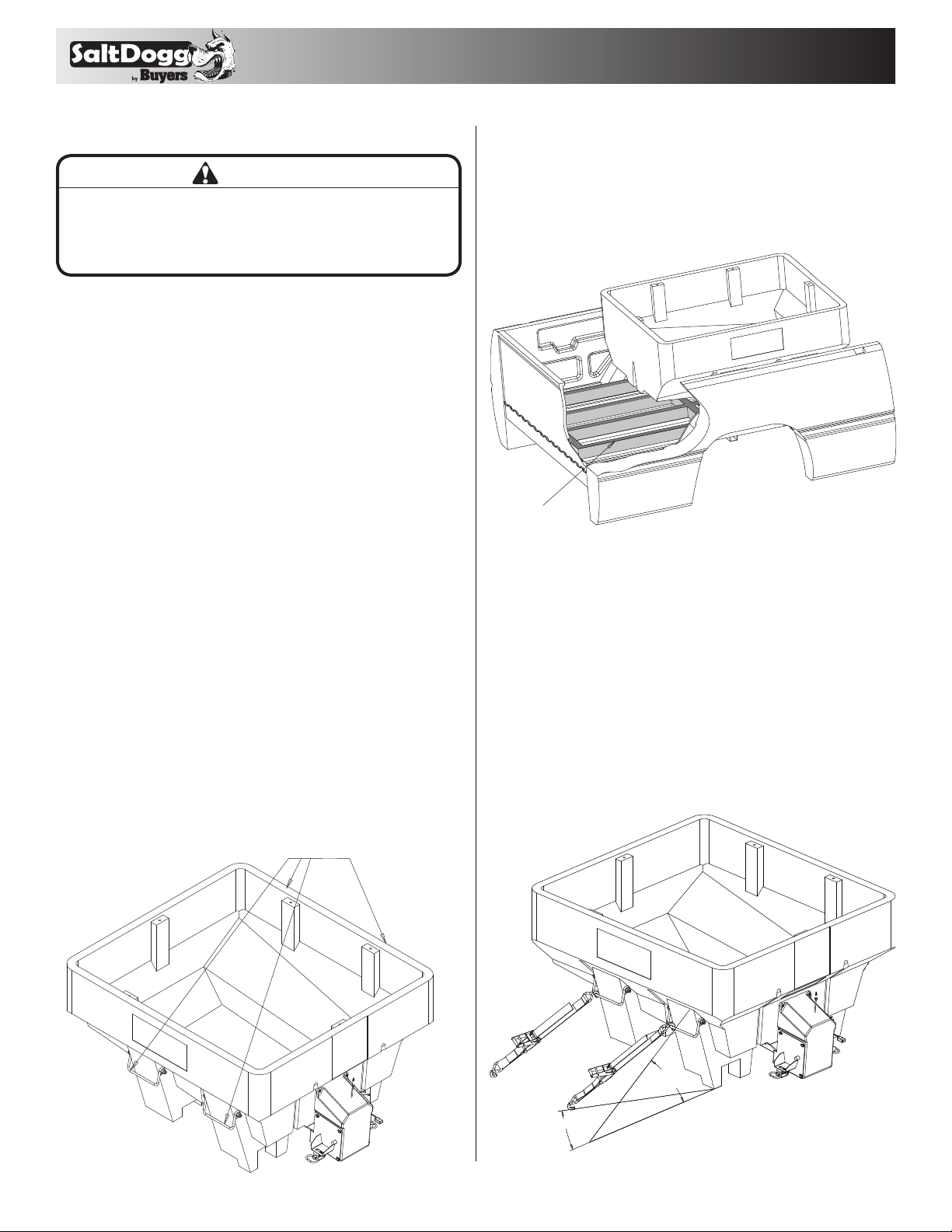
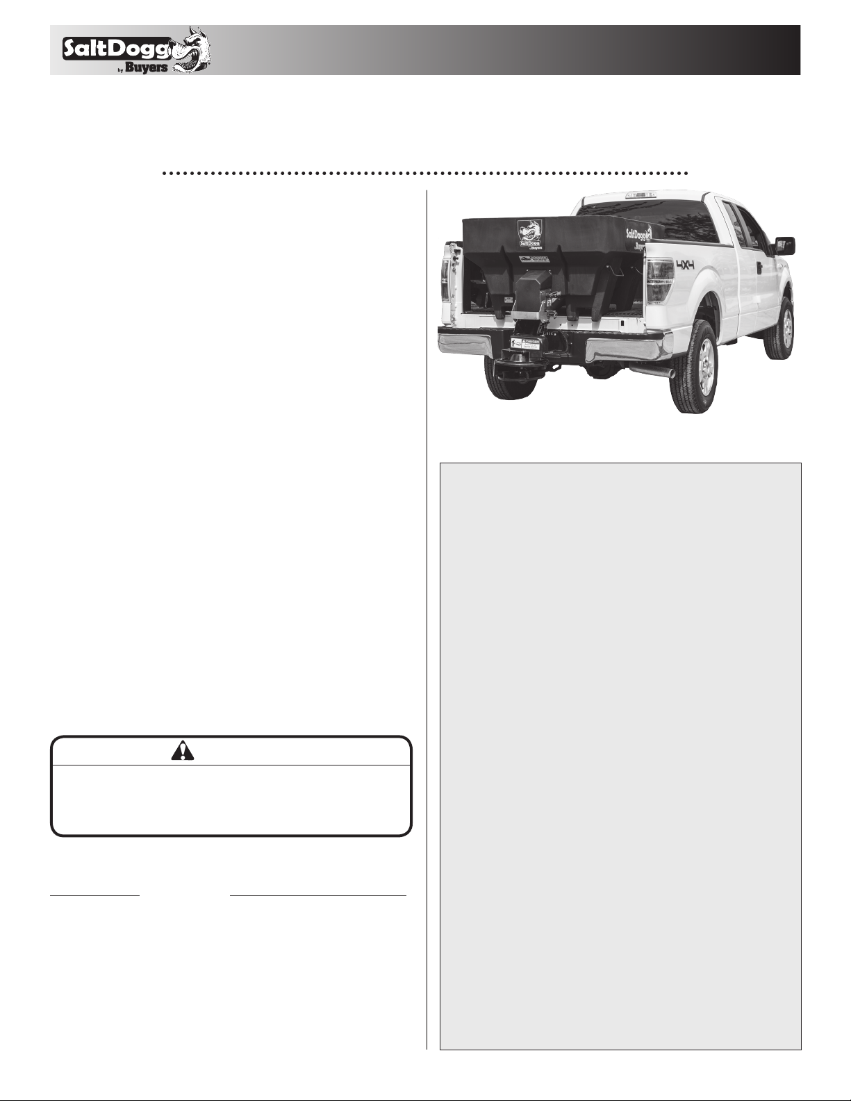
SHPE0750 Series SaltDogg®
Electric Drive Poly Hopper Spreader
0.65 cubic yard
U.S. PATENT 9,562,333
Table of Contents
General Information .....................................................................1
Warranty Information ...................................................................1
Safety Precautions ......................................................................2
Installation Instructions .............................................................2-3
Spreader Operation .....................................................................4
Spreader Maintenance.................................................................5
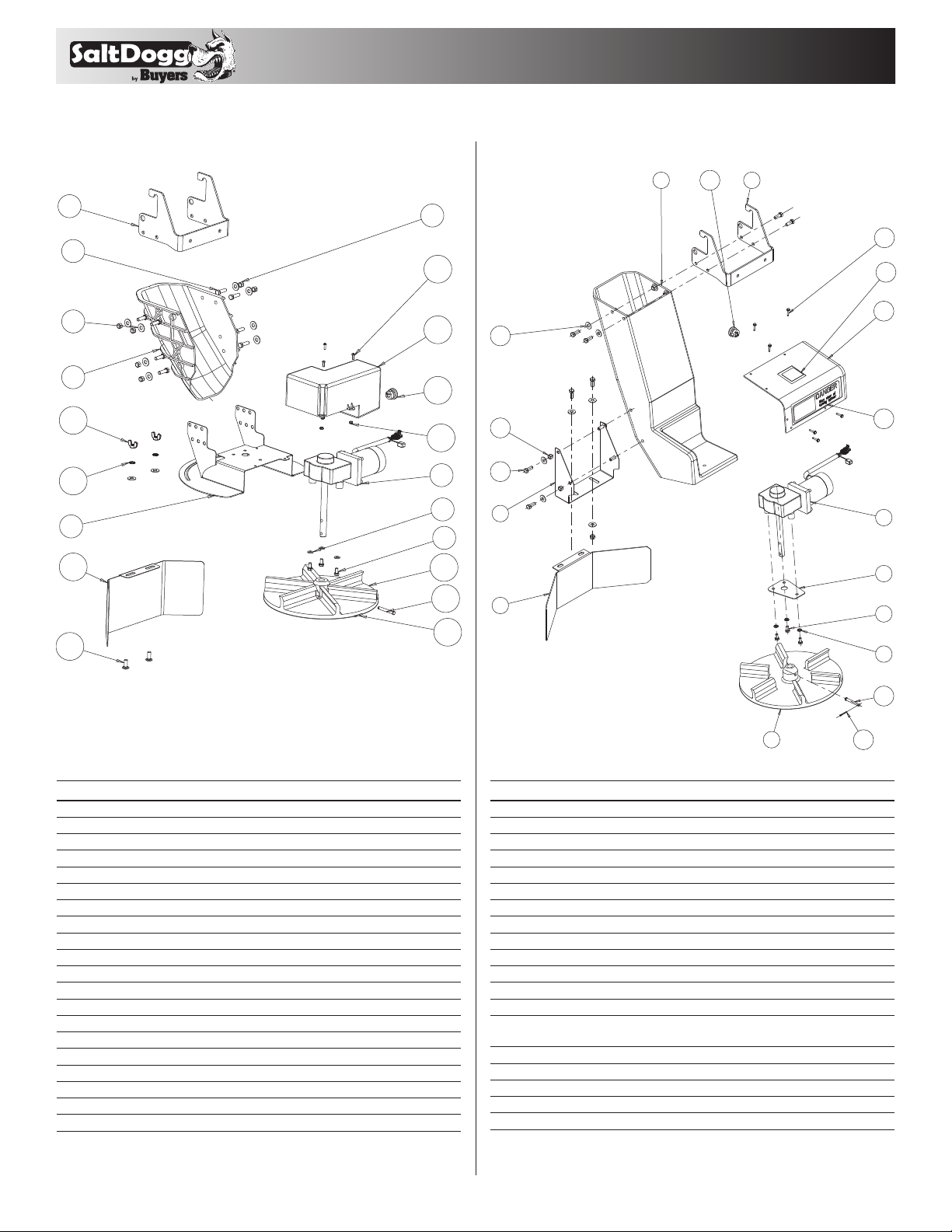
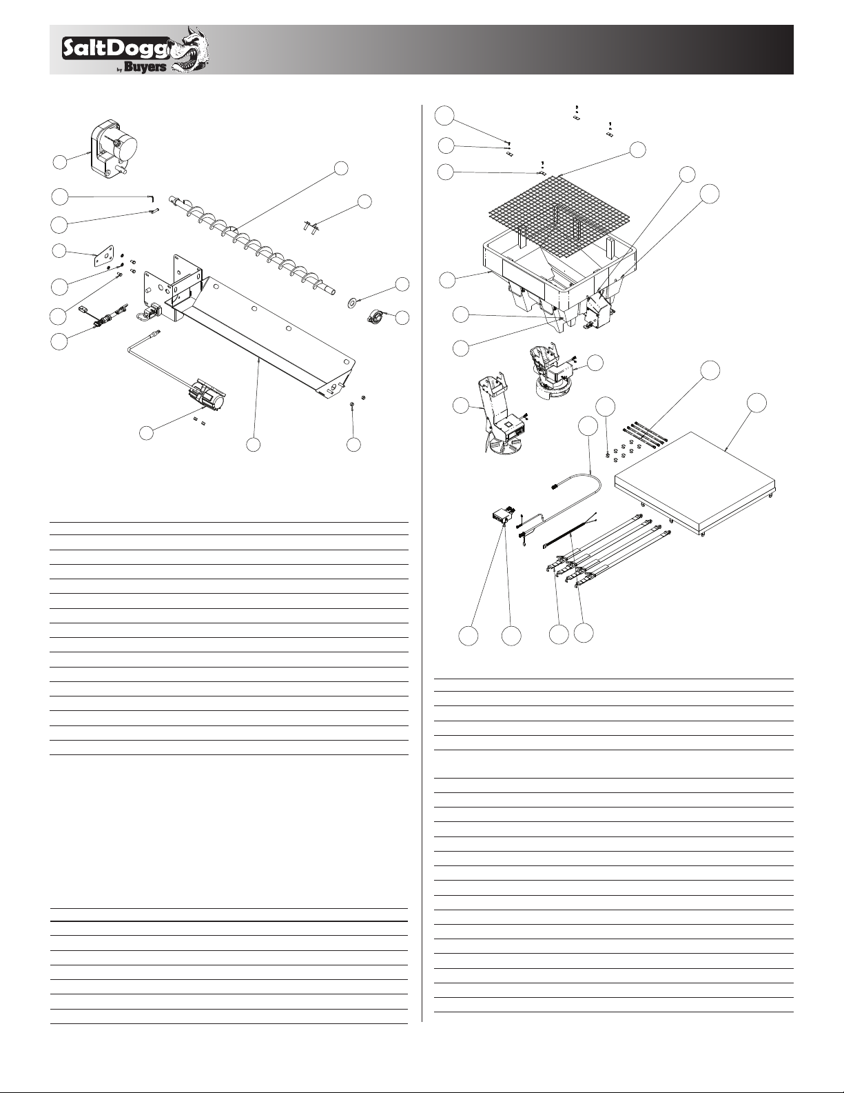
Repair Parts & Drawings .......................................................... 6-8
General Information
Spreader models:
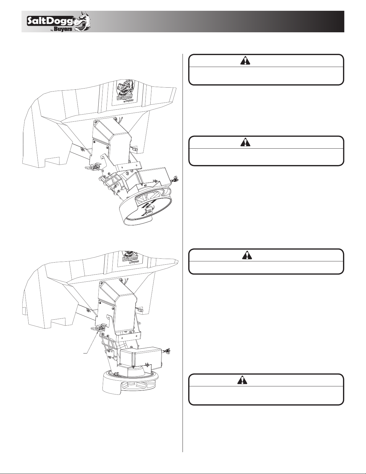
• SHPE0750- spreader with standard length chute
• SHPE0750X- spreader with extended length chute
Overall Length: 55-1/2 inches
Overall Width: 48 inches
Overall Height (installed): 28 inches
Empty Weight: 205 lbs (standard chute), 214 lbs (extended chute)
Capacity Struck: .65 cu. yd.
Average Installation Time: 3 hrs.
Vehicle Requirements:
½ ton pick-up truck or utility vehicle with 500 lbs.
capacity minimum.
Materials Recommended to Spread
Average Material Weights
Materials to use Weight (pounds per cubic yard)
Fine Salt-Dry 2,250
Coarse Salt-Dry 1,431
Sand/Salt up to 50/50 Mix-Dry 2,700
Note: To calculate the total spreader weight (including ice
control material), add the empty spreader weight plus the ice
control material and spreader accessories.
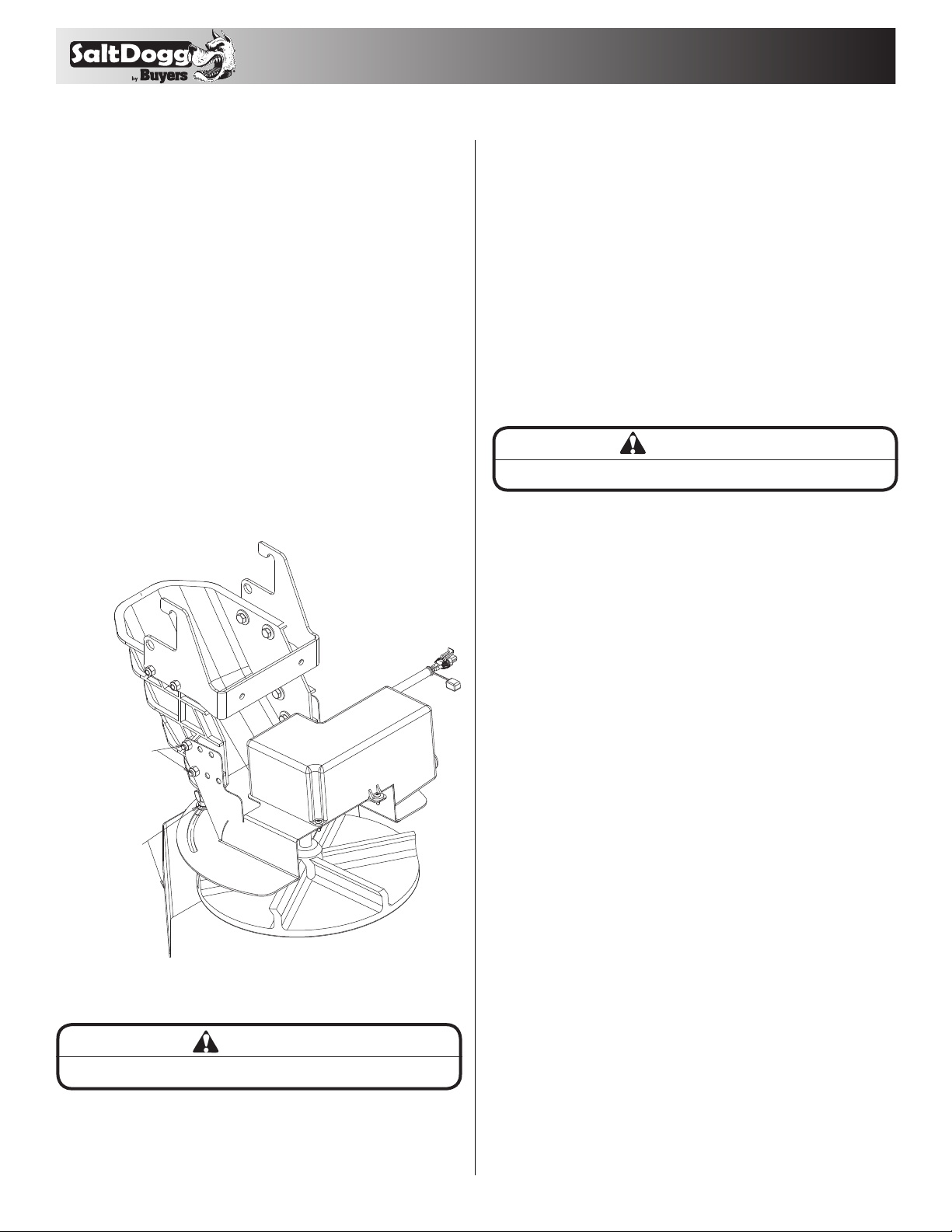
Installation Instructions