Salus iT500 Assembly instructions

iT500 User Reference Manual 5
GETTING STARTED
In the Box
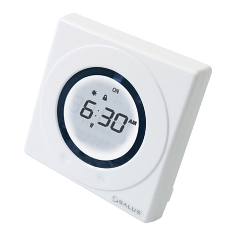
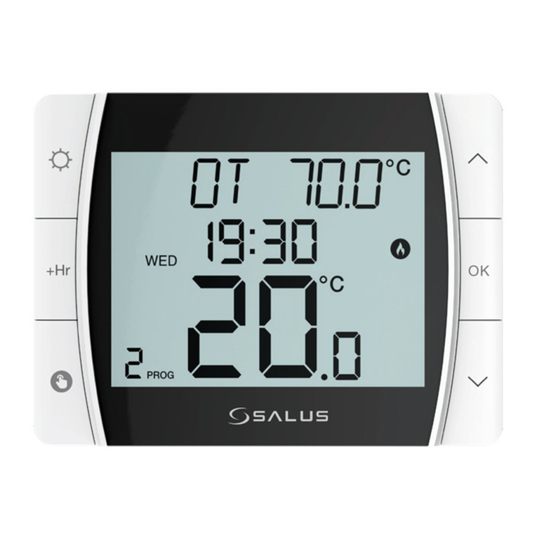
The iT500 Thermostat - replaces your xed hardwired thermostat and
also the timer or programmable part of your heating controller. This unit
communicates with the iT500RX Receiver. It can be located anywhere in your
home as it is portable and battery powered.
Includes: 2 x AA Alkaline Batteries.
The iT500RX Receiver - replaces the switching part of your timer or heating
controller that is hardwired to your boiler, pump and 3-way valve. It allows for
manual override in the event of failure of your iT500 Thermostat unit.
The iTG500 Gateway - connects to your router and enables you to control
your central heating and hot water controls from outside of your home, via a
smartphone or computer.
Includes: 12V Power Supply and Ethernet Cable
Optional Equipment
The iT300TX Temperature Sensor Transmitter - replaces the second
hardwired thermostat in a two zone heating system. It can be located in
any part of the zone as it is portable and battery powered, can also be wall
mounted.
Purchased separately.

iT500 User Reference Manual 7
Two Heating Zone Arrangement
In this arrangement, the two outputs on the iT500 Thermostat Receiver are used to control two zone heating
valves.
The temperature in Zone 2 is controlled by the addition of an iT300 Temperature Sensor Transmitter, placed
in the zone.
Boiler
iT500TR iT500RX
iT300TX
Zone 2
Zone 1
UPSTAIRS
RADIATORS
DOWNSTAIRS
RADIATORS
iT5
00
T
R
DO
R
A
T
30
0
TX
U
RA
iT500RX
e
1

iT500 User Reference Manual
8
Heating plus Hot Water Arrangement
This is the arrangement for installing an iT500 based control system with a single heating zone and hot water.
The iT500RX Receiver is hardwired to the heating and water system components.
The iT500 Thermostat is connected wirelessly to the iT500RX Receiver.
Hot
Water
Tank
Boiler
iT500 iT500RX
ALL RADIATORS
iT5
00
A
L
L
R
L
iT500RX

iT500 User Reference Manual 9
Connection to the Internet
To control the system via your smartphone or a remote computer, the system can optionally be connected to
the Internet. The iT500 Thermostat is connected to your existing broadband router, using the iTG500
Gateway.
iT500
Internet
iTG500
Router
i
TG500
Rou
iT500

iT500 User Reference Manual
20
Pairing the iT500 System Units for the First Time
Once the iT500 Thermostat and the iT500RX Receiver are physically installed, the two units need to be‘paired’.
Pairing allows the two devices to recognise each other and to communicate wirelessly.
When powering on the iT500TR Thermostat for the rst time, the Thermostat will go through the sequence
of screens shown below and automatically try and pair by searching for the strongest signal from an iTG500
Gateway.
The units attempt to pair for 10 minutes and during this time, the icon will ash. Pairing should take
approximately 20 seconds.
If the pairing is successful, the icon is turned on all the time.
If the pairing fails or times out, the icon will disappear and the system will retry later.
OTA (Over the Air) Software
Revision Number
All Display Icons
iT500 Software Revision
Number
Home Screen

iT500 User Reference Manual 21
Installing the iTG500 Gateway
Connecting to your Router
Using an RJ45 cable, connect the Gateway to your router (connected to the internet), connect the supplied
power cable to the Gateway and plug it into the 230V power supply. When all the connections are completed,
turn on the power supply. This is the rst step in enabling you to control your central heating from outside of
your home using your mobile phone or a remote computer.
The light on the router will ash red when it is rst connected and setting up. When connected to the SALUS
Controls Server it will display a constant green light.
Note: Check that your router is allowing the gateway access to both incoming and outgoing connections.
See your router’s operation manual for details on security and TCP/UDP port settings.
1. The gateway requires a xed IP address.
2. You require port 80 and 2165 UDP open.
3. Estimated use per month is 20mb.

iT500 User Reference Manual 23
CONTROLS AND DISPLAY
iT500TR Thermostat Keypad and Display
Keypad
The Thermostat keypad provides six keys for conguring and setting your heating and hot water system.
These are virtual keys, areas of the capacitive screen. An internal reset key is also provided for resetting the
unit.
Short press to conrm selection
Short press to return to previous
screen or previous item. In Program
Mode, long press to return to home
screen without saving. In Manual
Override Mode, long press to return to
Auto Mode. In Auto Mode, long press to
enter OUT mode.
Long press to enter Setting Mode.
In Setting Mode, short press to make
changes or save changes.
Scroll up/down a menu.
Increase/decrease a setting
value. Single press advances
value by a single digit. Holding
rolls value sequentially..
Reset Key (internal) Restores factory presets. In Setting
Mode, press and hold to cycle through current settings.
Display ON

iT500 User Reference Manual
24
Display
Notes:
• Indicators change during programming, becoming displays of selectable options or setpoint indicators.
• The and icons are not used on this model.
Indicates
unit is in Setting
Mode.
Indicates
internet
connection is
active.
Low battery
warning symbol.
If ashing, very
low battery.
Zone 1 Heating indicator
Heating on indicator
Cooling on indicator
Zone 2 Heating indicator
Heating on indicator
Cooling on indicator
Hot Water indicator
Hot Water on indicator - qualied below:
ON Continuously on
1On once a day from program 1 ON to program 3 OFF
AUTO Running in auto
OFF Continuously o
Indicates
wireless
communication
is active,
transmitting or
receiving.
Indicates
that the Holiday
override is
active.
Indicates that
the keypad is
locked. Press
and together
to unlock.
Indicates Frost Protection is
active, heating is on.
Temperature indicator, current
ambient temperature displayed
Days of the week, current day only
displayed
Clock, with 12/24 hour clock indication.
Program number, active program displayed Operation indicator

iT500 User Reference Manual 25
iT500RX Thermostat Receiver Controls
The iT500RX provides manual control of the system in the event that the wireless connection fails.
Ch Aux Ch/Aux
Auto Manual Off
Auto - Manual - O - switches
Auto -system controlled by
programs in iT500TR Control
Thermostat
Manual - system continuously on
O - system continuously o
Ch - Aux - Ch/Aux - switches
Should be set to match controlled
system i.e.:
Ch -heating only, 1 zone
Aux - heating only, 2 zones
Ch/Aux - heating (1 zone) plus
hot water
Other manuals for iT500
8
This manual suits for next models
3
Table of contents
Other Salus Temperature Controllers manuals