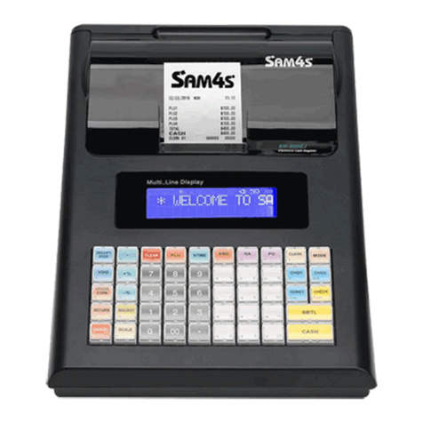
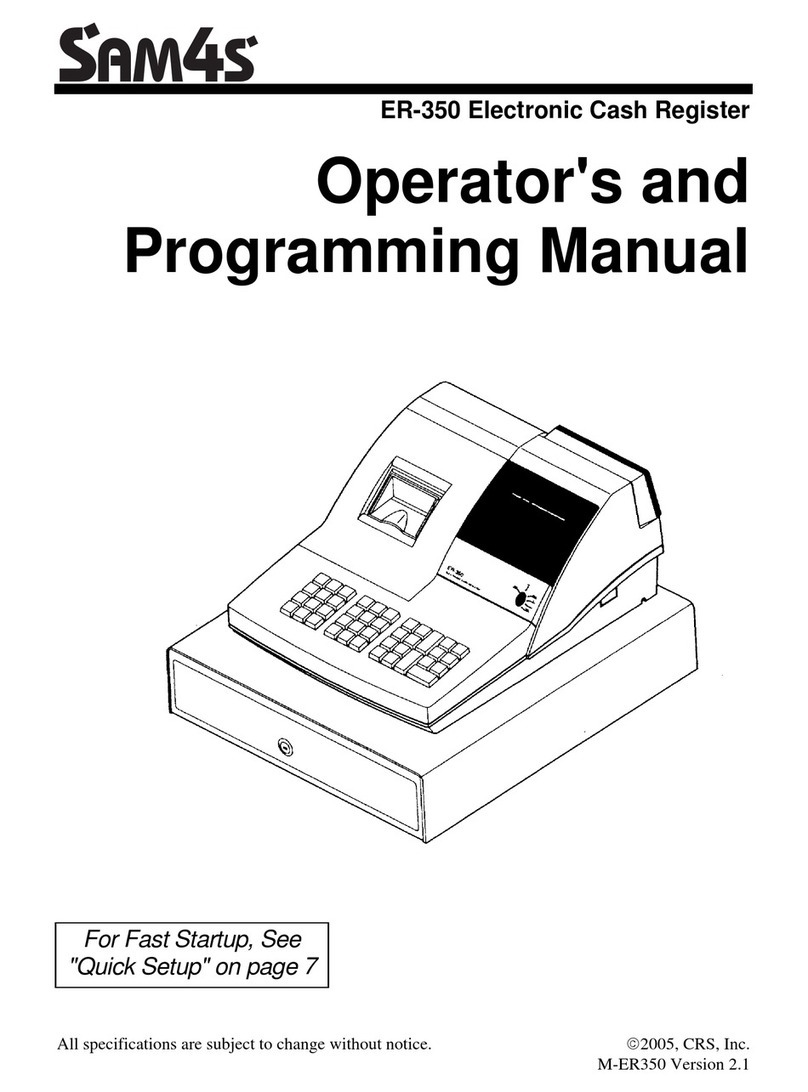
Sam4s ER-150 User manual

ELECTRONIC CASH REGISTER C O N T E N T S
ER-150
ELECTRONIC CASH REGISTER
Manual
1. Precaution Statements
2. Product Specifications
3. Installation and Operation
4. Assembly and Disassembly
5. Exploded View and Part List
6. PCB Layout and Part List
7. Block diagram
8. Wiring Diagram
9. Schematic Diagrams
SERVICE


Overview of this ECR
This service manual provides the technical information for many individual component systems, circuits and gives an
analysis of the operations performed by the circuits. If you need more technical information, please contact our service
branch or R&D center. Schematics and specifications provide the needed information for the accurate troubleshooting.
All information in this manual is subject to change without prior notice. Therefore, you must check the correspondence of
your manual with your machine. No part of this manual may be copied or reproduced in any form or by any means, without
the prior written consent of Shin Heung Precision .
Note: Before using this Electronic Cash Register (ECR) for the first time, leave please install the AA-Size Battery.
This allows the AA-Size battery, which maintains the memory of the ECR while the power is off, to charge
completely.
“Proper disposal of batteries is required. Refer to your local codes for disposal requirements.”

About this Manual
This service manual describes how to perform
hardware service maintenance for the SAM4S
ER-150 Electronic Cash Register.
Notes
Notes may appear anywhere in the manual.
They describe additional information about the
item.
Precaution symbols
. Indicates a Safety Precaution that applies to
this part component.
. Indicates the part or component is an
electro-statically sensitive device. Use caution
when handling these parts.

Copyright
ⓒ2004 by Shin Heung Precision.
All right reserved.
This manual may not, in whole or in part, be
copied, photocopied, reproduced, translated or
converted to any electronic or machine readable
from without prior written permission of Shin
Heung Precision .
SAM4S ER-150
Service Manual First edition.
March 2004.
V1.0
Printed in KOREA

SAM4S ER-150 1-1
1 Precaution Statements
Follow these safety, servicing and ESD precautions to prevent damage and to protect against potential hazards such as
electrical shock.
1-1 Safety Precautions
1. Be sure that all built-in protective devices are
replaced. Restore any missing protective shields.
2. When reinstalling the chassis and its assemblies, be
sure to restore all protective devices, including
nonmetallic control knobs and compartment covers.
3. Make sure there are no cabinet openings through
which people - particularly children - might insert
fingers and contact dangerous voltages.
Such openings include excessively wide cabinet
ventilation slots and improperly fitted covers and
drawers.
4. Design Alteration Warning:
Never alter or add to the mechanical or electrical
design of the ECR. Unauthorized alterations might
create a safety hazard. Also, any design changes or
additions will void the manufacturer’s warranty.
5. Components, parts and wiring that appear to have
overheated or that are otherwise damaged should be
replaced with parts that meet the original
specifications. Always determine the cause of
damage or over- heating, and correct any potential
hazards.
6. Observe the original lead dress, especially near the
following areas : sharp edges, and especially the AC
andhighvoltagesupplies.
Always inspect for pinched, out-of-place, or frayed
wiring. Do not change the spacing between comp-
onents and the printed circuit board. Check the AC
power cord for damage. Make sure that leads and
components do not touch thermally hot parts.
7. Product Safety Notice:
Some electrical and mechanical parts have special
safety-related characteristics which might not be
obviousfromvisualinspection.
These safety features and the protection they give
might be lost if the replacement component differs
from the original - even if the replacement is rated
for higher voltage, wattage, etc.
Components that are critical for safety are indicated
in the circuit diagram by shading, ( ) or ( ).
Use replacement components that have the same
ratings, especially for flame resistance and dielectric
strength specifications. A replacement part that
does not have the same safety characteristics as the
original might create shock, fire or other hazards.
CAUTION
Dangerous explosion if battery is incorrectly replaced.
Replace only with the same or equivalent type
recommended by the manufacturer.
Dispose used batteries according to the manufacturer’s
instructions.
ATTENTION
ll y a danger d’explosion s’il y a remplacement incorrect
de la batterie.
Remplacer uniquement avec une batterie du même type
ou d’un type équivalent recommandé par le constructeur.
Mettre au rebut les batteries usagées conformément aux
instructions du fabricant.

1 Precaution Statements
1-2 SAM4S ER-150
1-2 Servicing Precautions
WARNING: First read the-Safety Precautions-section of this manual. If some unforeseen circumstance creates a conflict
between the servicing and safety precautions, always follow the safety precautions.
WARNING: An electrolytic capacitor installed with the wrong polarity might explode.
1. Servicing precautions are printed on the cabinet.
Follow them.
2. Always unplug the units AC power cord from the AC
power source before attempting to:
(a) Remove or reinstall any component or assembly
(b) Disconnect an electrical plug or connector
(c) Connect a test component in parallel with an
electrolytic capacitor
3. Some components are raised above the printed circuit
board for safety. An insulation tube or tape is
sometimes used. The internal wiring is sometimes
clamped to prevent contact with thermally hot
components. Reinstall all such elements to their
original position.
4. After servicing, always check that the screws,
components and wiring have been correctly
reinstalled. Make sure that the portion around the
serviced part has not been damaged.
5. Check the insulation between the blades of the AC
plug and accessible conductive parts (examples metal
panels and input terminals).
6. InsulationCheckingProcedure:
Disconnect the power cord from the AC source and
turn the power switch ON. Connect an insulation
resistance meter (500V) to the blades of AC plug.
The insulation resistances between each blade of the
AC plug and accessible conductive parts (see above)
should be greater than 1 Mega Ohm.
7. Never defeat any of the B+ voltage interlocks.
Do not apply AC power to the unit (or any of its
assemblies) unless all solid-state heat sinks are
correctly installed.
8. Always connect an instrument’s ground lead to the
instrument chassis ground before connecting the
positive lead ; always remove the instrument’s ground
lead last.
1-3 Precautions for Electrostatic Sensitive Devices (ESDs)
1. Some semiconductor (solid state) devices are easily
damaged by static electricity. Such components are
called Electrostatic Sensitive Devices (ESDs);
examples include integrated circuits and some field-
effect transistors. The following techniques will reduce
the occurrence of component damage caused by static
electricity.
2. Immediately before handling any semiconductor
components or assemblies, drain the electrostatic
charge from your body by touching a known earth
ground. Alternatively, wear a discharging wrist-strap
device. (Be sure to remove it prior to applying power
- this is an electric shock precaution.)
3. After removing an ESD-equipped assembly, place it
on a conductive surface such as aluminum foil to
prevent accumulation of electrostatic charge.
4. Do not use Freon-Propelled chemicals. These can
generate electrical charges that damage ESDs.
5. Use only a grounded-tip soldering iron when
soldering or unsoldering ESDs.
6. Use only an anti-static solder removal device. Many
solder removal devices are not rated as anti-static;
these can accumulate sufficient electrical charge to
damage ESDs.
7. Do not remove a replacement ESD from its protective
package until you are ready to install it. Most
replacement ESDs are packaged with leads that are
electrically shorted together by conductive foam,
aluminum foil or other conductive materials.
8. Immediately before removing the protective material
from the leads of a replacement ESD, touch the
protective material to the chassis or circuit assembly
into which the device will be installed.
9. Minimize body motions when handling unpackaged
replacement ESDs. Motions such as brushing clothe
together, or lifting a foot from a carpeted floor can
generate enough static electricity to damage an ESD.
SAM4S ER-150 2-1
2 Product Specifications
Specifications are correct at the time of printing. Product specifications are subject to change without notice. See below
for product specifications.
2-1 General Specification
2-1 A. System Specifications
Item Description Remark
AC Power Source AC120V / 60Hz
AC230V / 50Hz
USA
Europe
Rating 8W USA and Europe
Printer M-42V Refer to Printer
Specification on next page
Battery AA-Size (*2)
Processor SEM100 (64pin) Masked Processor
Memory 61408
Display Front : 9-digits display (Window Display)
Rear : 9-digits display (Rear Display)
Optional
Key Board 26 Keys
Drawer
4C3B,4C4B
Weight : 3.3kg
Dimensions : 420(L) x 325(W) x 95(H)
Millimeters
Set Weight : 5.6kg
Dimensions : 420(L) x 325(W) x 225(H) Millimeters
※Equipment specifications and design are subject to change without notice.

2 Product Specifications
2-2 SAM4S ER-150
2-1 B. Printer Specifications
Item Description Remark
Printing System Print wheel selecting type serial printer
Print Column Capacity 19 column max.
Character Position System column 13 positions + 1 empty position
Numeral column 14 positions
Character Size 1.6mm (W) x 2.2mm (H)
Character Space
Column Space
Line Space
2.1mm between numeric, 2.6mm between numeric and
symbol, 2.4mm between symbols
4.6mm
Printing Speed
19 Columns
7 Columns
Approx. 0.9 Line/sec
Approx. 2.2 Line/sec
Average speed
At 6.0 Vdc
Printing Paper Roll
Type Paper
Paper Width
Outside Diameter
Paper Thickness
Basic Weight
Ordinary type
57.5 ±0.5 mm
Φ80mm or below
0.06 ~ 0.85mm
47 ~ 64 g/㎡(40 ~ 55 kg/1000 sheets/1091 x 788mm)
Paper Feeding Quick feed
Approx. 8 Line/sec, Paper release mechanism attached.
Ink Roll
Color
Life
Standard
Purple or Black
Refer to the separate “Specifications of Model 42V”
IR-40
Motor
Terminal Voltage
Mean Current
6.0 (+0.5 / -2.0) Vdc
Approx, 0.25A
At 6.0Vdx, 25℃
19 columns 7
character shift printing
Detector
Mechanical contact
Reset pulse signal R, timing pulse signal T, timing auxiliary
Pulse signal t
Trigger Coil (magnet)
Terminal Voltage
Direct
Current Resistance
6.0 (+0.5 / -2.0) Vdc
Approx. 20Ω(25℃)
connection Printer Side Jumper Wire
Guaranteed Operating
Temperature
0℃~ 50℃
Reliability (MCBF) 700,00 columns
Overall Dimensions 86mm (W) x 50mm(D) x 19mm (H)
Weight Approx. 90g
※Equipment specifications and design are subject to change without notice.

2 Product Specifications
SAM4S ER-150 2-3
2-2 Appearance
2-2 A. Appearance Dimensions (mm)
2-2 B. ECR Features
①Cover Printer
②Key Board
③Drawer
④Window display
⑤Case Upper
⑥Power Cord

2 Product Specifications
2-4 SAM4S ER-150
Memo

SAM4S ER-150 3-1
3 Installation and Operation
This chapter details the method for installing the ECR system and shows the locations various feature items.
3-1 Installation
3-1 A. System Reset Procedure (ALL CLEAR)
WARNING: You should not do this procedure after installation or battery exchanging. If you do xo, all preset data
and total sums may be lost.
When first installing the machine, the battery exchanging or other maintenance which performed under the condition that
the battery connector is plugged off, the System Reset must be performed before operation.
Plug in, while pressing the c and 00 keys in 3 seconds at P mode. Then, ER-150 system will be reset and all data
will be cleared.
3-1 B. Battery Insertion and Exchange
WARNING: If yow put off this battery while using the machine, it changes the commercial data and values that
are preset
Open the Printer cover, you can find a case of battery or its cover at the under of the paper spool. Insert two AA size 1.5V
batteries and the cover plate applied by us or your new equivalent batteries according to “+,-“marking. After the battery
cover inserted, you should write the date will be exchanged the battery for the maintenance.

3 Installation and Operation
3-2 SAM4S ER-150
3-2 Operation
3-2 A. Mode Switch
The position of the Key in the Node Switch determines the action of the ECR. Table 3-1 shows the various mofes that are
available.
Mode Function
OFF Operation stop
R Sales Operation
X X-level report generation
Z Z-level report generation
P Program mode
Table 3-1 ECR Modes Figure 3-1 Mode Key Switch
3-2 B. Keyboard Matrix
The ER-150 ECR offers keyboard, 26-key, as shown in Table 3-2.
Model Keys Type
ER-150 26 Rubber
Table 3-2 Keyboard Types
OFF
R
X
Z
P

SAM4S ER-150 4-1
4 Assembly and Disassembly
This chapter describes the Disassembling and Reassembling procedures for ER-150, Electronic Cash Register.
WARNING: This ECR contains electro-statically sensitive devices.
Use caution when handling any components in this system.
4-1 Disassembly
CAUTION: Disconnect the ECR from the external power source before Disassembly. The following directions
are given for the ER-150.
4-1 A. Case-upper Disassemble and M-42V Disassemble Procedure
C.F.) The Chapter 5-1 Total Disassembly.
1. Lift off Cover-printer (A).(Page 5-1)
2. Remove two screws (C-8) on Case-upper(C-9) and pull it front and up, then the Case-upper(C-9)
will be open.(Page 5-5)
3. Remove the Power connector (c) on the Main PCB (C-19), and Drawer connector (h) on the Drawer.
(Page 5-5, 5-7)
4. Remove the Drawer (D-1). (Page 5-7)
5. Remove the Battery connector (q) on the Main PCB(C-19). (Page 5-5)
6. Remove the Printer connector Harness (g). (Page 5-5)
7. Remove the Spool motor connector (f) on the main PCB. (Page 5-5)
8. Remove the screws (C-22) on the Case-upper(C-9). (Page 5-5)
9. Remove the Plate Main PCB (C-20). (Page 5-5)
4-1 B. Reassemble Procedure
- Reassemble procedures is reverse procedures of the upper 4-1-1 procedure.

4 Assembly and Disassembly
4-2 SAM4S ER-150
Memo

SAM4S ER-150 5-1
5 Exploded View and Parts List
Figure5-1 Total Disassembly

5 Exploded View and Parts List
5-2 SAM4SER-150
Figure5-2 A. ASS’Y COVER-PRINTER
A. ASS’Y COVER PRINTER
No Parts-No. Description/Specification Q'ty Design-Location Serviceable Remark
JK97-00924A MEA COVER-PRINT:ER-150,BASIC,WORLD 1 Y
JK70-10320A IPR-CUTTER PAPER:ER-150,STS304,T0.3 1 N
A
JK72-40928B PMO-COVER PRINTER:ER-150,SAM4S 1 N

5 Exploded View and Parts List
SAM4S ER-150 5-3
Figure5-3 B. ASS’Y-PRINTER

5 Exploded View and Parts List
5-4 SAM4SER-150
B. ASS’Y-PRINTER
No Part-No Description / Specification Q'TY Design-location Remark
B JK59-10120A UNIT-PRINTER:ER-150,M-42V 1
101 JK81-10994A AS-RUBBER FITTING (F801001050) 1
102 JK81-10995A AS-MOTOR (F816051010) 1
103 JK81-10996A AS-MOTOR GEAR (F817051010) 1
105 JK81-10997A AS-CUP SCREW (B040352118) 1
106 JK81-10998A AS-P/F DRIVE GEAR ASSY (F815101000) 1
107 JK81-10999A AS-DETECTOR ASSY (F815151000) 1
108 JK81-11000A AS-DETECTION WHEEL (1024276) 1
109 JK81-11001A AS-PRINT WHEEL SHAFT (1017190) 1
110 JK81-11002A AS-PRT WHEEL SPRING (F801202020) 1
111 JK81-11003A AS-RETAINING RING (B150300311) 1
112 JK81-11004A AS-PRINTER-WHEEL ASSY 1-6 (M817001060) 1
120 JK81-11005A AS-H/TRAN LEVER ASSY (F815210000) 1
130 JK81-11006A AS-CARRIAGE (F817208010) 1
140 JK81-11007A AS-HAMMER (F809201020) 1
150 JK81-11008A AS-HAMMER RET/SPRING (F808201020) 1
160 JK81-11009A AS-PRINT CAM (F817201020) 1
118 JK81-11010A AS-CARRIAGE SPRING (F812201020) 1
119 JK81-11011A AS-INK ROLL SPRING (F817201010) 1
120 JK81-11012A AS-SELE PAWL SPRING (F818209010) 1
122 JK81-11013A AS-P/F TRANS GEAR (F815212010) 1
123 JK81-11014A AS-P/F RATCHET WHEEL (F801202030) 1
124 JK81-11015A AS-PRT CHANGE OVER CAM (F817203020) 1
125 JK81-11016A AS-PLANET GEAR (F801206020) 1
126 JK81-11017A AS-SEL DRIVE GEAR (F801206030) 1
127 JK81-11018A AS-REDUCTION GEAR (F817203010) 1
128 JK81-11019A AS-RETAINING RING (B150300212) 1
129 JK81-11020A AS-COIL S/GEAR ASSY (1041872) 1
130 JK81-11021A AS-RETAINING RING (B150300311) 1
131 JK81-11022A AS-POSITIONING SHAFT (F806206010) 1
132 JK81-11023A AS-POSITIONING PLATE (F808205010) 1
133 JK81-11024A AS-SELECTING RATCHET (F804204010) 1
134 JK81-11025A AS-TRIGGER L/SPRING (F803204020) 1
135 JK81-11026A AS-RETURN LEVER (F815207010) 1
137 JK81-11027A AS-TRIGGER PLATE (1017206) 1
138 JK81-11028A AS-TRIGGER PLATE SPR (F801205110) 1
139 JK81-11029A AS-RETURN LEVER SPR (F810205020) 1
140 JK81-11030A AS-TRIGGER LEVER (F801205060) 1
141 JK81-11031A AS-PRINT SHAFT (1017209) 1
142 JK81-11032A AS-CARRIAGE F/GEAR (F801211020) 1
143 JK81-11033A AS-PLATEN ASSY (1024287) 1
144 JK81-11034A AS-JUMPER WIRE (1018148) 1
145 JK81-11035A AS-PLAIN WASHER (F817210010) 1
151 JK81-11036A AS-S/PAWL SPR HOLDER (F818202020) 1
152 JK81-11037A AS-CUP SCREW (B040351111) 1
Note: ( ) means the Printer Manufacture’s Parts List (EPSON’s Parts List)

5 Exploded View and Parts List
SAM4S ER-150 5-5
Figure5-4 C. ASS’Y CASE-UPPER
Table of contents
Other Sam4s Cash Register manuals

Sam4s
Sam4s ER-390M Owner's manual

Sam4s
Sam4s ER-180T Owner's manual

Sam4s
Sam4s ER-5200 Troubleshooting guide

Sam4s
Sam4s NR-500 Series Owner's manual

Sam4s
Sam4s ER-230 Series Troubleshooting guide

Sam4s
Sam4s ER-650 User manual

Sam4s
Sam4s ER-180 User manual

Sam4s
Sam4s SER-7000 User manual

Sam4s
Sam4s ER-420 Series User manual

Sam4s
Sam4s ER-900 Series User manual

Sam4s
Sam4s ER-380M Troubleshooting guide

Sam4s
Sam4s ER-180 Owner's manual

Sam4s
Sam4s ER-390M User manual

Sam4s
Sam4s ER-230EJ User manual

Sam4s
Sam4s ER-420M Troubleshooting guide

Sam4s
Sam4s ER-5100? SERIES User manual

Sam4s
Sam4s ER-260EJ Owner's manual

Sam4s
Sam4s SER-7000 User manual

Sam4s
Sam4s SPS-520 Assembly instructions

Sam4s
Sam4s ER-650 User manual