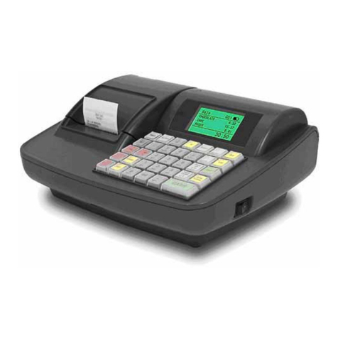
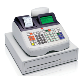
Uniwell LX-5700 Operating instructions

LX-5700
LX-5750
[LX5700]DRE-100 [MKII]
R
RE
EP
PA
AI
IR
R
M
MA
AN
NU
UA
AL
L

Caution Before Repairing
1. Please make sure that the AC cord plug is disconnected from the power
supply socket before repairing. Because all parts on the ECR are still in
the power-on condition even if the control key is turned to the Lock position,
so the followings happen sometimes when AC cord plug is connected:
1) If you touch some parts, you may have an electric shock.
2) If the board is removed, the board may be broken.
2. The batteries are installed on the MPU board so, do not put the removed
MPU boards on the conductive material (steel, etc.).
If the battery is shorted, all preset data is deleted and the board may be
broken depending on the case.
3. Many C-MOS LSI/ICs are used for the MPU board, interface board, etc.
These ICs are sensitive about static electricity so they are easy to be
damaged. Before touching the MPU board, interface board, etc, please
discharge static electricity of your hands first.
4. After repairing, please be sure to re-connect the ground wires where they
used to be. Otherwise, the noise proof cannot be effective.
5. Please be sure to do the initial reset operation after repairing.
6. Battery replacement
This machine has been equipped with the Nickel- Metal Hydride battery to
keep the contents of memories. At the time of battery replacement, it must
be replaced as follows.
Ni-MH BATTERY:
MODEL:
TYPE:
MANUFACTURER:
RATING:
GP80BVH3AMX
Nickel-Metal Hydride Battery
GPI International LTD.
3.6V,80mAH
CAUTION DANGER OF EXPLOSION IF BATTERY IS INCORRECTLY REPLACED. REPLACE ONLY WITH
THE SAME OR EQUIVALENT TYPE RECOMMENDED BY THE MANUFACTURER.
DISCARD USED BATTERIES ACCORDING TO THE MANUFACTURER'S INSTRUCTION.
ATTENTION DANGER D'EXPLOSION EN CAS DE REMPLACEMENT INCORRECT DE LA BATTERIE.
REMPLACER UNIQUEMENT PAR UNE BATTERIE DU MEME TYPE OU D'UN
TYPERECOMMANDE PAR LE CONSTRUCTEUR. METTRE AU REBUT LES BATTERIES USEES
CONFORMEMENT AUX INSTRUCTIONS DU FABRICANT.
VORSICHT EXPLOSIONGEFAHR, WENN BATTERIE FALSCH EINGESETZT WIRD. NUR DURCH
BATTERIE DESSELBEN ODER VOM HERSTELLER EMPFOHLENEN GLEICHWERTIGEN TYPS
ERSETZEN. GEBRAUHTE BATTERIEN NACH ANWEISUNG DES HERSTELLERS ENTSORGEN.
TABLE OF CONTENTS
I. GENERAL EXPLANATION
1. CONNECTION DIAGRAM ...................................................................................................................... 1
II. TERMINAL LIST OF PRINTER
1. M-T207A(011) / M-T203(011) ............................................................................................................1
1-1. Connector Pin Arrangement ........................................................................................................................1
1-2. Connector Pin Assignments .........................................................................................................................1
1-3. Connector Pin Assignment of Cutter Motor................................................................................................1
III. ILLUSTRATION OF ECR ASSEMBLY & MACHINE PARTS LIST
ILLUSTRATION OF ECR ASSEMBLY ......................................................................................................... 1
MACHINE PARTS LIST ........................................................................................................................... 14
DIFFERENCE BETWEEN LX-57XX MKII MODEL AND OLD MODEL........................................................ 17
IV. UNIT PARTS LIST
1. MPU UNIT UE3-1 (131) / MPU UNIT UE3-2 (131) ........................................................................1
2. PRT UNIT 101 (LX)...........................................................................................................................4
V. RECOMMENDED PARTS LIST
1. MACHINE............................................................................................................................................. 1
VI. DRAWING LIST
Unit name Circuit name Revision Page
POWER / MPU BLOCK CIRCUIT
ASSEMBLY CIRCUIT 1.07 1/10
POWER SUPPLY CIRCUIT 1.07 2/10
MPU CIRCUIT 1.07 3/10
MEMORY CIRCUIT 1.07 4/10
LCD CONTROL CIRCUIT 1.07 5/10
IO CIRCUIT 1.07 6/10
RT UNIT 311 SERIAL CIRCUIT 1.07 7/10
KEYBOARD CIRCUIT 1.07 8/10
PRINTER CONTROL CIRCUIT 1.07 9/10
MPU UNIT UE3 (131)
PRINTER DRIVER CIRCUIT
MPU131-C
1.07 10/10
PRINTER IF
PRT UNIT 101 PRINTER I/F CIRCUIT PRT101-A 1.10 1/1
KEYBOARD UNIT CIRCUIT
STROKE KEYBOARD 020401 1/1KEYBOARD
FLAT KEYBOARD 020401 1/1

Drawer2
(Option)
MPU UNIT UE3-1 (131) MKII
or
MPU UNIT UE3-2 (131) MKII
Stroke Keyboard
Main ROM
PRT CTL ROM
RT UNIT 311
CN4
CN5
CH-A
(RS485)
RJ-45
CH-B
(RS232C)
DSUB-9P
CN54
Drawer1
Drawer Sensor
(Option)
FUSE
F.GND
Transformer
CH-E
(RS232C)
DSUB-9P
RT UNIT 101
(Option)
CN5
-
CH-D
(RS232C)
DSUB-9P
RT UNIT 101
(Option)
CN5
-
CN2
CN3
IF UNIT 071
(Option)
I. GENERAL EXPLANATION
1. Connection Diagram
General Explanation - 1
CN3
CN12
CN13
CN16
CN11
CN6CN5
Rear Display Unit
CN1
MR UNIT 021
(Option)
CN17
CN23
CN9
CN18
Control Lock
CN8
CN10
CN19
Flat Keyboard
LED
CN20
CN24
CN22
LCD
PRINTER RELATION
UNIT UE1
PRT UNIT 101 (LX)
Journal Printer
Receipt Printer
CN25

Terminal List of Printer - 1
II. TERMINAL LIST OF PRINTER
1. M-T207A(011) / M-T203(011)
1-1. Connector Pin Arrangement
1-2. Connector Pin Assignments
Pin No. Circuit Pin No. Circuit Pin No. Circuit Pin No. Circuit Pin No. Circuit
1 Motor A 6 Cutter signal 11 N.C 16 Vdd 21 /STB1
2 Motor /A 7 Platen open signal 12 VH 17 GND 22 /LAT
3 Motor B 8 Paper end signal 13 DI 18 GND 23 CLK
4 Motor /B 9 LED (K) Paper end 14 /STB2 19 GND 24 VH
5 N.C 10 Vdd (detector) 15 /STB3 20 TM 25 VH
1-3. Connector Pin Assignment of Cutter Motor
9
Cutter signal
(Connection diagram)
10
8
7
6
Platen open signal
Paper end signal
LED (K) Paper end
Vdd
25pin 1pin 25pin 1pin
M-T207A(011) M-T203(011)
2
1
3 4
A A
B
B
Motor
(Connection diagram)

III. ILLUSTRATION OF ECR ASSEMBLY & MACHINE PARTS LIST

1 17
1 14
1 11
1 8
1 7
1 18
115
1 12
1 9
1 19
1 16
113
1 10
1 20
1 220
1 520
1 320
1 420
1 120
1 6
1 5
1 22
1 23
1 24
1 4
1 3
1 2
T2W(3X8)
T1P(2X8)
Illustration of ECR Assembly & Machine Parts List - 1
1
Stroke Keyboard
1 21
1 1

1 3
1 1
1 2
1
Flat Keyboard
Illustration of ECR Assembly & Machine Parts List - 2

2
2
2A 2B
Stroke Keyboard
Flat Keyboard
B(M4X8)
B(M4X8)
Illustration of ECR Assembly & Machine Parts List - 3

3 2
3 1 3 3
3
Illustration of ECR Assembly & Machine Parts List - 4

4 5
4 4
4 3
4 2
4 7 4 8
4 1
4
Rear Display Unit
Illustration of ECR Assembly & Machine Parts List - 5

W(M2.3X10)
5 7
5 5
5 4
5 3
5 2
NUT M2.3
5 1
5 6
Illustration of ECR Assembly & Machine Parts List - 6

X
MA
Z
61
2
62
2
63
2
6 2
6 1
6
T2F(2.6X10)
Illustration of ECR Assembly & Machine Parts List - 7

7 3 7 1
7 2
P(M4X4)
P(M4X6)NI
Illustration of ECR Assembly & Machine Parts List - 8

B(M4X8)
M4TW
8 2
P(M3X6)
M3PW 8X1.0 (insulation)
Illustration of ECR Assembly & Machine Parts List - 9
8 1

9 1
9
B(M4X8)
M4TW P(M4X8)SP
Illustration of ECR Assembly & Machine Parts List - 10

W(3X8)
T3B(3X6)
T2P(3X6)
T2P(3X10)
10 1
10 2
10 3
10 4
10 5
10 6
Illustration of ECR Assembly & Machine Parts List - 11

Illustration of ECR Assembly & Machine Parts List - 12
W(3X8)
T3B(3X6)
T2P(3X10) T2P(3X6)
10 1
10 7
10 8
10 3
10 9
10 6
10 5
10 1A
10 2
10 4
T2P(3X6)

11 30
11 29
11 1
11 15
11 14
11 16
11 13
11 19
11 12
11 39
11 37
11 38
11 8
11 7
11 11
11 5 11 4
11 10
11 6 11 2
11 25
11 26
11 28
11 21
11 20
11 33
11 34
11 35
11 36
11
11A
11 22
11 23
11 24
11 27
11 3
11 31
11 32
11 17
P(M3X15)
P(M4X15) P(M4X6)
P(M3X6)S
P(M3X6)
T1W(3X6)
P(M3X6)
M3TW
M6.2TW 0.6
M6.2TW 1.2
M3PW 8X0.5
M4PW 9X0.6
Illustration of ECR Assembly & Machine Parts List - 13

Illustration of ECR Assembly & Machine Parts List - 14
Machine Parts List – 1/3
NUMBER REF.# PARTS NAME Q'TY Used for
1 57168 STROKE KEYBOARD GRAY 3RD 1 ®
1- 1 57169 KEYBOARD STAND GREY 3RD 1
1- 2 57170 SINGLE KEY TOP 3RD 45
1- 3 57171 LABEL KB 56/57-02/05 1
1- 4 57172 SINGLE KEY CAP 3RD 45
1- 5 57173 DOUBLE KEY TOP 3RD 1
1- 6 57174 DOUBLE KEY CAP 3RD 1
1- 7 57175 DUMMY KEY GRAY 3RD 5
1- 8 57176 TEN KEY 0 GRAY 3RD 1
1- 9 57177 TEN KEY 00 GRAY 3RD 1
1-10 57178 TEN KEY . GRAY 3RD 1
1-11 57179 TEN KEY 1 GRAY 3RD 1
1-12 57180 TEN KEY 2 GRAY 3RD 1
1-13 57181 TEN KEY 3 GRAY 3RD 1
1-14 57182 TEN KEY 4 GRAY 3RD 1
1-15 57183 TEN KEY 5 GRAY 3RD 1
1-16 57184 TEN KEY 6 GRAY 3RD 1
1-17 57185 TEN KEY 7 GRAY 3RD 1
1-18 57186 TEN KEY 8 GRAY 3RD 1
1-19 57187 TEN KEY 9 GRAY 3RD 1
1-20 57144 KEYBOARD ASSY 1 ®
1-20-1 57145 PCB KEYBOARD NEW 1
1-20-2 34013 INSU LOCK TIE T18R 1
1-20-3 57024 FERRITE CORE ID15 OD25 K5 1
1-20-4 57025 WIRE ASSY UL1007 L340X08 26# 1
1-20-5 57026 WIRE ASSY UL1007 L340X10 26# 1
1-21 57188 SILICON RUBBER KEY 3RD 1 ®
1-22 57189 DOUBLE KEY SHAFT LINK 3RD 1
1-23 57190 HOOK RIGHT FOR DOUBLE KEY WH 1
1-24 57191 HOOK LEFT FOR DOUBLE KEY BK 1
Stroke keyboard
1- 1 57165 FLAT KEY EMBOSS SHEET 1 Flat Keyboard ®
57166 FLAT KEY SHEET 56/57-02 1 Soft: 05
1- 2 57167 FLAT KEY SHEET 56/57-05 1 Soft: 02
1- 3 57031 FLAT KEYBOARD MEMBRANE 1 ®
2 57032 UPPER HOUSING STROKE GRAY 1
2A 57034 MAGNET PLATE 1
2B 57248 CONTROL LOCK PLATE LX-5700 1
Stroke keyboard
2 57033 UPPER HOUSING FLAT GRAY 1 Flat Keyboard
3 57224 PRINTER COVER LX5750 ASSY 1 LX-5750
57225 PRINTER COVER LX5700 ASSY 1 LX-5700
3-1 57037 PRINTER COVER NX5400 1
3-2 57038 VALIDATION COVER GRAY 1
57231 VALIDATION LENS T-1P 1 LX-5750
3-3
57232 VALIDATION LENS T-2P 1 LX-5700
4 57040 REAR DISPLAY UNIT UE1 1 ®
4-2 57042 PCB REAR DISPLAY UE1 1
4-3 57043 SPON T2 L10W10 1
4-4 57044 VFD SH121MAB FOOT 10MM 1
4-7 57046 WIRE ASSY UL1007 L440X14 26# 1
4-8 57047 WIRE ASSY UL1007 L440X15 26# 1
4-1 57041 REAR DISPLAY HOLDER GRAY 1
4-5 57045 REAR DISPLAY LENS NX5400 1
5-1 57193 WIRE ASSY UL1007 L300 MMX2 26# 1
5-2 57194 LED SPACER D5.0 L10 NYLON 1
5-3 57195 LED RED DIA.5 SLR 1
5-4 57196 PCB LCD ASSY 1
5-5 57197 LCD ASSY 128X64 1 ®
5-6 57198 SPACER D5.0 L2.5 NYLON 4
5-7 57199 FRONT LENS ASSY 1
This manual suits for next models
1
Table of contents
Other Uniwell Cash Register manuals

Uniwell
Uniwell SX-7005 User manual

Uniwell
Uniwell SX-6700F Operating instructions

Uniwell
Uniwell LX-5600 User manual

Uniwell
Uniwell PX-5700 User manual

Uniwell
Uniwell NX-5400 User manual

Uniwell
Uniwell SX-330 User manual

Uniwell
Uniwell CX-3500 User manual

Uniwell
Uniwell UN-1360 User manual

Uniwell
Uniwell SX-6600 User manual

Uniwell
Uniwell SX-6600F User manual