SaMASZ SAND 400 User manual

SaMASZ Sp. z o.o.
Poland, 16-060 Zabłudów, ul. Trawiasta 1
Established – 1984
NIP PL-966-159-29-76
tel. (+48) (85) 664 70 31
fax (+48) (85) 664 70 41
e-mail: samasz@samasz.pl
www.samasz.pl
OPERATOR'S MANUAL
TRACTOR GRITTER
SAND 400 (H); SAND 600 (H)
IN121EN003
06.09.2016
EDITION NO. 3.
Original manual
Serial no.:

NOTE:
Observe manufacturer’s recommendations and
provisions to provide defect-free operation and
extended service life.
NOTE:
Prior service works turn tractor’s drive off and
take ignition key out.
NOTE:
Operating gritter without previous familiarizing
with its contents as well as by unauthorized
personnel, particularly by children, is strictly
forbidden.
Well-proven design and quality materials ensure high reliability and durability of SaMASZ
machines.

User's manual
Tractor gritter
SAND 400 (H); SAND 600 (H)
- 1 -
Table of contents page
1. IDENTIFYING THE MACHINE...............................................................................................2
2. INTRODUCTION........................................................................................................................2
3. TECHNICAL DESCRIPTION.....................................................................................................3
3.1. Engineering Data ...............................................................................................................3
3.2. Design ................................................................................................................................3
3.3. Intended use .......................................................................................................................5
3.4. Standard equipment and spare parts......................................................................................5
4. SAFETY CONDITIONS ...............................................................................................................6
4.1. Safety rules when driving on public roads.........................................................................8
4.2. Residual risk.......................................................................................................................9
4.3. Transport..........................................................................................................................10
4.4. Warning decals.................................................................................................................11
5. SERVICING AND OPERATING ..............................................................................................12
5.1. Charging gritter's container..............................................................................................12
5.2. Operation..........................................................................................................................13
6. OPERATING SERVICE.............................................................................................................13
6.1. Inspections .......................................................................................................................14
6.2. Tensioning and position of transmission belt ..................................................................14
6.3. Tensioning of v-belt.........................................................................................................14
6.4. Tensioning of v-belts .......................................................................................................14
6.5. Adjusting clearance over transmission belt .....................................................................14
7. DEFECTS AND THEIR REPAIR..............................................................................................15
8. STORING AND MAINTENANCE............................................................................................16
8.1. Lubricating.......................................................................................................................16
8.2. Examining oil level in gear box.......................................................................................17
9. DISMOUNTING AND WITHDRAWAL FROM USE..........................................................17
10. WARRANTY CARD .................................................................................................................18
11. WARRANTY TERMS...............................................................................................................19
11.1. Warranty claim procedure .................................................................................................19
11.2. Warranty repairs record................................................................................................20

User's manual
Tractor gritter
SAND 400 (H); SAND 600 (H)
- 2 -
1. IDENTIFYING THE MACHINE
Data plate (Fig. 2) is permanently mounted on the gritter’s arm in place as provided below on
Fig. 1.
Fig. 1. Date plate placement Fig. 2. Data plate
Data plate includes:
- name and adress of the manufacturer, - model year,
- CE marking means, that the produce - version number,
conforms to 2006/42/EC Directive and - machine weight,
harmonized standards, - id number,
- machine symbol, - barcode.
- date of manufacture,
NOTE:
In case the operator's manual is unclear or illegible all necessary
information can be obtained from manufacturer or the dealer.
2. INTRODUCTION
General information
Prior to operating gritter its user must familiarize himself with contents of this manual as well
as common work safety rules.
Tractor gritter is manufactured in accordance with safety standards requirements.
Respecting recommendations herein shall ensure full operation safety.
If you have any questions concerning commission and operation of the gritter, please contact
the manufacturer.
Operator's manual remains an integral part of the machine's equipment.
NOTE:
Operating gritter without previous familiarizing with its contents as well
as by unauthorized personnel, particularly by children, is strictly
forbidden.
GENERAL PRECAUTION
When operating the machine, warnings and safety rules marked
with this sign herein should be respected.

User's manual
Tractor gritter
SAND 400 (H); SAND 600 (H)
- 3 -
3. TECHNICAL DESCRIPTION
3.1. Engineering Data
SaMASZ® manufactured gritters feature the following parameters:
Tab. 1. Technical data
Technical data
SAND 400 (H) SAND 600 (H)
Discharge system disc and centrifugal
Container volume 0.32 m
3
0.4 m
3
Admissible load for mounting on
tractor of class:
- 0,6
- 0,9
200 kg
400 kg
200 kg
600 kg
Driving speed
-transport
- working
up to 25 km/h
up to 9 km/h
Service 1 person
Weight 105 kg 130 kg
Dimensions:
- length
- width
- width
1.46 m
0.91 m
1.28 m
1.46 m
1.24 m
1.30 m
Rotational speed of PTO/articulated shaft 540 rpm
Working height
(counted from the ground to spreading disk) 0.7 m
Noise (acoustic pressure test) on operator’s
station inside tractor’s cabin (taken inside C330
tractor’s cabin with N 031M gritter’s drive on
according to method provided in appendix D to
PN-EN 1553:2002 norm, at noise level emitted
by tractor itself of max. 78dB (A)).
max. 79 dB (A)
3.2. Design
Gritter comprises the following assemblies (Fig. 3):
1 - linkage,
2 - container,
3 – gear box,
4 – transmission belt with drive,
5 – gritting assembly,

User's manual
Tractor gritter
SAND 400 (H); SAND 600 (H)
- 4 -
Fig. 3. Construction of SAND gritter
Gritter’s container (2) is made of plastic. Continuous gritting adjustment mechanism is
located in the back-end part of the container. It comprises a movable valve, position of which is set
according to amount of sand or salt being gritted.
Transmission belt (4) is considered a movable container’s bottom (2). The belt is mounted
on two drums: the rear one powers the belt, while the front one tensions the belt.
Adjusting tensioning of the transmission belt is possible owing to adjustment bolts. The
transmission belt is powered belt gear with tensioner from horizontal roller of the gear box (3).
Spreading disk mechanism is mounted on a movable support, which allows for changing
discharge point onto the spreading disk. The spreading disk is powered by a v-belt from vertical
roller of the gear box (3).
The gear box (3) is driven from PTO shaft by means of telescopic articulated shaft by Bondioli &
Pavessi (transferring momentum of 270 Nm) – L
min
/L
max
– 860/1208 mm.
Telescopic articulated shaft should hold CE marking, and is mounted onto gritter's PTO
splined extension and tractor's PTO shaft. Bushings of shaft’s extensions should be installed onto
splined journals until lock pin is inserted into hollow. Shaft guards should be protected against
getting rotated by means of a chain. It is forbidden to use telescopic articulated shaft with no guards
on. Turning the gritter on and off is performed by means of operation control systems for
tractor’s PTO shaft.
ACHTUNG!
When using gritter with various tractors always check whether the length of
articulated telescopic shaft is correct.
5
2
1
3
4

User's manual
Tractor gritter
SAND 400 (H); SAND 600 (H)
- 5 -
3.3. Intended use
Tractor gritter is designed for spreading fine sand or salt on streets, alleys, sidewalks, etc.
Gritter is a mountable machine, adapted to cooperating with tractors equipped with 3-point linkage.
Its main advantages are problem free operation, quantity and working width adjustment.
NOTE:
Do not use the machine for purposes other than abovementioned.
3.4. Standard equipment and spare parts
Gritters are delivered with the following standard equipment:
warranty card,
operator's manual with spare part list,
telescopic articulated shaft,
spray paint (150ml).
Optional equipment:
lighting fixtures, warning plates and marking plate.
Tab. 2. Recommended telescopic articulated shaft for mounting gritter on tractor
Gritter
Power
Length
Moment
um
Ref
Manufacturer
Remarks
HP
mm
Nm
SAND 400
SAND 600
21 860-1208
270 7G2N086CE007007B
BONDIOLI
& PAVESSI
Fig. 4. Lubricating instructions
NOTE:
Respect lubrication frequency of telescopic articulated shaft solely. Lubricate
points provided on Fig. 4 every 50 hours of operation. Telescopic articulated
shaft shall be lubricated prior to and after period of longer idleness also.
Telescopic articulated shafts of other brands with equivalent technical parameters may be used
on the SaMASZ permission.
50 h 50 h

User's manual
Tractor gritter
SAND 400 (H); SAND 600 (H)
- 6 -
3.5. Adjusting length of articulated telescopic shaft
Before starting the machine check the length of articulated telescopic shaft as follows:
mount gritter on tractor,
using a lifting device lift the machine so the tractor's PTO shaft and machine's power input
connection are the same height related to the ground. Once this position is achieved, install the
articulated telescopic shaft. If this is not possible as the shaft is too long do as follows:
omount two sections of the articulated telescopic shaft on PTO shaft and power input
connection splines so as to keep 30mm clearance at the articulated telescopic shaft side
for a safety device to engage. Get the two shaft sections near to each other to achieve the
shortest position possible and mark lengths to be cut.
oby the same marked length shorten inner and outer guard, shorten inner and outer sliding
profile to match the guard. Other modifications of the shaft are not recommended.
oinstall articulated telescopic shaft (until safety devices are engaged) and check for
clearance.
4. SAFETY CONDITIONS
Prior to any operation with tractor gritter read the operator's manual carefully. Operating
speeds of the tractor and gritter aggregate should be adjusted to current working conditions.
Apart from recommendations herein respect basic safety rules to prevent any accidents.
Gritter can only be operated by persons, who hold adequate qualifications to drive tractors.
It is forbidden to operate the machine by persons, who are unauthorized, unskilled, ill, drunk
or under influence of drugs, and children in particular.
Conveying persons, animals or wares on the machine is forbidden.
NOTE:
Any gritter service and repair works should be performed with tractor’s
engine off and the machine in standstill position.
It is forbidden to operate machine, which shows signs of mechanical damage.
Be extremely careful when mounting and dismounting the machine on and from the tractor
respectively.
It is forbidden for the operator to wear too loose a wear, as such can be pulled in by the
machine’s moving parts.
It is forbidden for any person to remain within range of operating machine.
Be extremely careful when mounting and dismounting the machine on and from the tractor
respectively.
Working speed of transport means within a farming area must always be adjusted to working
conditions.
Do not allow any unauthorised personnel to be present around the machine when operating.
Wash tractor and gritter in places intended for this purpose.
It is forbidden to leave gritter when operating alone.
When operating gritter it is not admissible to: take off and put on guards as well as perform
and repairs, including maintenance and lubricating.
Functional disturbances of machine's parts shall only be removed with tractor’s engine off and
ignition key taken out.
It is forbidden to pull apart sand or salt (with hand in particular) inside the tank with gritter
operating.
It is forbidden to allow any persons to remain between tractor and machine until tractors
drive and engine are off.

User's manual
Tractor gritter
SAND 400 (H); SAND 600 (H)
- 7 -
Mounting machine on and dismounting it from tractor should be performed on even and paved
surface.
Gritter should be dismounted from tractor only if tractor’s engine is turned off and ignition
key taken out.
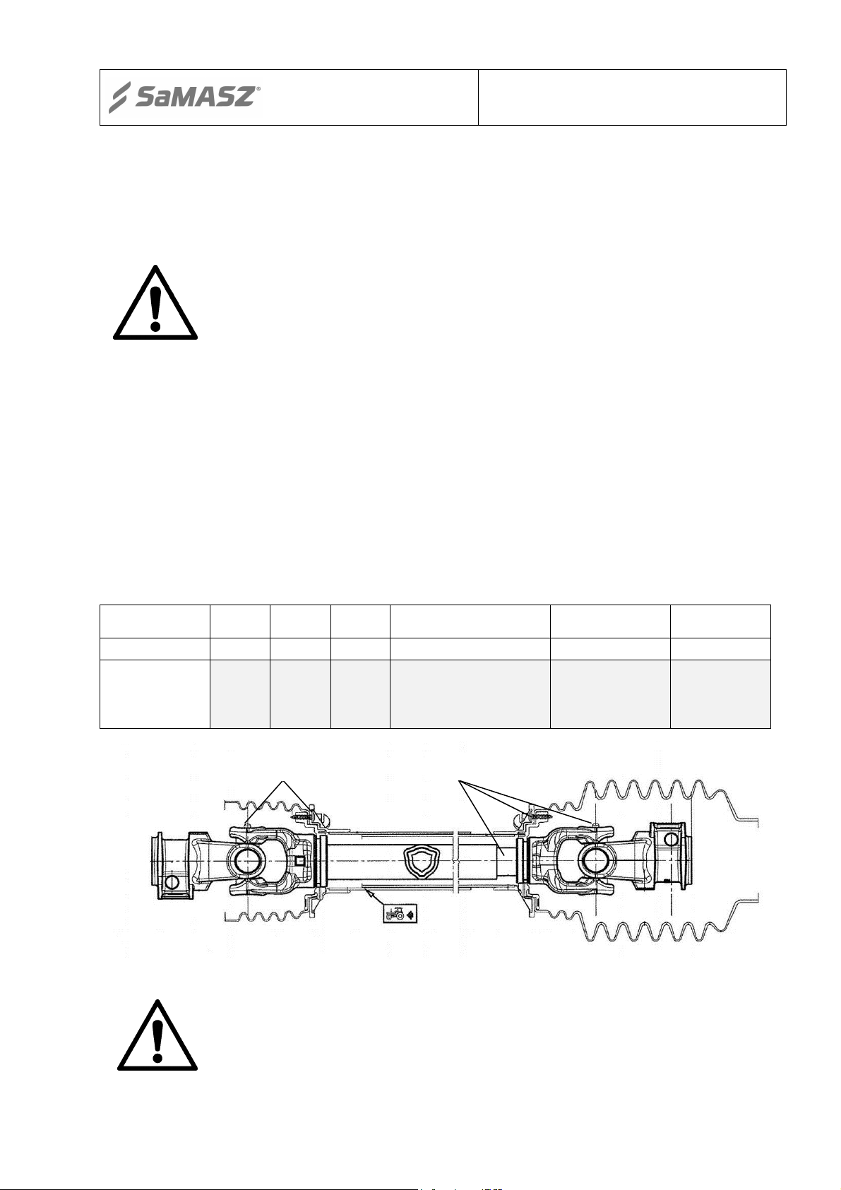
When near telescopic articulated shaft pay attention to guards in transport and working
position due to existing potential risk of damaging the guards with tractor’s parts.
Use telescopic articulated shaft holding CE marking with guards in good condition.
Pay attention that telescopic articulated shaft guard is always on and secured with chains
against rotation.
It is inadmissible to use telescopic articulated shaft with no full guards on from tractor’s PTO
and machine's PTO shafts’ side.
Mounting and dismounting of telescopic articulated shaft can only take place with
transmitter’s shaft, PTO shaft and engine all turned off and ignition key taken out.
Prior to turning off tractor’s transmitter’s shaft make sure, whether the following are true:
chosen number and direction of tractor's transmitter's shaft rears and admissible number and
direction of gritter's rears.
Prior to turning on transmitter’s shaft make sure whether there are no persons or animals
within machine's operating reach.
Be careful when telescopic articulated shaft is rotating. Danger of hand catching or crushing.
Turn off the transmitter’s shaft, whenever any obstacle is on the way or its operation is not
necessary.
Put the dismounted telescopic articulated shaft away onto intended support.
Once the telescopic articulated shaft is dismounted put a cap onto the transmitter’s shaft end.
Using damaged telescopic articulated shaft is forbidden.
Repair and maintenance works as well as other works related to removing functional defects
should be conducted with both drive and engine off and ignition key taken out.
Examine nuts and bolts on regular basis and if need be tighten.
When replacing parts, use only adequate tools and protective gloves.
Spare parts must comply with technical requirements provided by the manufacturer.
Hydraulic hoses should be inspected on regular basis and if any damage is found or they
expire, replace these with new ones. Expiry period for hydraulic hoses should be no longer
than 5 years,
Never use scotch tape to repair damaged hydraulic hoses,
When connecting hydraulic hoses to tractor hydraulic connectors make sure, that either
tractor’s or gritter’s hydraulics are pressure free,
When servicing hydraulic assembly, always wear protective gloves and eyewear. Hydraulic
oil leaking under pressure (16 MPa) may permeate through the skin and cause its infection
thereafter. If such is experienced, visit a doctor immediately,
NOTE:
1. Comply with the abovementioned provision to prevent an
accident and avoid life and health hazard.
2. Operating the machine by persons, who are unauthorized,
unskilled, ill, drunk or under influence of drugs, and children in
particular is forbidden.

User's manual
Tractor gritter
SAND 400 (H); SAND 600 (H)
- 8 -
4.1. Safety rules when driving on public roads
Due to road traffic safety and respective provisions, it is necessary, that when operating or
driving on public roads the aggregate consisting of tractor and mounted gritter meets requirements
as these for the tractor itself. Machine, which is mounted and projects tractor's rear outline for more
than 1 m, poses hazard to other vehicles, so it must be equipped with corresponding marking.
Tractor gritter SAND – mounted on tractor’s rear projects tractor’s rear outline for 1.47 m.
Fig. 5
.
Movable lighting fixture for gritter,
where: 1 – unified lamp, 2 – reflective
light, 3 – warning plates, 4 – cable
connectors, 5 – connecting cable, 6 –
cable for connecting with tractor’s
electrics.
Fig. 6
.
Placement of movable lighting
fixtures and marking plate on gritter.
1 – triangle marking plate, 2 –
movable lighting fixture.
When driving on public roads, the following must be on at gritter’s rear (Fig. 5, Fig. 6):
additional lights (such as: tractor's rear lights);
white and red warning plates;
warning triangle to mark a slow-moving vehicle.
The abovementioned lighting devices and marking plate can be ordered at points trading
farming machinery parts or at the manufacturer.
Movable lighting fixture for gritter consists of:
unified lamps (such as in tractor);
rear round reflective lights;
warning plates;
warning triangle.
Gritter’s design allows for mounting movable lighting fixtures and warning plates and
marking plate. Standardized holders at lighting fixtures and marking plate allow for their use in
other mountable machines as: dibbers, pickers, plows.
Lighting fixtures should be mounted in holders, so as to: lamp lights, painted surfaces (or
white and red stripes) of warning plates, surface painted with fluorescent paint of warning triangle
are directed at the aggregation's rear.
Lighting fixtures, warning plates and marking plate are not part of gritter's basic equipment.

User's manual
Tractor gritter
SAND 400 (H); SAND 600 (H)
- 9 -
NOTE:
Pay attention to connecting movable lighting fixtures to tractor’s
electrics. Missing machine’s lighting, warning plates and marking
plate may lead to an accident.
4.2. Residual risk
Residual risk description
Despite the fact, that the manufacturer takes responsibility of SAND tractor gritter’s design
and marking in order to eliminate any risk during operation and maintenance, some certain elements
of risk are unavoidable.
Residual risk results from incorrect or improper behavior of the machine’s operator.
Major source of risk follows these forbidden operations:
use the gritter for purposes other than mentioned herein;
operating gritter by minors as well as not being learned with content of the operator's manual or
by persons without qualifications to drive tractors,
operating machine by persons under influence of alcohol or other abusive substances;
operating telescopic articulated shaft without or damaged guards;
getting limbs nearby telescopic articulated shaft in motion;
entering machine when operating or standstill;
remaining between gritter and tractor with engine in motion;
remaining of unauthorized persons within close distance when operating;
taking out safety guards with engine in motion;
performing operations related to machine's servicing and adjustment with engine on;
leaving machine when operating alone.
When describing residual risk, gritter SAND shall be considered a machine, which until the
moment of production launching had been designed and manufactured in accordance with top
technology level actual as per the gritter’s manufacture date.
Residual risk assessment
Keep the following recommendations:
learn operator’s manual thoroughly,
do not allow any person to remain on the machine when operating and driving,
do not remain between machine and tractor with engine in motion,
do not put limbs in places of potential risk,
adjust gritter only with tractor’s drive off and ignition key taken out,
do not perform any self-modifications and repairs,
do not perform gritting, if any unauthorized persons are within less than 6 m,
maintenance and repair of the machine shall be performed by skilled personnel only,
the machine shall be operated by persons who hold adequate qualifications to drive tractors and
have learned the operator’s manual,
protect the machine from children, as it is possible to eliminate residual risk when operating the
gritter with no hazard to people and the environment.

User's manual
Tractor gritter
SAND 400 (H); SAND 600 (H)
- 10 -
NOTE:
There is possibility of residual risk if not complying with specified
recommendations and advices.
4.3. Transport
Tractor gritter should be transported on any transport means in fully compacted position
(either mounted on tractor or resting at trailer).
The machine should be transported in horizontal position on a transport pallet or directly on
the floor of loading box of a transport means and secured against shifting (owing to gritter’s linkage
legs, which are used for mounting to a wooden pallet or floor be means of nails or bolts; protective
belt can also be used).
Charging gritter should be performed by means a lifting device while keeping particular
caution and paying attention, so as the gritter is not exposed to any damage.
Gritter is delivered by the manufacturer in accordance with the following:
tractor gritter (pcs.) 1
operator's manual with catalogue of spare parts (pcs.) 1
warranty card (pcs.) 1
declaration of conformity EC (pcs.) 1
spray paint (150 ml)
Fig. 7. Loading onto transport means

User's manual
Tractor gritter
SAND 400 (H); SAND 600 (H)
- 11 -
4.4. Warning decals
No.
Warning symbol
Meaning
Placement on
machine
1
Prior to any operations learn
the content herein.
Frame
(Upper left beam)
2
Prior to approaching any
maintenance or repair works,
turn the feeding off and take
ignition key out.
Frame
(Upper left beam)
3
Connection
between machine and tractor
with telescopic articulated
shaft.
Frame
(Upper right
beam)
4
Pulling in of body – drive
transmission assembly.
Do not take off safety guards
with engine in motion;
Frame
(Upper right
beam)
5
Support point of truck’s fork
Frame
6
Pulling-in of upper limb –
belt gear.
Do not take off guards with
machine in motion.
Belt guard
7
Do not touch machine parts
until all
of its assemblies are stopped.
Disk guard
8
Keep safe distance. Danger
of bodily injury
Disk guard
NOTE:
a) all warning decals (labels) should be clean and legible,
b) lost or damaged decals (labels) must be replaced with new ones,
c) new decals (labels) may be ordered at the manufacturer,

User's manual
Tractor gritter
SAND 400 (H); SAND 600 (H)
- 12 -
5. SERVICING AND OPERATING
Prior to operation commencement:
lubricate all lubrication points with a solid grease;
check oil level in 3-point linkage gearbox and refill if need be;
examine torque of all bolts and nuts;
examine tensioning of spreading disk driving v-belt,
examine tensioning of spreading disk driving transmission belt,
examine tensioning of transmission belt,
mount gritter on3-point linkage frame,
If gritter was idle for a longer period, prior to commencing operation:
1. provide general inspection:
- thoroughly clean all surfaces of lubricating nipples and threads to be lubricated;
- lubricate all points with use of a grease gun;
- push-in the grease until fresh grease appears on inner side of cooperating parts;
- examine mounting of spreading disk;
- examine tensioning of v-belts and provide general inspection of pulleys;
- examine even tensioning of transmission belt;
- examine oil level in the gear box;
- trial turn gritter’s PTO shaft;
2. trial commission gritter i.e.:
- mount on tractor;
- turn tractor’s PTO shaft drive on and at minimal engine rpm transmit drive onto the machine
by short and gentle clutch turn on;
- if operation is proper – (evenly, without intervals and loudness) increase engine rpm up to 540
rpm;
3. once the abovementioned actions are taken, gritting may be approached.
Gritter’s working height, i.e. spreading disk above the ground should be approx. 800 mm.
NOTE:
Observe manufacturer’s recommendations and provisions to provide
defect-free operation and extended service life.
5.1. Charging gritter's container
Due to the fact, that height of manual charging of gritter considered a vertical distance
between the top edge of the container and the ground is more than 1,000 mm, use other means,
which is suitable for this kind of work e.g.: trailer, ramp, loader.
NOTE:
Do not allow for charging sand or salt in quantity greater than
provided by manufacturer for the particular machine type.
NOTE:
When charging, the gritter must be lowered onto the ground. Be
extremely careful when charging the gritter.

User's manual
Tractor gritter
SAND 400 (H); SAND 600 (H)
- 13 -
NOTE:
Charging with material in excess may lead to damaging the machine
or cause a work place accident. It is inadmissible to mechanically
charge the gritter by means of a loader, if any unauthorized personnel
is nearby.
NOTE:
Materials (fine sand, gravel, sand) used for gritting must be dry,
stored under roof and protected against weather conditions. Natural
aggregates should be as uniform as possible.
5.2. Operation
When gritting, control on regular basis whether spreading rate is proper.
In order to aggregate machine on, use tractors featuring front axis weights. Do not overload
the container, and adjust its amount depending on the tractor, on which the gritter is mounted. In
order to keep the tractor's control proper, pressure of its front axis (with mounted gritter on and
fully charged with sand or salt and lifted up to working position) must be at least 20 % of tractor’s
weight itself.
In order to start the gritter:
prepare the gritter for operation (see section 5);
charge the container with sand or salt;
start the tractor;
turn PTO shaft on;
engage the proper gear, so as to keep working speed according to working conditions;
slowly release the tractor’s clutch;
- during the first drive check whether gritting is even and symmetric.
6. OPERATING SERVICE
Gritting servicing is based on proper usage and keeping the machine clean. Transport
drives (to work place) shall be taken with empty container and with telescopic articulated shaft
dismounted from tractor’s PTO shaft.
NOTE:
During each interval in gritter’s operation, turn the gritter’s drive off,
take ignition key out and lower the machine onto the ground.
NOTE!
Do not transport any loads or persons on the machine!
Once an operation is completed, clean the container and sweep out any remaining sand or
salt. Next wash and dry. Leave the dismounted gritter on an even and paved surface.

User's manual
Tractor gritter
SAND 400 (H); SAND 600 (H)
- 14 -
A
b)
N
6.1. Inspections
During the machine’s operating period, inspect:
Tensioning and position of transmission belt;
tensioning of v-belt (every 100 hours of work);
tensioning of v-belts of transmission belt’s drive (every 100 hours of work);
oil level in the gearbox (replace every 200 hours of work – see LUBRICATING)
6.2. Tensioning and position of transmission belt
- using tensioning bolts (N, Fig. 8) adjust belt tensioning whenever skid occurs on the tensioning
drum;
- after 15 minutes of the idle work, the belt should be located in central position on rollers. If tape
starts to come off from the drum, increase the belt’s tensioning with a bolt from the side, to
which the belt is moved,
- belt’s tensioning range can be adjusted within 100 – 140 mm. When the belt is properly tensed,
dimension A(Fig. 8b) is 122 mm.
Fig. 8. Proper position of transmission belt
6.3. Tensioning of v-belt
- loosen two M10 bolts, which mount the disk’s base;
- adjust the belt’s tensioning with use of M12 bolt;
- tighten both bolts, which mount the disk’s base.
6.4. Tensioning of v-belts
- adjust the tensioner’s support.
6.5. Adjusting clearance over transmission belt
Valve position is set on basis of digital scale (Fig. 9). Clearance between the valve (upon its
closure) and the belt should be more than 5 mm,
Prior to commissioning of SAND gritter adjust clearance over transmission belt with use of
board L(Fig. 10). Clearance between board Land the belt should be 25 mm.
a)
N
N

User's manual
Tractor gritter
SAND 400 (H); SAND 600 (H)
- 15 -
NOTE:
Prior to starting the gritter, clean the clearance from any remaining ice
and iced sand.
Fig. 9. Adjusting valve position Fig. 10. Clearance between board and transmission
belt
7. DEFECTS AND THEIR REPAIR
Symptoms of improper
operation
Reasons of defect
Solution
Stream of spread sand or
salt
is not continuous
Outlet is clogged
with agglomerated sand or salt.
Remove contamination
Suspension of too damp material. Move the suspended
fertiliser in container.
Transmission belt
slips off the drum
Improper belt tensioning
Increase belt tensioning
by means of tensioning belt
towards the side of shifting
Belt skidding
on driving drum
Too low belt tensioning
Increase belt tensioning with
tensioner’s support
Driving drum
is not rotating
V-belt slipped off
Put on and tension belt
Torn v-belt
Replace belt
Spreading disk
is not rotating
Too low belt tensioning
Tension belt by means of
corresponding bolt
Noisy
gear box
Oil level too low or no oil
Refill oil
Damaged cog gear
Repair gear box
L

User's manual
Tractor gritter
SAND 400 (H); SAND 600 (H)
- 16 -
NOTE:
Prior service works turn tractor’s drive off and take ignition key
out.
NOTE:
Do not remove clogs or poke the material when spreader is
operating.
8. STORING AND MAINTENANCE
After working season:
clean and wash gritter thoroughly;
examine paintwork and if need be clean out of rust and dirt, degrease and cover with primer,
and when dry, cover with surface paint;
repair or replace damaged or worn parts;
clean and put solid grease on threads of tensioning bolts for transmission belt and threads of
valve and discharger bolts.
lubricate all other yellow-marked points in accordance with lubrication schedule;
release tensioning of transmission belt and tensioning of v-belts;
assembled and serviced gritter is recommended to be stored in dry place and on even surface
with empty container, in manner which will not to cause any injury to people and animals.
NOTE:
1.
Prior to each use of the gritter grease support bearing at the
gear box and drum bearings. Not meting this condition will
cause damage to bearings and gear box.
2. Potential oil leak is a hazard to natural environment.
8.1. Lubricating
Thorough lubricating and application of adequate greases shall provide machine’s proper
operation and protects cooperating parts against excess exploitation.
Lubrication points provided with lubricating nipples are filled with lubricant by means of a
grease gun.
Prior to lubricating, clean each lubricating nipple.
Lubricate according to lubrication schedule.

User's manual
Tractor gritter
SAND 400 (H); SAND 600 (H)
- 17 -
LUBRICATION SCHEDULE
No.
Name No. of
lubricating
points Grease or oil class Lubrication
every (hours)
1. Gear box 1 gearbox oil PZ 200
2. Bearings in drums 4 SM-1 8
3. Support bearings 1 SM-1 8
4. Belt tensioner 1 SM-1 8
8.2. Examining oil level in gear box
Examine whether there are no leaks from the gear box, if so then tighten bolts of valves.
Unscrew bolt M6 – item 41 on cat. fig. 1a (oil level gauge), on gear box body and if there is
no oil sipping out of the hole, refill until oil appears in hole M6. Re-tighten bolt M6 in hole found in
the body and protect with silicone.
In case of oil replacement:
drain the whole oil, twisting lower plug off – item 25 on cat. fig. 1a;
twist on the lower plug again;
twist the upper plug off – item 25 on cat. fig. 1a;
fill with 0.3 l of gearbox oil;
twist the upper plug on.
9. DISMOUNTING AND WITHDRAWAL FROM USE
When dismounting provide segregation of parts taking type of material, from which these
have been made into consideration. Store fluids, metal, rubber and plastic parts separately. Parts,
which cannot be re-used, shall be delivered at:
metal – scrap yard;
plastic – waste disposal place;
rubber – utilization plant;
gearbox oil – recycling plant.
NOTE:
When draining gearbox oil, pay particular attention, so as not to
cause any environment pollution.
Parts gathered as a result of withdrawal from use or dismounting
should be protected from access of children and animals. Protect
these against children and animals in particular
.

User's manual
Tractor gritter
SAND 400 (H); SAND 600 (H)
- 18 -
10. WARRANTY CARD
TRACTOR GRITTER SAND
The product quality has been checked and meets the required standards and regulations and is
permitted for use.
NOTE:
Warranty card without the required information or with corrected or
illegible information –is invalid.
Machine type
Machine name
SAND 400 (H)
Tractor gritter
SAND 600 (H)
Tractor gritter
Serial no.
Date of manufacture
Manufacturer stamp
QC signature
Date of purchase
Dealer stamp
Dealer signature
Other manuals for SAND 400
1
This manual suits for next models
3
Table of contents
Other SaMASZ Tractor Accessories manuals
Popular Tractor Accessories manuals by other brands

Grouser Products
Grouser Products 450 Owner's manual & parts book

AL-KO
AL-KO 161 VB-2 Translation of the original operating instructions

Maschio
Maschio PINOCCHIO 130 Use and maintenance

Raven
Raven SmarTrax installation manual

Avantco
Avantco Mini Digger 150 Operator's manual for Attachment

Avantco
Avantco A35411 Operator's manual for Attachment