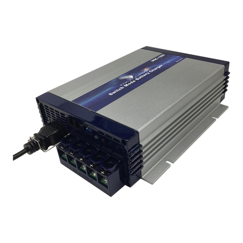
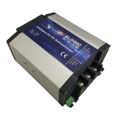
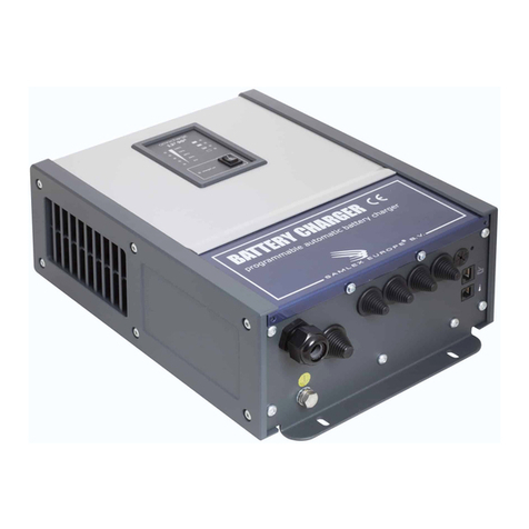
Samlex Europe SEC - 1215E User manual

www.samlex.com
www.samlex-solar.com
SEC - 1215E
SEC - 1230E
SEC - 2415E
Model No.
AUTOMATIC BATTERY CHARGER
OWNER’S MANUAL
Please read this manual before operating your charger

CONTENTS
IMPORTANT SAFETY PRECAUTIONS................................................. 2
DESCRIPTION AND FEATURES .......................................................... 3
CHARGING STAGES................................................................................ 4
PROTECTIONS ......................................................................................... 5
INSTALLATION........................................................................................ 6
CHARGER OPERATION ...............................................................7,8,9,10
TROUBLESHOOTING........................................................................11,12
INTERNAL FUSE RATINGS................................................................. 12
SPECIFICATIONS................................................................................... 13
WARRANTY............................................................................................ 14

IMPORTANT SAFETY PRECAUTIONS
Hazardous conditions may result if the charger is not installed or operated correctly.
Please read the following instructions to prevent personali njury or damage to the charger:
BatteryRelated
r To reduce the risk of battery explosion, follow these instructions and those marked
on the battery
r Never smoke or allow an open spark or ame in the vicinity of the battery or engine
r Charge only Lead Acid type of batteries (AGM/Wet/Gel/Fleece).
Do not charge other type of batteries like Nickel Cadmium( NiCad) ,
Nickel-MetalHydride(Ni-MH),Dry-Celletc. Other types of batteries might burst causing
personal injury
r Never charge a frozen battery
rWorking in the vicinity of Lead Acid batteries is dangerous. Batteries generate
explosive gases during normal operation. Take necessary safety precautions when
installing the charger near a battery or in a battery compartment (Follow safety
instructions given by the battery manufacturer)
r Never place the charger directly above or below the battery being charged; gases or uids
from the battery will corrode and damage the charger. Locate the charger as far away from
the battery as DC cables permit. Do not install in the same compartment as batteries
ChargerRelated
r Do not operate the charger in a closed-in area or restrict ventilation in any way.
Install in a well ventilated, cool, dry place.
r The charger must not be operated in a damp or wet environment. When mounting in a
boat, make sure it is not subjected to bilge watersplash.
r Do not block the ventilation openings/openings for the coolingfan. There should be at
least 15 cm. clearance all around the unit.
r Installation and wiring must comply with the local and the national electrical codes.
It is recommended that installation and wiring may be done by a certied electrician
r Wrong installation on a boat may lead to corrosion of the boat. It is recommended that
installation on the boat must be carried out by a boat electrician.
r Disconnect the AC input power to the charger before connecting/disconnecting the batteries
or other DC loads or when working on the charger.
r Disconnect the AC input power before changing setting of the Dip Switch.
r The chassis of the charger is connected to the earth ground pin of the power cord plug.
Ensure that the earth ground pin of AC receptacle feeding the charger is connected to
earth ground
r Do not use an adapter. If a grounding type of receptacle is not available, do not use this
charger until the proper outlet is installed by aqualied electrician.
Do not operate the charger if the power cordis damaged
2

DESCRIPTION
These chargers are used to charge Lead Acid Batteries (Fle ece/AGM/Gel/Wet). SEC-1215E
(Maximum charging current 15A) and SEC-1230E ( Maximum charging current 30A) are used
to charge 12Vbatteries. SEC-2415E (Maximum charging current 15A) is used to charge
24V batteries. These chargers can be powered from AC power source of 230 V, 50Hz.
FEATURES
r State of the art switched mode technology is used for very high efciency, light weight and
quiet operation.
r User selectable 2 or 3 stage charging algorithm ensures rapid and safe charging of all types
of lead acid batteries-Fleece, AGM, Wet, Gel or batteries with external load.
(Through externally accessible Dip Switch- see pages 7 & 8 for instructions )
r Fully automatic —”Connectand Forge” operation
r 3banksofbatteriescanbecharged simultaneously without use of an external battery isolator
r Monitoring through ON status LED and Amp meter
r Temperature controlled cooling fan (SEC-1230E, SEC-2415E)
r Protectionsagainst short circuit, overcurrent, reverse battery connection and over
temperature (over temperature for SEC-1230E and SEC-2415E)
r Can be used as a power supply or as a DC UPS ( Uninterruptible DC Power Supply )
when used with a battery (Dip Switch set at—Battery with load“)
COOLING
SEC-1215E is cooled by convection and does not have any thermal overload shut down.
SEC-1230E and SEC-2415E are cooled by convection and in addition, have a temperature
controlled fan for forced air cooling. Two temperature sensors mounted on the power
transformer control the switching of the fan and over temperature shut down. The fan will be
switched on by the rst temperature sensor when the power transformer reaches 70 degrees C.
HENCE,AT LOWER LOADS, THE FAN MAY NOT CUT IN AND WILL BE OFF.
THIS IS NORMAL. In case the fan fails or if the cooling is not adequate, the second
temperature sensor will shut down the unit ifthe power transformer reaches 100 degrees C.
The red LED will switch off. The unit will automatically recover on removal of thermal
overload condition.
3

CHARGING STAGES
NOTE ! - VOLTAGE READINGS ON NO LOAD
The output has one common negative terminal and three positive terminals for charging 3
banks of batteries. Each positive terminal has an internal isolating diode in series which has a
forward voltage drop of 0.8 to1.1V. On no load (that is when no battery or other dc load is
connected to any of the 3 terminals), the voltage reading will read 0.8to1.1V higher than the
specied oat voltage. Note that thes pecied oat voltage is at a load of1A. Also, the voltage
on the terminals not connected to the load (forexample,whenone bank of battery is connected
to one positive terminal, the other 2 positive terminals will remain disconnected) will read
0.8to1.1Volt higher than the voltage of the loaded terminal.
These chargers can be manually selected to operate in 3 stage or 2 stage modes (Please see
“Selecting the Type of Battery and Charging Stages“ at page 7 ). The charging stages are
described below :
STAGE 1 -CONSTANT CURRENT OR BULK CHARGE STAGE
When the battery is low, it will try to draw larger charging current. The charger senses the
current draw and limits this to the maximum permissible value (15A for SEC-1215E/
SEC-2415E and 30A for SEC-1230E). Bulk charging takes place at this constant current.
In this condition of constant current, the voltage measured at the charger or battery terminals
will be the battery ‘s own voltage. The constant current injected into the battery starts restoring
the battery capacity and it‘svoltage starts rising. When this voltage approaches the threshold
of battery “gassing“, termed “boost or absorption voltage“, the charger automatically switches
over to Stage 2 -”Boost or Absorption Stage“. The value of this voltage depends upon the type
of battery being charged (See Dip Switch Settings). By this time, approximately 80% of the
battery capacity will normally have been restored (Note: The percentage capacity restored till
the point the battery reaches the boost or absorption voltage is inversely proportional to the
value of the bulk charge current.)
STAGE 2 -CONSTANT VOLTAGE BOOST OR ABSORPTION STAGE
As explained above, whenthebatteryvoltageapproaches the pointwhere battery ”gassing“ can
begin, the charger automatically switches over to the ”Boost or Absorption Stage“. The charger
applies a constant voltage whose value depends upon the type of battery selected
(See Dip Switch Settings). This controlled overcharge restores the balance 20% of the capacity
in a minimum amount of time. As the capacity is fully restored, the charging current starts
reducing. When the current reduces below the preset threshold, the charger automatically
switches to the “Float or Maintenance Stage“.
STAGE 3 -CONSTANT VOLTAGE, FLOAT OR MAINTENANCE CHARGING STAGE
As explained above, as the charging current drops below the preset threshold ( 1.5 to 2 amps for
SEC-1215E / SEC-2415E and 2.5A to 3A for SEC-1230E ), it signals that the battery is 100%
charged. In this “Float or Maintenance Charging Stage“, the charger outputs a constant voltage
of 13.8V for 12V system and 27.6V for 24V system. This helps in maintaining 100% capacity of
the battery and also compensates for self discharge. The battery can remain connected in this
stage in denitely without the risk of overcharging or excessive loss of electrolyte.
4
This manual suits for next models
2
Table of contents
Other Samlex Europe Batteries Charger manuals

Samlex Europe
Samlex Europe PSC1600-12-60 User manual

Samlex Europe
Samlex Europe Omnicharge OC48-40 User manual

Samlex Europe
Samlex Europe Omnicharge OC12-90 User manual

Samlex Europe
Samlex Europe WSC-1250Li User manual

Samlex Europe
Samlex Europe WSC-1215 User manual

Samlex Europe
Samlex Europe WSC-1250 User manual

Samlex Europe
Samlex Europe ELOGIC User manual

Samlex Europe
Samlex Europe WSC-1230 User manual