BESCHREIBUNG
Der Battery Guard Waterproof BGW100/200
(nachstehend „BGW“ genannt) ist ein intelligenter,
benutzerprogrammierbarer, komplett Batteriewächter.
Der BGW hat Erweiterungsmöglichkeiten wie einen
Aus-Schalter und einen Alarm-Ausgang, an den
ein Summer, eine LED-Leiste oder ein Relais
angeschlossen werden kann. Um geringe Verluste
zu gewährleisten, ist das BGW mit zwei
Anschlussbolzen ausgestattet: Eingang+ und
Ausgang+. Die übrigen Anschlüsse (Minus-, Remote
Off-, Cong-Eingang und Status/Alarm-Ausgang)
werden über 6,3 mm Faston stecker angeschlossen.
Der BGW ist außerdem mit einer gut ablesbaren
LED-Zustandsanzeige ausgestattet, woran der
Benutzer den Betriebszustand des BGW ablesen
kann. Außerdem ist der BGW mit einer „automatischen
Platinensystem-Erkennung“ ausgestattet, sodass
der BGW automatisch erkennt, ob er an ein 12 V-
oder 24 V-System angeschlossen ist.
INSTALLATION
Der BGW sollte auf einer kühlenden Unterlage (aus
Metall) montiert werden, damit die entstehende
Wärme abgeleitet werden kann.
Verwenden Sie eine maximale Kabellänge von
50 cm zwischen der Batterie und dem BGW, um
eine genaue Überwachung der Batteriespannung
zu gewährleisten.
Achtung!
• Das Produkt darf nur von fachkundigen
Installateuren/Monteuren angeschlossen werden,
die mit den Vorschriften für die Arbeit mit hohen
Akkuspannungen vertraut sind.
• Bei Nutzung von schlechten Anschlussmaterialien
und/oder zu dünnen kabel kann der BGW
beschädigt werden.
• Ein Kurzschluss zwischen dem Plus- und
Minusanschluss des Akkus kann Ihr System
beschädigen.
• Immer Sicherungen (mit dem richtigen
Nennstromwert) verwenden.
• Verwenden Sie für den negativen (–) Anschluss
ein 1,5 mm2Kabel mit 1A Sicherung für das
BGW100 und 5A Sicherung für das BGW200 von
der Batterie (-) zum BGW. Diesen Anschluss nur
für die BGW verwenden!
SCHALTPLAN (SIEHE LETZTE SEITE)
FUNKTIONSWEISE
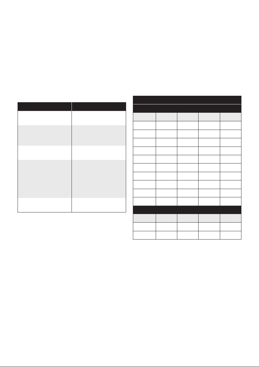
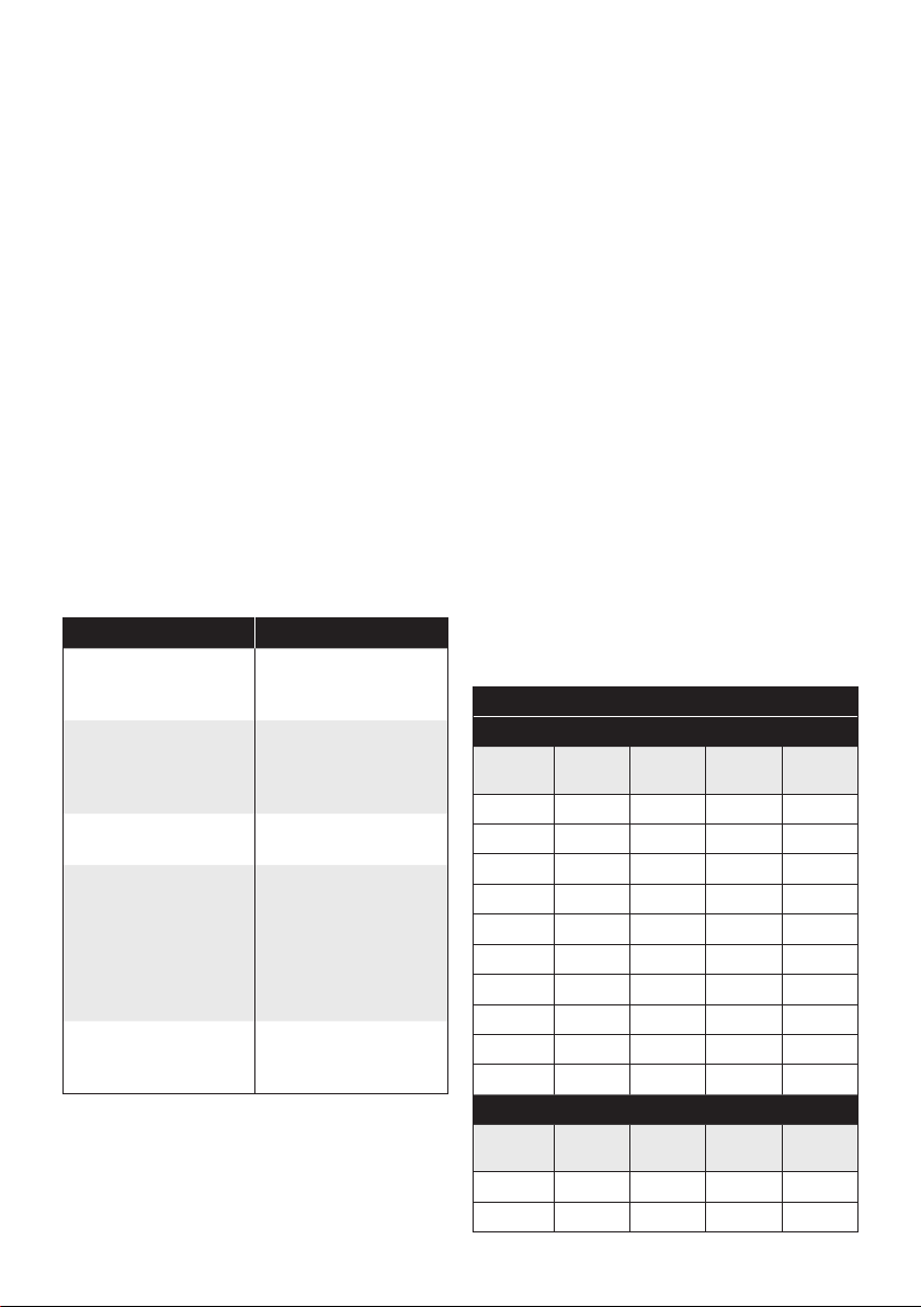
Betriebsspannungsschutz
Die Werte für den Betriebsspannungsschutz –
Schwellwert für die Unterspannung, Wiedereinschal-
tung nach Unterspannung, Schwellwert für die
Überspannung und Wiedereinschaltung nach
Überspannung – können vom Benutzer eingestellt
werden. Wie das geht, wird im Kapitel „Kongurieren/
Programmierung“ beschrieben.
Unterspannung
Wenn die Betriebsspannung des BGW 15 Sekunden
lang den Grenzwert für die Unterspannung
unterschreitet, wird der Status/Alarm-Ausgang
aktiviert. Die LED zeigt auch Unterspannung an.
Nach einer Minute schaltet sich der BGW ab.
Auch der Alarm-Ausgang und die LED schalten
sich ab. Sobald die Betriebsspannung des BGW
5 Sekunden lang über dem Reset-Wert liegt, schaltet
sich der BGW wieder ein. Die LED zeigt nun auch
wieder an, dass der BGW eingeschaltet ist.
Überspannung
Der BGW schaltet sich aus, falls die Betriebsspannung
des BGW 0,5 Sekunden über dem Schwellwertfür
die Überspannung liegt. Außerdem zeigt der Status/
Alarm-Ausgang (mit einer Frequenz von 1 Hz) an,
dass eine Überspannung erkannt wurde. Diese
Informationen werden auch über die LED angezeigt.
Überstromschutz
Der durch den BGW ießende Strom wird ständig
gemessen. Wenn zu lange ein zu hoher Strom
durch den BGW ießt, schaltet sich der BGW ab, um
Schäden am BGW und dem angeschlossenen Gerät
zu vermeiden. Nach 1 Minute schaltet sich der BGW
wieder ein.
Temperaturschutz
Wenn die Temperatur des BGW über 85 °C ansteigt,
schaltet sich der BGW sofort aus. Die LED zeigt dann
an, dass ein „Problem“ vorliegt. Nach 1 Minute schaltet
sich der BGW wieder ein, wenn die Temperatur unter
75 °C gesunken ist.
GEBRAUCHSANWEISUNG DE