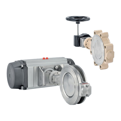
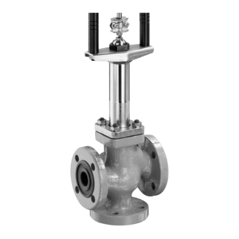
Samson 3310/AT Service manual
Other Samson Control Unit manuals

Samson
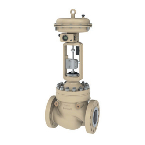
Samson 3249 Service manual
Samson
Samson 3251-E Service manual

Samson
Samson 327 User manual

Samson
Samson 3244-1 Service manual
Samson
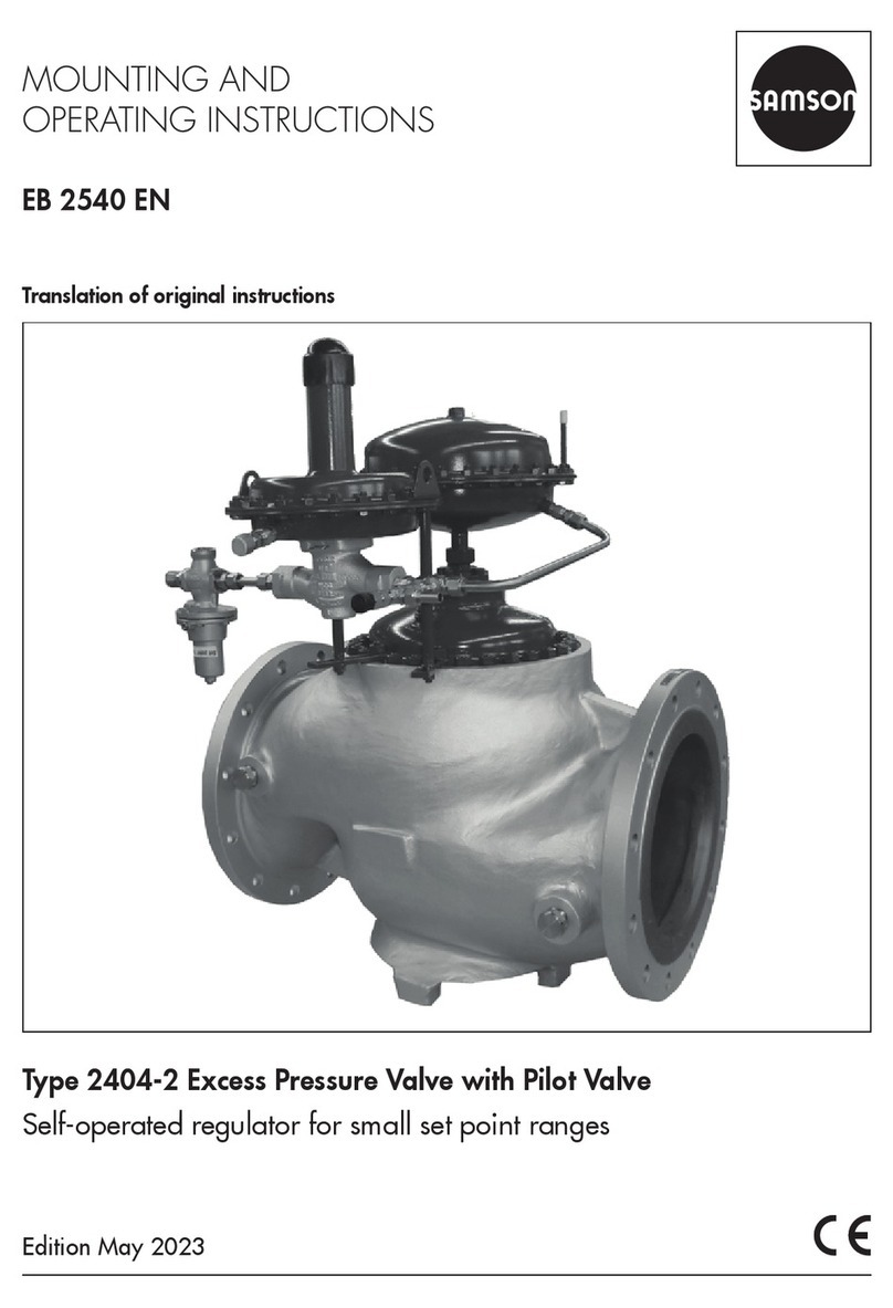
Samson 2404-2 Service manual
Samson
Samson EB 8139 EN Service manual

Samson
Samson 41-73 Series Service manual
Samson
Samson EB 20b Service manual
Samson
Samson 3222/5857 series Service manual
Samson
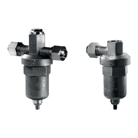
Samson Pfeiffer BR Series User manual
Samson
Samson 2357-1 Service manual
Samson
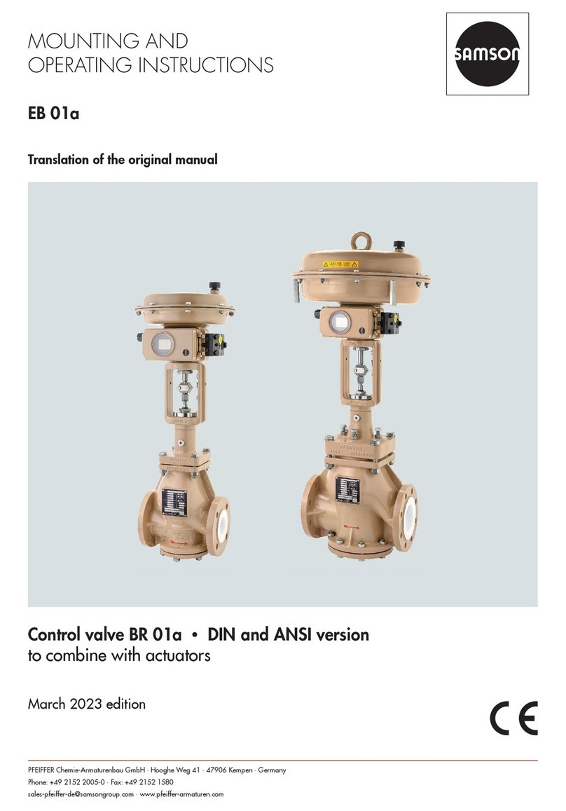
Samson EB 01a Service manual
Samson
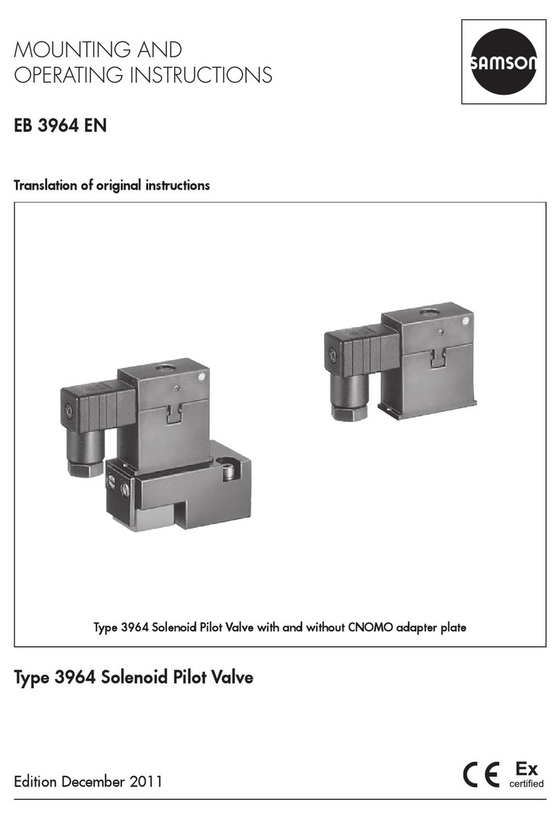
Samson 3964 Service manual

Samson
Samson 3323 Service manual

Samson
Samson 3241 Service manual

Samson
Samson 2405 Series Service manual

Samson
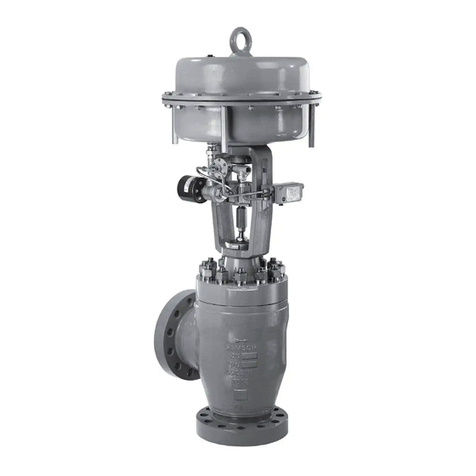
Samson 3251 Service manual
Samson
Samson 3256 Service manual
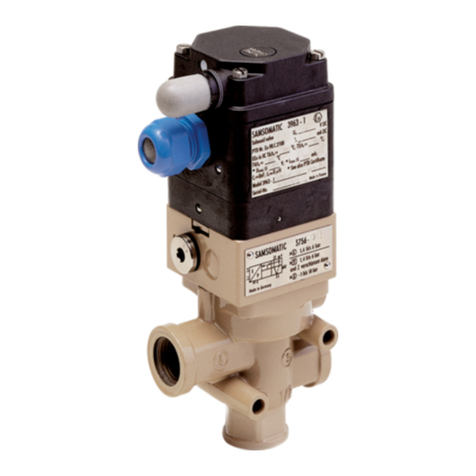
Samson
Samson 3963 Series Service manual

Samson
Samson 3241-1-Gas Service manual
Popular Control Unit manuals by other brands

Festo
Festo Compact Performance CP-FB6-E Brief description

Elo TouchSystems
Elo TouchSystems DMS-SA19P-EXTME Quick installation guide

JS Automation
JS Automation MPC3034A user manual

JAUDT
JAUDT SW GII 6406 Series Translation of the original operating instructions

Spektrum
Spektrum Air Module System manual

BOC Edwards
BOC Edwards Q Series instruction manual

KHADAS
KHADAS BT Magic quick start

Etherma
Etherma eNEXHO-IL Assembly and operating instructions

PMFoundations
PMFoundations Attenuverter Assembly guide

GEA
GEA VARIVENT Operating instruction

Walther Systemtechnik
Walther Systemtechnik VMS-05 Assembly instructions

Altronix
Altronix LINQ8PD Installation and programming manual

