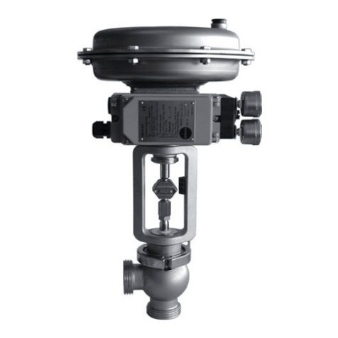
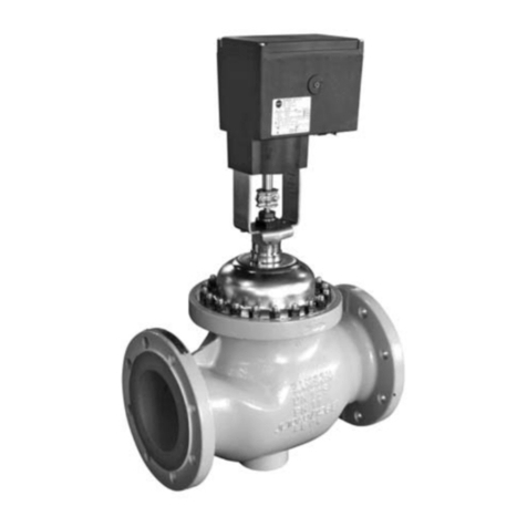
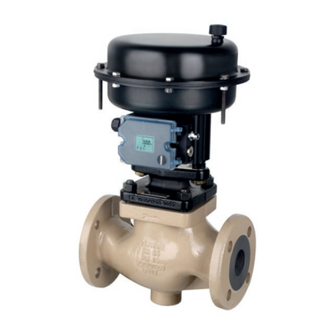
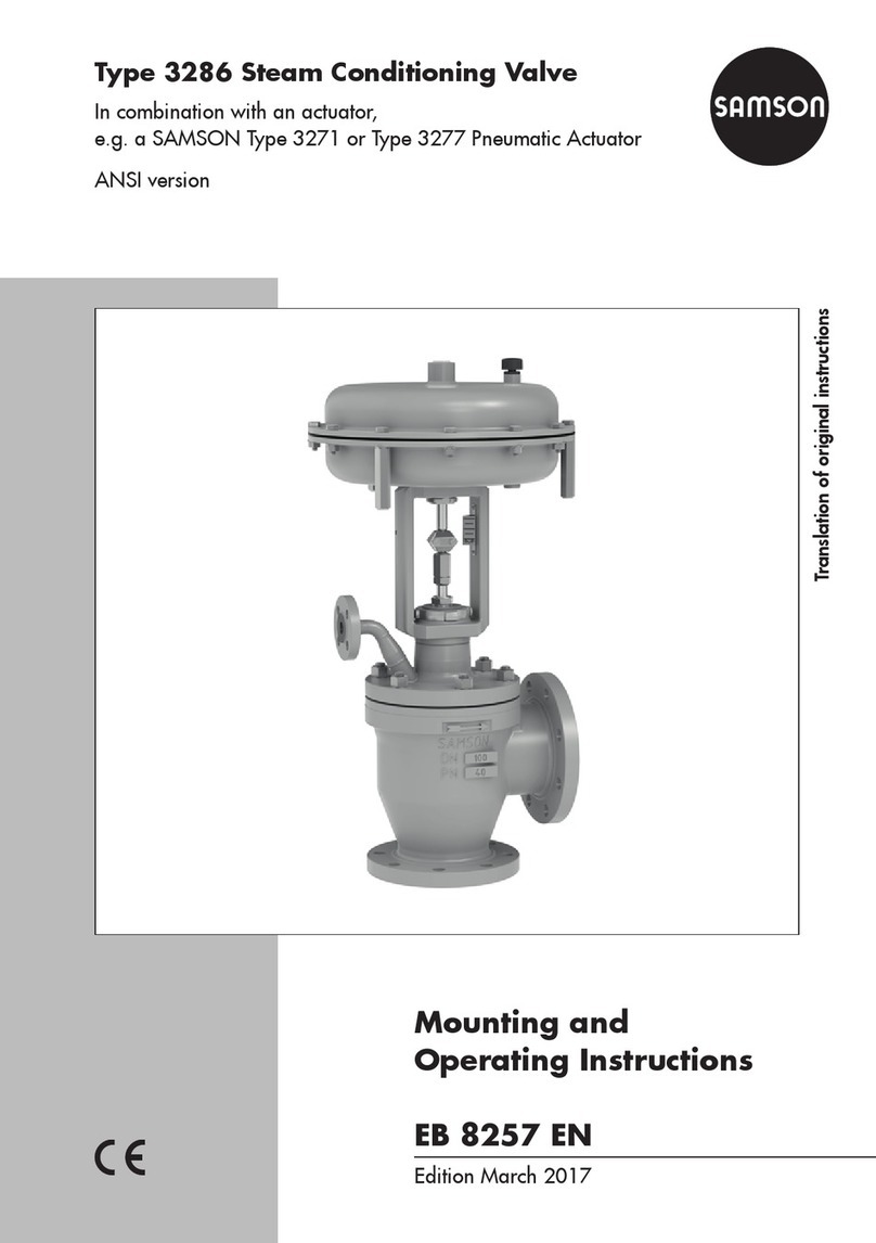
Samson 42-10 Service manual

Translation of original instructions
EB 3009 EN
Type42-10RS Check Valve (backow protection)
Self-operated Regulators
Edition December 2020

Note on these mounting and operating instructions
These mounting and operating instructions assist you in mounting and operating the device
safely. The instructions are binding for handling SAMSON devices. The images shown in
these instructions are for illustration purposes only. The actual product may vary.
ÎFor the safe and proper use of these instructions, read them carefully and keep them for
later reference.
ÎIf you have any questions about these instructions, contact SAMSON‘s After-sales Service
(aftersalesservice@samsongroup.com).
Documents relating to the device, such as the mounting and operating
instructions, are available on our website at www.samsongroup.com >
Service & Support > Downloads > Documentation.
Definition of signal words
Hazardous situations which, if not avoided,
will result in death or serious injury
Hazardous situations which, if not avoided,
could result in death or serious injury
Property damage message or malfunction
Additional information
Recommended action
DANGER
!
WARNING
!
NOTICE
!
Note
Tip
EB 3009 EN

Contents
EB 3009 EN
1 Safety instructions and measures ................................................................1-1
1.1 Notes on possible severe personal injury ......................................................1-4
1.2 Notes on possible personal injury ................................................................1-5
1.3 Notes on possible property damage.............................................................1-7
2 Markings on the device ..............................................................................2-1
2.1 Valve nameplate .........................................................................................2-1
2.2 Actuator nameplate.....................................................................................2-2
2.3 Location of the nameplates ..........................................................................2-2
2.4 Materialidenticationnumber .....................................................................2-2
2.4.1 Type2421RSValve....................................................................................2-2
2.4.2 Type2420RSActuator ...............................................................................2-2
3 Design and principle of operation ...............................................................3-1
3.1 Additionalttings........................................................................................3-4
3.2 Technical data ............................................................................................3-5
4 Shipment and on-site transport ...................................................................4-1
4.1 Accepting the delivered goods .....................................................................4-1
4.2 Removing the packaging from the regulator ..................................................4-1
4.3 Transporting and lifting the regulator............................................................4-2
4.3.1 Transporting the regulator............................................................................4-2
4.3.2 Lifting the regulator .....................................................................................4-3
4.4 Storing the regulator ...................................................................................4-4
5 Installation.................................................................................................5-1
5.1 Installation conditions..................................................................................5-1
5.2 Preparation for installation...........................................................................5-3
5.3 Installation..................................................................................................5-5
5.3.1 Installing the regulator.................................................................................5-5
5.3.2 Cleaning the pipeline ..................................................................................5-6
5.4 Testing the regulator ....................................................................................5-6
5.4.1 Leak test.....................................................................................................5-7
5.4.2 Pressure test................................................................................................5-7
5.5 Proof testing ...............................................................................................5-7
5.6 Insulation ...................................................................................................5-8
6 Start-up .....................................................................................................6-1
6.1 Start-up and putting the device back into operation .......................................6-2
6.2 Starting up the plant....................................................................................6-2
6.2.1 Regulation of steam.....................................................................................6-2
6.2.2 Regulation of liquids....................................................................................6-2

Contents
EB 3009 EN
7 Operation..................................................................................................7-1
7.1 Set point adjustment....................................................................................7-1
8 Malfunctions ..............................................................................................8-1
8.1 Troubleshooting ..........................................................................................8-1
8.2 Emergency action .......................................................................................8-3
9 Servicing....................................................................................................9-1
9.1 Preparing the valve for service work.............................................................9-4
9.2 Installing the regulator after service work ......................................................9-4
9.3 Service work...............................................................................................9-4
9.3.1 Replacing the actuator.................................................................................9-5
9.3.2 Replacing the seat and plug.........................................................................9-5
9.3.3 Replacing the actuator's operating diaphragm ..............................................9-5
9.4 Ordering spare parts and operating supplies ................................................9-5
10 Decommissioning .....................................................................................10-1
11 Removal ..................................................................................................11-1
11.1 Removing the regulator from the pipeline....................................................11-1
11.2 Removing the actuator from the valve .........................................................11-1
12 Repairs ....................................................................................................12-1
12.1 Returning devices to SAMSON ..................................................................12-1
13 Disposal...................................................................................................13-1
14 Certicates...............................................................................................14-1
15 Annex......................................................................................................15-1
15.1 Tightening torques.....................................................................................15-1
15.2 Lubricant..................................................................................................15-1
15.3 Tools ........................................................................................................15-1
15.4 Spare parts ..............................................................................................15-2
15.5 After-sales service.....................................................................................15-2

EB 3009 EN 1-1
Safety instructions and measures
1 Safety instructions and measures
Intended use
TheType42-10RSCheckValveissuitableforbackowprotectioninnetworkscontaining
water,steam,nitrogenorcompressedairupto220°C.ItconsistsofaType2412RSValve
andaType2420RSActuator.
TheType42-10RSCheckValveismainlyusedinindustrialplants.
Theregulatorisdesignedtooperateunderexactlydenedconditions(e.g.operatingpres-
sure, process medium, temperature). Therefore, operators must ensure that the regulators are
onlyusedinoperatingconditionsthatmeetthespecicationsusedforsizingthedevicesat
the ordering stage. In case operators intend to use the regulators in other applications or
conditionsthanspecied,contactSAMSON.
SAMSON does not assume any liability for damage resulting from the failure to use the de-
vice for its intended purpose or for damage caused by external forces or any other external
factors.
ÎRefertothetechnicaldataandnameplateforlimitsandeldsofapplicationaswellas
possible uses.
Reasonably foreseeable misuse
The regulators are not suitable for the following applications:
− Useoutsidethelimitsdenedduringsizingandbythetechnicaldata
− Useoutsidethelimitsdenedbytheadditionalttingsmountedontheregulator
Furthermore, the following activities do not comply with the intended use:
− Use of non-original spare parts
− Performing service and repair work not described
Qualications of operating personnel
The regulator must be mounted, started up, serviced and repaired by fully trained and
qualiedpersonnelonly;theacceptedindustrycodesandpracticesmustbeobserved.
According to these mounting and operating instructions, trained personnel refers to
individualswhoareabletojudgetheworktheyareassignedtoandrecognizepossible
hazardsduetotheirspecializedtraining,theirknowledgeandexperienceaswellastheir
knowledge of the applicable standards.

1-2 EB 3009 EN
Safety instructions and measures
Personal protective equipment
Werecommendcheckingthehazardsposedbytheprocessmediumbeingused(e.g.
uGESTIS(CLP)hazardoussubstancesdatabase).Dependingontheprocessmediumand/
or the activity, the protective equipment required includes:
− Protectiveclothing,safetyglovesandeyeprotectioninapplicationswithhot,coldand/or
corrosive media
− Wear hearing protection when working near the valve
− Hard hat
− Safety harness when working at height
− Safety footwear, ESD (electrostatic discharge) footwear, if necessary
ÎCheck with the plant operator for details on further protective equipment.
Revisions and other modications
Revisions,conversionsorothermodicationsoftheproductarenotauthorizedbySAMSON.
Theyareperformedattheuser'sownriskandmayleadtosafetyhazards,forexample.Fur-
thermore, the product may no longer meet the requirements for its intended use.
Warning against residual hazards
To avoid personal injury or property damage, plant operators and operating personnel must
preventhazardsthatcouldbecausedintheregulatorbytheprocessmedium,theoperating
pressure or by moving parts by taking appropriate precautions. Plant operators and operat-
ingpersonnelmustobserveallhazardstatements,warningandcautionnotesinthese
mounting and operating instructions.
Hazardsresultingfromthespecialworkingconditionsattheinstallationsiteoftheregulator
mustbeidentiedinariskassessmentandpreventedthroughthecorrespondingsafetyin-
structions drawn up by the operator.
Wealsorecommendcheckingthehazardsposedbytheprocessmediumbeingused(e.g.
uGESTIS(CLP)hazardoussubstancesdatabase).
ÎObservesafetymeasuresforhandlingthedeviceaswellasrepreventionandexplosion
protection measures.

EB 3009 EN 1-3
Safety instructions and measures
Safety features
TheType42-10RSCheckValveisavalvewithasafetyfunction.Whenrelievedofpressure,
the regulator is closed by the force of the set point springs in the actuator.
Responsibilities of the operator
Operators are responsible for proper use and compliance with the safety regulations. Opera-
tors are obliged to provide these mounting and operating instructions as well as the refer-
enced documents to the operating personnel and to instruct them in proper operation. Fur-
thermore, operators must ensure that operating personnel or third parties are not exposed to
any danger.
Operatorsareadditionallyresponsibleforensuringthatthelimitsfortheproductdenedin
the technical data are observed. This also applies to the start-up and shutdown procedures.
Start-up and shutdown procedures fall within the scope of the operator's duties and, as such,
are not part of these mounting and operating instructions. SAMSON is unable to make any
statements about these procedures since the operative details (e.g. differential pressures and
temperatures) vary in each individual case and are only known to the operator.
Responsibilities of operating personnel
Operating personnel must read and understand these mounting and operating instructions as
wellasthereferenceddocumentsandobservethespeciedhazardstatements,warnings
and caution notes. Furthermore, operating personnel must be familiar with the applicable
health, safety and accident prevention regulations and comply with them.
Referenced standards, directives and regulations
The regulators comply with the requirements of the European Pressure Equipment Directive
2014/68/EU.RegulatorswithaCEmarkinghaveanEUdeclarationofconformity,which
includes information about the applied conformity assessment procedure. This EU declaration
ofconformityisincludedinthe'Certicates'section.
AccordingtotheignitionriskassessmentperformedinaccordancewithEN13463-1:2009,
section 5.2, the non-electrical regulators do not have their own potential ignition source even
in the rare incident of an operating fault. As a result, they do not fall within the scope of Di-
rective 2014/34/EU.
ÎForconnectiontotheequipotentialbondingsystem,observetherequirementsspeciedin
section6.4ofEN60079-14(VDE0165-1).

1-4 EB 3009 EN
Safety instructions and measures
Referenced documentation
The following documents apply in addition to these mounting and operating instructions:
− Mounting and operating instructions for
e.g. Type2N/NI Strainer uEB1015
− Data sheets for
e.g. Accessories · Differential pressure and ow regulators uT3095
e.g. Type2N/NI Strainer uT1015
− Mountingandoperatinginstructionsaswellasdatasheetsforadditionalttings
(e.g. shut-off valves, pressure gauges etc.).
1.1 Notes on possible severe personal injury
DANGER
!
Risk of bursting in pressure equipment.
Regulators and pipelines are pressure equipment. Impermissible pressure or improper
opening can lead to regulator components bursting.
ÎObserve the maximum permissible pressure for regulator and plant.
ÎIf necessary, a suitable overpressure protection must be installed on site in the plant
section.
ÎBeforestartinganyworkontheregulator,depressurizeallplantsectionsaffected
as well as the regulator.
ÎDrain the process medium from all the plant sections affected as well as the regula-
tor.
ÎWear personal protective equipment.

EB 3009 EN 1-5
Safety instructions and measures
1.2 Notes on possible personal injury
WARNING
!
Risk of personal injury through incorrect operation, use or installation as a result of
information on the regulator being illegible.
Over time, markings, labels and nameplates on the regulator may become covered
withdirtorbecomeillegibleinsomeotherway.Asaresult,hazardsmaygounno-
ticed and the necessary instructions not followed. There is a risk of personal injury.
ÎKeep all relevant markings and inscriptions on the device in a constantly legible
state.
ÎImmediately renew damaged, missing or incorrect nameplates or labels.
Risk of hearing loss or deafness due to loud noise.
The noise emissions depend on the valve version, plant facilities and process medium.
ÎWear hearing protection when working near the valve.
Risk of personal injury due to pressurized components and process medium being
discharged.
Incorrect opening of pressure equipment or mounting parts may lead to the process
medium escaping to the atmosphere.
ÎDonotloosenthecontrollinewhilethevalveispressurized.
Risk of burn injuries due to hot or cold components and pipelines.
Depending on the process medium, regulator components and pipelines may get very
hot or cold and cause burn injuries.
ÎAllow components and pipelines to cool down or warm up to the ambient tempera-
ture.
ÎWear protective clothing and safety gloves.

1-6 EB 3009 EN
Safety instructions and measures
WARNING
!
Risk of personal injury due to residual process medium in the regulator.
While working on the regulator, residual process medium can escape and, depending
on its properties, may lead to personal injury, e.g. (chemical) burns.
ÎIf possible, drain the process medium from all the plant sections affected and the
regulator.
ÎWear protective clothing, safety gloves and eye protection.
Damage to health relating to the REACH regulation.
If a SAMSON device contains a substance which is listed as being a substance of very
high concern on the candidate list of the REACH regulation, this circumstance is indi-
cated on the SAMSON delivery note.
ÎInformation on safe use of the part affected uwww.samsongroup.com/en/
about-samson/material-compliance/reach-regulation/.

EB 3009 EN 1-7
Safety instructions and measures
1.3 Notes on possible property damage
NOTICE
!
Risk of regulator damage due to incorrectly attached slings.
ÎDo not attach load-bearing slings to the actuator housing.
Risk of regulator damage due to unsuitable medium properties.
Theregulatorisdesignedforaprocessmediumwithdenedproperties.
ÎOnlyusetheprocessmediumspeciedforsizing.
Risk of regulator damage due to contamination (e.g. solid particles) in the pipeline.
The plant operator is responsible for cleaning the pipelines in the plant.
ÎFlush the pipelines before start-up.
Risk of regulator damage due to the use of unsuitable lubricants.
The lubricants to be used depend on the regulator material. Unsuitable lubricants may
corrode and damage surfaces.
ÎOnly use lubricants approved by SAMSON.
When in doubt, consult SAMSON.
Risk of leakage and regulator damage due to excessively high or low tightening
torques.
Observethespeciedtorqueswhentighteningregulatorcomponents.Excessivetight-
ening torques lead to parts wearing out more quickly. Parts that are too loose may
cause leakage.
ÎObservethespeciedtighteningtorques(see'Tighteningtorques'inAnnex).
Risk of regulator damage due to the use of unsuitable tools.
Certain tools are required to work on the regulator.
ÎOnly use tools approved by SAMSON.
When in doubt, consult SAMSON.

1-8 EB 3009 EN
Safety instructions and measures
NOTICE
!
Risk of the process medium being contaminated through the use of unsuitable lubri-
cants and/or contaminated tools and components.
ÎKeep the regulator and the tools used free from solvents and grease.
ÎMake sure that only suitable lubricants are used.
SAMSON's After-sales Service can support you concerning lubricant, tightening torques
and tools approved by SAMSON.
Note

EB 3009 EN 2-1
Markings on the device
2 Markings on the device
Severalnameplatesareafxedtothedevice.Thenameplatesareusedtoidentifythesepa-
rateregulatorcomponents(seesection2.1andsection2.2).
2.1 Valve nameplate
DIN version
2314 5
11109876
ANSI version
2314 5
11109876
1 Valve type
2 Model number with index
3 Material number
4 Order number or date
5 KVS/CV
6Set point range or spring
range
7Valvesize
8 Pressure rating
9 Perm. differential pressure
10 Perm. temperature
11 Bodymaterial
Fig.2-1: Valve nameplate

2-2 EB 3009 EN
Markings on the device
2.2 Actuator nameplate
DIN/ANSIversion
9
6.3 34111
7 8.1 10
5
12
1Actuatorarea(DIN/ANSI)
3Material number and device
index
4 ID number
5 Year of manufacture
6.3 Pressure rating PNmax. /
Classmax.(DIN/ANSI)
7Valvesize(DIN/ANSI)
8.1 Max. test pressure
9Differential pressure across
therestriction(DIN/ANSI)
10 Diaphragm material
11 CE marking
12 Certicationbodynumber
Fig.2-2: Actuator nameplate
2.3 Location of the nameplates
Location of the
nameplate on the
regulator
components
Fig.2-3: Regulator nameplate
2.4 Material identication
number
2.4.1 Type2421RS Valve
See the nameplate (11, body material). For
more details on the nameplate, see sec-
tion2.1.
2.4.2 Type2420RS Actuator
Specifying the material number, you can
contactustondoutwhichmaterialisused.
Thisisspeciedonthenameplateinthe
'MNo.'eld(3).Formoredetailsonthe
nameplate,seesection2.2.

EB 3009 EN 3-1
Design and principle of operation
3 Design and principle of oper-
ation
ÎSeeFig.3-1andFig.3-2
Theregulatorpreventsowbackfromdirectly
connected systems. Observe the pressure
and temperature limits on the nameplate.
The regulator is open, provided the upstream
pressureisatleast0.2bar/3psigreater
than the downstream pressure. It closes auto-
matically when the downstream pressure ris-
es to or above the value of the upstream
pressure.
The regulator basically consists of the valve
(1) with seat (2) and plug (3) as well as the
opening actuator (10) with two diaphragms
(11).
Themediumowsthroughthevalveinthe
direction indicated by the arrow. The posi-
tion of the valve plug (3) determines the dif-
ferential pressure over the cross-sectional ar-
ea released between the plug and seat (2).
At a differential pressure of
0.2bar/3.0bar1)(3psi/5psi)1), the valve
beginstoopen;at0.35bar/0.55bar
(5psi/7psi),thevalveiscompletelyopen.
At this point, the upstream pressure p1must
be greater than the downstream pressure p2.
The regulator closes automatically when the
downstream pressure rises to or above the
value of the upstream pressure. The standard
plug is soft-seated to ensure tight shut-off
andtopreventbackowfromtheplantinto
the supply network.
The mounted control lines (14) transmit the
upstream and downstream pressures to the
actuator.
The actuator with two diaphragms (11)
offers increased safety and reliability of
functions. The operating diaphragm for
upstream pressure (11.1) is connected to the
valve input pressure, whereas the operating
diaphragm for downstream pressure (11.2)
is connected to the valve output pressure. A
bore with a mechanical diaphragm rupture
indicator (12) is located in the intermediate
ring located between the two diaphragms.
The pressure of response of the diaphragm
rupture indication is approximately
1.5bar/22psi.
In the event of a diaphragm rupture, the
pressure in the space between the two
operating diaphragm starts to increase. This
causes the pin in the diaphragm rupture
indicator to be pushed outwards and a red
ring appears, indicating the diaphragm
rupture. The intact operating diaphragm
takes on the control task of the ruptured
diaphragm.
A pressure switch (18) can be optionally
mounted to the actuator to trigger an alarm.
1) DN200and250/NPS8and10version

3-2 EB 3009 EN
Design and principle of operation
3
4
5
14
6
17
13.1
16.1
16.2
10
13
7
14
16
11
11.2
10.1
11.1
15
12
20
19
19
20 21
21
21
21
21
21
14
21
14
21
2
1
Fig.3-1: Functional diagram of regulator, DN15 to 150/NPS½ to 6

EB 3009 EN 3-3
Design and principle of operation
18
Fig.3-2: Functional diagram of optional pressure switch
LegendforFig.3-1andFig.3-2
1 Valve body
2 Seat
3 Plug
4 Plug stem
5 Threaded connection for diaphragm actuator
6 Actuator stem
7 Diaphragm stem
10 Actuator housing
10.1 Distance ring
11 Two diaphragms
11.1 Operating diaphragm for upstream pressure
11.2 Operating diaphragm for downstream pressure
12 Diaphragm rupture indicator
13 Set point springs
13.1 Force limiter
14 Controlline8x1mm
15 Spacer bushing including seal
16 Housing bolts (two long bolts opposite each
other,DN15to25/NPS½to1only)
16.1 Top housing bolts
16.2 Bottomhousingbolts
17 Diaphragm plate nut
18 Pressure switch (optional)
19 Compensation chamber (optional)
20 Filler plug
21 Screwtting(controlline)

3-4 EB 3009 EN
Design and principle of operation
3.1 Additional ttings
ÎSeeFig.3-3
Pressure gauges
Install a pressure gauge (3 and 5) at suitable
points to monitor the pressures prevailing in
the plant.
Shut-off valves
We recommend installing a shut-off valve (1
and 6) both upstream of the strainer and
downstream of the regulator.
Insulation
Regulators can be insulated to reduce heat
energy transfer.
Refer to the instructions in the 'Installation'
section.
_
_
+
+
246351
p
1p
2
1 Shut-off valve
2 Strainer
3Pressuregauge(owpipe)
4Type42-10RSCheckValve(backowprotection)
5Pressuregauge(returnowpipe)
6 Shut-off valve
Fig.3-3: Type42-10RS (installation example)
Strainer
We recommend installing a SAMSON
strainer (2) upstream of the valve. It prevents
solid particles in the process medium from
damaging the regulator.
ÎDo not use the strainer to permanently
ltertheprocessmedium.
ÎSelectastrainer(meshsize)suitablefor
the process medium.
Any impurities carried along by the process
medium may impair the proper functioning
of the regulator. We recommend installing a
strainer (e.g. SAMSON Type2NI) upstream
of the pressure reducing valve (uEB1015).
Note

EB 3009 EN 3-5
Design and principle of operation
3.2 Technical data
The valve and actuator nameplates provide
information on the valve and actuator ver-
sions (see the 'Markings on the device' sec-
tion).
More information is available in Data Sheet
uT3009.
Conformity
TheType42-10RSRegulatorbearsboththe
CE and EAC marks of conformity.
Process medium and scope of application
TheType42-10RSCheckValveisusedto
preventthebackowprotectionofamedi-
um.
− For liquids, gases and vapors
− Compressed air and nitrogen up to
80°C·150°C2)/175°F·300°F2)
− Saturated steam with compensation
chamber up to 220°C/430°F
− Liquids up to 80°C/175°F
− Differential pressure set point
Δp=0.2bar·0.3bar1)/3psi·5psi1)
− ValvesizesDN15 to 250/NPS½ to 10
− Pressure ratings PN25 to 40/Class150
and 300
Note
The regulator is closed when relieved of
pressure. The regulator is open when the up-
stream pressure is greater than the down-
stream pressure. The regulator closes when
the downstream pressure rises.
Leakage class
The soft-seated regulator has the leakage
classVIaccordingtoIEC60534-4.
Temperature range
Dependingonhowtheregulatoriscong-
ured, it can be used up to temperatures of
220°C/430°F(seeTable3-1).Themini-
mum temperature is limited by the accesso-
ries used and the actuator's diaphragm ma-
terial (uT3009).
Noise emissions
SAMSON is unable to make general state-
ments about noise emissions. The noise emis-
sions depend on the regulator version, plant
facilities, process medium and operating
conditions.
Dimensions and weights
Fig.3-4providesasummaryofthedimen-
sions and weights. The lengths and heights
in the dimensional drawings are shown on
pages3-8to3-9.
1) DN200and250/NPS8and10version
2) Version with FKM diaphragm

3-6 EB 3009 EN
Design and principle of operation
Table 3-1: Technical data·Valves·All pressures in bar
Type2421RS Valve
Valvesize DN15 to 250/NPS½ to 10
Pressure rating PN16,25and40/Class150and300
Max. constant operating pressure 25bar/360psi
Max. perm. pressure acting on one side 45bar/650psi
LeakageclassaccordingtoIEC60534-41) Leakage class VI
Max. permissible
temperature
With EPDM diaphragm in
actuator
80°C/175°Fforair,gasesandwater
220°C/430°Fforsteamwithcompensationchamber2)
With FKM diaphragm in
actuator 150°C/300°Fforairandgases
Max. ambient temperature 50°C/120°F
Compliance ·
Type2420RS Actuator
Actuator area 320cm²/50in² 640cm²/100in²
Differential pressure
setpointΔp,xed
DN15to150/NPS½to6 0.2bar/3psi
DN200to250/NPS8to10 0.3bar/5psi
Max. permissible
temperature
With EPDM diaphragm 80°C/175°Fforair,gasesandwater
220°C/430°Fforsteamwithcompensationchamber2)
With FKM diaphragm 150°C/300°Fforairandgases
1) TermsforcontrolvalvesizingaccordingtoIEC60534: FL= 0.95, XT= 0.75
2) DN15to150/NPS½to6
Table of contents
Other Samson Control Unit manuals

Samson
Samson 3251-E Service manual

Samson
Samson 3351 Service manual

Samson
Samson 3354 Service manual

Samson
Samson 3244 Service manual

Samson
Samson 3256 Service manual

Samson
Samson 2357-1 Service manual

Samson
Samson 2404-2 Service manual

Samson
Samson 3323 Service manual

Samson
Samson 41-23 Series Service manual

Samson
Samson 2333 series Service manual

Samson
Samson 3244-1 Service manual

Samson
Samson 2412 Series Service manual

Samson
Samson 3310 Service manual

Samson
Samson 1065 Operating manual

Samson
Samson EB 8139 EN Service manual

Samson
Samson 3964 Service manual

Samson
Samson EB LTR 43 Service manual

Samson
Samson EB 01a Service manual

Samson
Samson EB 14b Service manual

Samson
Samson 9255000053 User manual