1 Design and principle of
operation
The differential pressure regulators are used
to maintain the differential pressure between
the high-pressure and the low-pressure pipe
at a set point which is either fixed (Type
42-38) or adjustable (Type 42-34). The re-
striction built into the valve body allows for
limitation of the flow rate.
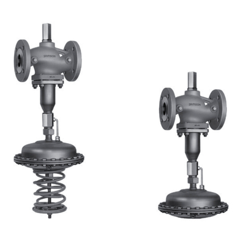
The regulators basically consist of a valve
with a seat, plug and restriction as well as a
closing actuator with an operating dia-
phragm. The valve and actuator are deliv-
ered in separate packaging and need to be
connected on site using the coupling nut (11).
The process medium flows through the valve
in the direction indicated by the arrow. The
free areas of flow released by the orifice (1.4)
and the valve plug (3) determine the flow rate
V
.and the differential pressure Δpplant across
the plant.
Fully balanced valves ensure that the up-
stream and downstream forces acting on the
valve plug are eliminated by a balancing bel-
lows (5) or a balancing diaphragm (5.1). The
principle of operation of the regulators with
valves balanced by a bellows or by a dia-
phragm only differ concerning their pressure
balancing. Valves balanced by a diaphragm
(DN 125 to 250 only) have a balancing dia-
phragm instead of a balancing bellows (5).
The pressure downstream of the orifice (1.4)
acts on the outer surface of the metal bellows
or balancing diaphragm and the down-
stream pressure on the inside of the bellows
or diaphragm. As a result, the forces created
by the upstream and downstream pressures
acting on the valve plug are equally bal-
anced.
The regulators in sizes DN 15 to 100 are
equipped with a connecting piece (10) for the
low-pressure control line between the valve
and the actuator.
In differential pressure control, the high pres-
sure (flow) of the plant is transmitted to the
bottom diaphragm chamber of the actuator
over the high-pressure control line. The pres-
sure downstream of the orifice (1.4) acts on
the top diaphragm chamber over the hollow
plug stem and the connected low-pressure
control line. The differential pressure is con-
verted into a positioning force at the dia-
phragm (13) and is used to change the posi-
tion of the valve plug according to the force of
the set point springs (16). Depending on the
version of the actuator, the set point springs
are installed in the actuator to provide a fixed
set point (Type 42-38), or they are located
outside to allow the set point to be adjusted as
required (Type 42-34).
The restriction (1.1) is used to adjust the flow
limitation.
The force limiter (20) as well as the internal
excess pressure limiter (21) are designed to
protect the seat (2) and plug (3) against over-
load in case of extreme operating conditions.
4EB 3013 EN
Design and principle of operation
Table 1 · Regulator configuration
Controller = Valve + Actuator
Type 42-34 with connecting piece (for DN 15 to 100) Type 2423 Balanced Type 2424 Adjustable set point
Type 42-38 with connecting piece Type 2423 Balanced Type 2428 Fixed set point
