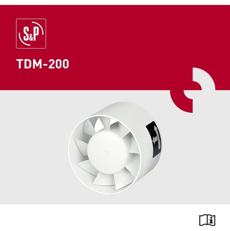
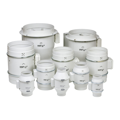
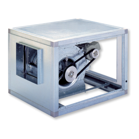
S&P JENcoFAN Losone Select Series User manual

Losone Select Series
Ceiling/Wall Mount Ventilators
Installation, Operation and Maintenance Manual
Models: L100, L150, L200, L250 & L300
READ AND SAVE THESE INSTRUCTIONS
The purpose of this manual is to aid in the proper installation and operation of fans manufactured by S&P USA.
These instructions are intended to supplement good general practices and are not intended to cover detailed
instruction procedures, because of the wide variety and types of fans manufactured by S&P USA.
6393 Powers Avenue
Jacksonville, FL 32217
P: 800.961.7370
F: 800.961.7379
LosoneSeries_IOM_03232022

1
Losone Select Ceiling Mount Ventilation
Models: L100, L150, L200, L250 & L300
CEILING/WALL-MOUNT
VENTILATORS • 120V
READ AND SAVE THESE INSTRUCTIONS
WARNING
CAUTION
TABLE OF CONTENTS
TO REDUCE THE RISK OF FIRE, ELECTRIC SHOCK, OR INJURY
TO PERSONS, OBSERVE THE FOLLOWING:
1. Use this unit only in the manner intended by the manufacturer.
If you have questions, contact the manufacturer at the address
or telephone number listed in the warranty.
2. Before servicing or cleaning unit, switch power off at service
panel and lock the service disconnecting means to prevent
power from being switched on accidentally. When the service
disconnecting means cannot be locked, securely fasten a
prominent warning device, such as a tag, to the service panel.
3. Installation work and electrical wiring must be done by a
qualified person(s) in accordance with all applicable codes
and standards, including fire-rated construction codes and
standards.
4. Sufficient air is needed for proper combustion and exhausting
of gases through the flue (chimney) of fuel burning equipment
to prevent backdrafting. Follow the heating equipment
manufacturer’s guideline and safety standards such as those
published by the National Fire Protection Association (NFPA),
and the American Society for Heating, Refrigeration and
Air Conditioning Engineers (ASHRAE), and the local code
authorities.
5. When cutting or drilling into wall or ceiling, do not damage
electrical wiring and other hidden utilities.
6. Ducted fans must always be vented to the outdoors.
7. To reduce the risk of fire, use only metal ductwork.
8. If this unit is to be installed over a tub or shower, it must be
marked as appropriate for the application and be connected
to a GFCI (Ground Fault Interrupter) - protected branch circuit.
9. Never place a switch where it can be reached from a tub or
shower.
10.This unit must be grounded.
This manual is divided into sections as follows:
• “TYPICAL INSTALLATION” This section shows a common
installation in new and existing, frame construction.
- Mounting (new construction)
- Mounting (existing construction)
- Wiring
- Ducting (horizontal blower discharge)
• “MOUNTING OPTIONS”
• “WIRING OPTIONS”
-Wiring Plate Position
• “DUCTING OPTIONS”
- Blower Discharge Positions
- Ducting (vertical blower discharge)
• “USE AND CARE”
• “SERVICE PARTS”
• “WARRANTY”
1. For general ventilating use only. Do not use to exhaust
hazardous or explosive materials and vapors.
2. To avoid motor bearing damage and noisy and/or
unbalanced impellers, keep drywall spray, construction dust,
etc. off power unit.
3. Please read specification label on product for further
information and requirements.
Installer: Leave this manual
with the homeowner.
Homeowner: Use and Care
information on page 3.

2
Losone Select Ceiling Mount Ventilation
Models: L100, L150, L200, L250 & L300
TYPICAL INSTALLATION TYPICAL INSTALLATION
CEILING JOIST
(16” centers shown)
ROUND DUCT*
GRILLE
(Install after
ceiling is
nished.)
MOUNTING
SCREW
GRILLE
SCREW
Blower factory-shipped
in horizontal
discharge position.
Mounting brackets
factory-shipped in
position for ½”
ceiling material.
ADDITIONAL
1½” FRAMING
WIRING
PLATE
WHITE
TO
WHITE
BLACK
TO
BLACK TOP / BACK
OF HOUSING
120 VAC LINE IN
GROUNDTO
WIRING PLATE
ROOF CAP
ROUND
ELBOW*
ROUND
DUCT*
WALL
CAP
CEILING
ROUND DUCT*
GRILLE
SCREW
FINISHED
MATERIAL
GRILLE
(Polymeric shown)
CEILING JOIST
(16” centers
shown)
(wide side down)
opposite sides
MOUNTING
BRACKETS
(Attached to
of housing &
upside-down,
so housing is
ush with
nished ceiling)
MOUNTING (New Frame Construction) WIRING
DUCTING (Horizontal blower discharge)MOUNTING (Existing Frame Construction)
Factory-shipped unit installed in new construction.
Ventilator can be wired from outside of housing.
Use UL approved connectors to wire per local codes.
Two ways to connect ductwork to a factory-shipped unit.
Factory-shipped unit installed in new construction.
*L100 & L150 use 6” round duct.
*L200, L250 * L300 use 8” round duct.
IMPORTANT:
Remove shipping tape from damper
Remove the shipping tape from the damper flap and make sure
that damper flap opens and closes freely inside the ductwork.
Use duct tape to make ductwork connections secure and air-tight.
Remove shipping ring from blower inlet
Remove the shipping ring from the blower inlet before operating
the ventilator.
*L100 & L150 use 6” round duct.
*L200, L250 * L300 use 8” round duct.

3
MOUNTING OPTIONS
Mounting brackets in
factory-shipped position.
(Outlet parallel to joists.)
(New construction)
Mounting brackets mounted
to outlet sides of housing.
(Outlet perpendicular to joists.)
(New construction)
Mounting brackets mounted
to top of sides of housing.
(Outlet parallel to joists.)
(New or existing construction)
Mounting brackets flipped
over and mounted to outlet
sides of housing.
(Outlet parallel to joists.)
(Existing construction)
Mounting brackets flipped
over to give approx. 1”
more clearance.
(Outlet parallel to joists.)
(New construction)
Mounting brackets flipped
over and mounted to top of
sides of housing.
(Outlet parallel to joists.)
(New or existing construction)
¼-20 hex nuts secure mounting brackets to housing.
Loosen and re-tighten or remove and replace nuts
as necessary for desired mounting bracket position.
12¼"
to
91
/
2"
101
/
2"
12¼"
1½"
to
2½"
12¼"
1
1
/
8
"
MAX.
12¼"
to
10
3
/
4
"
11
3
/
4
"
12¼"
12¼"
to
11
/
2"
21
/
2"
12¼"
to
91
/
2"
101
/
2"
12¼"
1½"
to
2½"
12¼"
1
1
/
8
"
MAX.
12¼"
to
10
3
/
4
"
11
3
/
4
"
12¼"
12¼"
to
11
/
2"
21
/
2"
12¼"
to
91
/
2"
101
/
2"
12¼"
1½"
to
2½"
12¼"
1
1
/
8
"
MAX.
12¼"
to
10
3
/
4
"
11
3
/
4
"
12¼"
12¼"
to
11
/
2"
21
/
2"
WIRING OPTIONS
Wiring plate mounts to side or top of housing.
WIRING PLATE
POSITION
HORIZONTAL POWER
CABLE CONNECTION
VERTICAL
POWER
CABLE
CONNECTION
Losone Select Ceiling Mount Ventilation
Models: L100, L150, L200, L250 & L300
DUCTING OPTIONS
BLOWER DISCHARGE POSITIONS
DUCT CONNECTOR
BLOWER
Change
blower &
duct
connector
positions for
vertical
discharge.
DUCT CONNECTOR
BLOWER
Blower and duct connector
in horizontal discharge
position. (Factory shipped)
Blower and duct
connector in vertical
discharge position.
ROUND
DUCT*
ROOF CAP
DUCTING (Vertical blower discharge)
Typical ductwork connection to a
ventilator converted to vertical discharge.
*L100 & L150 use 6” round duct.
*L200, L250 * L300 use 8” round duct.
USE AND CARE
Ventilator is designed for continuous operation. If desired,
it may be controlled using an on/off switch or a solid-state,
variable speed control. Follow wiring instructions packed
with control, and adhere to all local and state codes, and
the National Electrical Code.
WARNING: To reduce the risk of electric shock,
disconnect from power supply before servicing.
To clean grille: Use appropriate vacuum attachment or
remove grille and clean with a soft cloth and mild soap or
detergent. Dry grille thoroughly before reinstalling.
To clean blower assembly: Remove grille, unplug blower
from housing, remove blower mounting nuts, and carefully
remove blower from housing. Use appropriate vacuum
attachment or a soft cloth and mild soap or detergent to
clean blower discharge area and wheel. DO NOT ALLOW
WATER TO ENTER MOTOR. Make sure blower assembly is
completely dry before reinstalling.
Motor is permanently lubricated. Do not oil or disassemble motor.

4
SERVICE PARTS SERVICE PARTS
Losone Select Ceiling Mount Ventilation
Models: L100, L150, L200, L250 & L300
KEY NO. PART NO. DESCRIPTION
197014725 Housing Assembly (L100 & L150)
97014726 Housing Assembly (L200, L250
& L300)
297014728 Mounting Bracket (2 req.)
39701476 0 Damper Assembly (6” dia.)
97014761 Damper Assembly (8” dia.)
499150415 Screw, 8-18 x ¼ (12 req.)*
5 98005513 Wire Box Cover
6 99400035 Strain Relief Bushing
7 98005512 Wiring Plate
899150471 Ground Screw, 10-32 x ½ (2 req.)
997014 774 Scroll Assembly (L100 & L150)
970147 75 Scroll Assembly (L200, L250
& L300)
10 98009399 Inlet Ring
11 99110805 Blower Wheel
12 99080481 Motor (L100)
99080482 Motor (L150)
99080483 Motor (L200)
99080484 Motor (L250)
99080485 Motor (L300)
13 99260558 Lock Nut, 8-32 (4 req.)*
14 99250959 Washer (4 req.)*
15 99100491 Grommet (4 req.)
Blower Assembly, Complete
(Includes Key Nos. 4 & 9-15)
97014800 Motor (L100)
97014801 Motor (L150)
97014802 Motor (L200)
97014803 Motor (L250)
97014804 Motor (L300)
16 99260477 Nut, ¼-20 (6 req.)*
17 97006039 Wire Harness
18 99500390 Wrapper Insulation
19 99500391 Side Insulation (2 req.)
20 99420466 Insulation Mounting Clip
21 99110807 Grille
22 99420470 Grille Nut (2 req.)
23 99150472 Grille Mounting Screw (2 req.)
24 99150591 Screw, 10-16 x 7/8 (4 req.)*
Order replacement parts by PART NO. - not by KEY NO.
* Standard hardware - may be purchased locally.
1
2
3
4
5
6
7
8
9
10
11
12
13
14
17
18
19
19
20
20
21
23
24
16
15
4
25
25
16
4
4
BLOWER
ASSEMBLY
WARRANTY
ONE YEAR LIMITED WARRANTY
Soler & Palau Breidert Air Products JencoFan, warrants all products to be free from defects in material or workmanship for a period of one year
from date of shipment. If it appears within one year from date of shipment by the Company to the original purchaser that any such ventilator or the
material used therein does not meet the warranties specified above and the purchaser notifies the Company promptly, the Company agrees to
remedy any such defect, at the company’s option.
This warranty shall not apply to any equipment which has been repaired or altered in any way so as, in the company’s judgement, to affect its
performance or reliability, nor which has been improperly installed or subjected to misuse, negligence, or accident. Neither shall this warranty apply
to labor to remove or install defective parts, profits lost due to failure of the ventilator or electric motors or belts. Electric motors, however, carry the
warranty of the motor manufacturer.
This warranty is expressly in lieu of all other warranties expressed or implied, and of all other obligations or liabilities on the company’s part. The company
neither assumes, nor authorizes any representative or other persons to assume for it, any other liability in connection with the sale of its equipment.
Soler & Palau
Breidert Air Products
JencoFan
6393 Powers Ave
Jacksonville, FL 32217

5
Losone Select Ceiling Mount Ventilation
Modèles: L100, L150, L200, L250 & L300
VENTILATEURS MONTAGE
AU PLAFOND•120V
LIRE ET CONSERVER CES INSTRUCTIONS
AVERTISSEMENT
ATTENTION
TABLE DES MATIÈRES
POUR RÉDUIRE LE RISQUE D´INCENDIE, DE CHOC ÉLECTRIQUE
OU DE BLESSURES PERSONNELLES, OBSERVEZ CE QUI SUIT:
1. Utilisez cette unité seulement de la façon prévue par le
fabricant. Pour d´autres renseignements, contactez le fabricant
à l´adresse ou au numéro de téléphone qui se trouve dans
la garantie.
2. Avant d’effectuer une réparation ou un entretien sur cet
appareil, coupez le courant au tableau d’alimentation et
verrouillez celui-ci pour empêcher que la tension soit remise
accidentellement. Lorsque le verrouillage de la déconnexion
n’est pas possible, mettez bien en vue un signal d’avertissement
telle qu’une étiquette, sur le panneau d’alimentation.
3. L´installation et la pose des fils électriques doivent être
effectuées par une ou des personnes qualifiées conformément
à tous les codes et normes applicables, incluant les normes de
construc-tion en rapport aux incendies.
4. Il faut suffisamment d´air pour une combustion appropriée
et l´échappement des gaz par le tuyau de la cheminée de
l´équipement brûlant du combustible pour prévenir un contre-
courant. Suivez les instructions du fabricant de l´équipement de
chauffage et les normes de sécurité telles que celles publiées par
la National Fire Protection Association (NFPA) et l´American
Society for Heating, Refrigeration and Air Conditioning
Engineers (ASHRAE) et des autorités du code local.
5. Lors de la coupe ou du perçage dans un mur ou un plafond,
prenez soin de ne pas endommager les fils électriques et les
autres utilités dissimulées.
6. La décharge des ventilateurs à conduit par l´évent doit
toujours se faire à l´extérieur.
7. Pour réduire le rsque d’incendie, utilisez seulement des
donduits de ventilation en métal.
8. Si cette unité doit être installée au-dessus d’une baignoire ou
d’une douche, elle doit être marquée comme étant appropriée
pour l’application et être connectée à un circuit dérivé protége
GFCI (interrupteur de circuit en cas de défaut de mise à la
terre du neutre).
9. Ne placez jamais un interrupteur dans un endroit où il peut
être rejoint d’une baignoire ou d’une douche.
10.Cette unité doit être mise à la terre.
Ce manuel se divise comme suit :
• INSTALLATION TYPIQUE
Cette section montre une installation standard dans un bâtiment en
cours de construction ou déjà construit.
- Montage (construction en cours)
- Montage (construction terminée)
- Câblage
- Installation des conduits (décharge de soufflerie horizontale)
• OPTIONS DE MONTAGE
• OPTIONS DE CÂBLAGE
- Position de la plaque de câblage
• OPTIONS D’INSTALLATION DES CONDUITS
- Positions de la décharge de la soufflerie
- Installation des conduits (décharge de soufflerie verticale)
• UTILISATION ET ENTRETIEN
• PIÈCES DE RECHANGE
• GARANTIE
1. Pour ventilation générale seulement. Ne l´utilisez pas pour évacuer
les vapeurs ou matériaux dangereux ou que peuvent exploser.
2. Pour éviter d´endommager les coussinets du moteur et des
tur-bines bruyantes et/ou mal équilibrées, assurez que l´unité
motrice est exempte de poussière provenant des murs en
pierres sèches et la construction.
3. Veuillez lire l´étiquette de spécifications sur le produit pour
d´autres renseignements et exigences.
Installateur: Remetez ce manuel
au protpriétaire de maison.
Propriétaire de maison: Mode
d’utilisation et soin à la page 7.

6
Losone Select Ceiling Mount Ventilation
Modèles: L100, L150, L200, L250 & L300
INSTALLATION TYPIQUE INSTALLATION TYPIQUE
SOLIVE DE
PLAFOND
(16 po / 40,6 cm
centre)
CONDUIT CIRCULAIRE*
GRILLE
(en polymère)
À installer après
la nition du
plafond.
VIS DE
FIXATION
VIS DE
GRILLE
Souerie préassemblée en
position de décharge
horizontale
Supports
préassemblés pour
plafonds de ½ po (1,27
cm) d’épaisseur.
CHARPENTE
SUPPLÉMENTAIRE DE
1½ po (3,81 cm)
PLAQUE
DE
CÂBLAGE
NOIR AU
NOIR
BLANC AU
BLANC
DESSUS /
ARRIÈRE DU
BOÎTIER
ENTRÉE 120 VCA
FIL DE TERRE À
PLAQUE DE
CÂBLAGE
CHAPEAU DE TOIT
COUDE
CIRCULAIRE*
CONDUIT
CIRCULAIRE*
CHAPEAU
DE MUR
CONDUIT CIRCULAIRE*
DE PLAFOND
MATÉRIAU
FINI
GRILLE (en
polymère)
SOLIVE DE
PLAFOND (16 po /
40,6 cm centre)
CHARPENTE 2 x 4 (côté
large en bas)
SUPPORTS
(xés aux
autres côtés
du boîtier et à
que le boîtier
soit au ras du
l’envers pour
plafond ni)
VIS DE
GRILLE
MONTAGE (Construction en cours) CÂBLAGE
INSTALLATION DES CONDUITS
(décharge de soufflerie horizontale)
MONTAGE (construction terminée)
Appareil installé dans un bâtiment en cours de construction.
Le ventilateur peut être branché depuis l’extérieur du boîtier.
Utiliser des connecteurs homologués UL pour les
branchements, conformément aux codes locaux en vigueur.
Deux manières de raccorder les conduits à un appareil prémonté.
Appareil installé dans un bâtiment déjà construit.
*L100 et L150 utilise conduit circulaire de 15,2 cm (6 pouce).
*L200, L250 et L300 utilise conduit circulaire de 20,3 cm (8 pouce).
IMPORTANTE:
Retirez la bande d’expédition de l’amortisseur.
Veiller à retirer le ruban adhésif d’expédition du volet du registre et
s’assurer que ce dernier s’ouvre et se ferme librement à l’intérieur
du conduit. Utiliser du ruban adhésif pour assurer et étancher les
raccords des conduits.
Retirez la boucle d’expédition de la prise
de ventilateur.
Retirez la boucle d’expédition de la prise de ventilateur avant
d’actionner le ventilateur.
*L100 et L150 utilise conduit circulaire de 15,2 cm (6 pouce).
*L200, L250 et L300 utilise conduit circulaire de 20,3 cm (8 pouce).

7
OPTIONS DE MONTAGE
Supports en position
préassemblée
(Sortie parallèle aux solives)
(Bâtiment en cours
de construction)
Supports fixés de part et
d’autre de la sortie du boîtier
(Sortie perpendiculaire aux
solives) (Bâtiment en cours
de construction)
Supports fixés sur le dessus, de
part et d’autre du boîtier
(Sortie parallèle aux solives)
(Bâtiment en cours de
construction ou déjà construit)
Supports retournés et fixés
de part et d’autre de la
sortie du boîtier
(Sortie perpendiculaire aux
solives) (Bâtiment déjà
construit)
Supports retournés pour
donner environ1 po de
dégagement supplémentaire
(Sortie perpendiculaire aux
solives) (Bâtiment en cours
de construction)
Supports retournés et fixés
sur le dessus, de part et
d’autre du boîtier
(Sortie parallèle aux solives)
(Bâtiment en cours de
construction ou déjà construit)
Des écrous à six pans ¼-20 fixent les supports au boîtier.
Desserrer et resserrer ou retirer et replacer les écrous si
nécessaire, selon la position désirée pour le support.
31,8cm
3,8 a
6,4
cm
31,8cm
2,9cm
MAX.
31,8cm
3,8 a
6,4
cm
31,8cm
31,8cm
31,8cm
24,1 a
26,7
cm
27,3 a
29,9
cm
31,8cm
3,8 a
6,4
cm
31,8cm
2,9cm
MAX.
31,8cm
3,8 a
6,4
cm
31,8cm
31,8cm
31,8cm
24,1 a
26,7
cm
27,3 a
29,9
cm
31,8cm
3,8 a
6,4
cm
31,8cm
2,9cm
MAX.
31,8cm
3,8 a
6,4
cm
31,8cm
31,8cm
31,8cm
24,1 a
26,7
cm
27,3 a
29,9
cm
OPTIONS DE CÂBLAGE
La plaque de câblage se fixe sur le côté
ou sur le dessus du boîtier.
POSITION DE LA
PLAQUE DE CÂBLAGE
BRANCHEMENT DU
CÂBLE D’ALIMENTATION
À L’HORIZONTALE
BRANCHEMENT
DU CÂBLE
D’ALIMENTATION
À LA VERTICALE
Losone Select Ceiling Mount Ventilation
Modèles: L100, L150, L200, L250 & L300
OPTIONS D’INSTALLATION
DES CONDUITS
POSITIONS DE LA DÉCHARGE DE LA SOUFFLERIE
RACCORD DE CONDUIT
SOUFFLERIE SOUFFLERIE
Modier la
position du
raccord de
souerie et
de conduit
pour une
décharge
verticale.
RACCORD DE CONDUIT
Raccord de soufflerie et de
conduit en position de
décharge horizontale
(préassemblée)
Raccord de soufflerie et de
conduit en position de
décharge verticale
CONDUIT
CIRCULAIRE*
CHAPEAU DE TOIT
INSTALLATION DES CONDUITS
(décharge de soufflerie verticale)
Raccordement de conduit typique à
un ventilateur converti en décharge verticale
*FF100 et FF150 utilise conduit circulaire de 15,2 cm (6 pouce).
*FF200, FF250 et FF300 utilise conduit circulaire de 20,3 cm (8 pouce).
UTILISATION ET ENTRETIEN
Le ventilateur a été conçu pour une utilisation continue. Si désiré, il
peut être commandé à l’aide d’un interrupteur marche/arrêt ou d’un
régulateur de vitesse à semi-conducteurs. Suivre les instructions de
câblage fournies avec le régulateur et respecter tous les codes locaux et
provinciaux en vigueur, de même que le Code national de l’électricité
AVERTISSEMENT : Pour diminuer les risques de
décharge électrique, débrancher la source d’alimentation
avant toute opération d’entretien.
Pour nettoyer la grille: Utiliser un accessoire d’aspirateur approprié
ou retirer la grille et nettoyer à l’aide d’un chiffon doux et de savon
ou de détergent doux. Bien essuyer la grille avant de la réinstaller.
Pour nettoyer la soufflerie: Retirer la grille, débrancher la soufflerie
du boîtier, retirer les écrous de fixation de la soufflerie et retirer
délicatement la soufflerie du boîtier. Utiliser un accessoire
d’aspirateur approprié ou retirer la grille et nettoyer à l’aide d’un
chiffon doux et de savon ou de détergent doux pour nettoyer la
zone de décharge de la soufflerie et la roue. NE PAS LAISSER
D’EAU S’INFILTRER DANS LE MOTEUR. S’assurer que la soufflerie
est complètement sèche avant de la réinstaller.
Le moteur est lubrifié en permanence. Ne pas lubrifier ou démonter
le moteur.

8
PIÈCES DE RECHANGE PIÈCES DE RECHANGE
Losone Select Ceiling Mount Ventilation
Modèles: L100, L150, L200, L250 & L300
LÉGENDELÉGENDE No DE RÉF. DESCRIPTION
197014725 Boîtier (L100 & L150)
97014726 Boîtier (L200, L250 & L300)
297014728 Support (2 oblig.)
39701476 0 Registre (diam. 6 po)
97014761 Registre (diam. 8 po)
499150415 Vis, 8-18 x ¼ (12 oblig.)*
5 98005513 Couvercle de la boîte de câblage
6 99400035 Réducteur de tension
7 98005512 Plaque de câblage
899150471 Vis de terre, 10-32 x ½ (2 oblig.)
997014 774 Volute (L100 & L150)
970147 75 Volute (L200, L250 & L300)
10 98009399 Bague d’arrivée
11 99110805 Roue de soufflerie
12 99080481 Moteur (L100)
99080482 Moteur (L150)
99080483 Moteur (L200)
99080484 Moteur (L250)
99080485 Moteur (L300)
13 99260558 Écrou, 8-32 ( 4 oblig.)*
14 99250959 Rondelle (4 oblig.)*
15 99100491 Bague d’étoupe (4 oblig.)*
Soufflerie, ensemble
(inclut no légende 4 et 9 à 15)
97014800 Moteur (L100)
97014801 Moteur (L150)
97014802 Moteur (L200)
97014803 Moteur (L250)
97014804 Moteur (L300)
16 99260477 Écrou, ¼-20 (6 oblig.)*
17 97006039 Harnais à fils
18 99500390 Enveloppe isolante
19 99500391 Isolant latéral (2 oblig.)
20 99420466 Pince de montage d’isolant
21 99110807 Grille
22 99420470 Écrou de grille (2 oblig.)
23 99150472 Vis de fixation de grille (2 oblig.)
24 99150591 Vis, 10-16 x 7/8 (4 oblig.)*
Commander les pièces de rechange par numéro de référence et
non à l’aide du numéro de légende.
* Visserie standard - peut être achetée localement.
1
2
3
4
5
6
7
8
9
10
11
12
13
14
17
18
19
19
20
20
21
23
24
16
15
4
25
25
16
4
4
ENSEMBLE DE
SOUFFLERIE
GARANTIE
GARANTIE LIMITÉE D’UN AN
Soler & Palau Breidert Air Products JencoFan garantit ses produits contre tout défaut de matériau ou de fabrication pendant une année, à compter
de la date d’expédition. S’il s’avère, moins d’un an après que la société ait expédié le produit à l’acheteur initial, que le ventilateur ou les matériaux
qui le composent ne respectent pas les garanties stipulées ci-haut, dans la mesure où l’acheteur en a promptement avisé la société, celle-ci
s’engage à corriger lesdites défectuosités, à sa seule option, en réparant toute pièce défectueuse ou en fournissant à l’usine de la société une
pièce réparée ou de rechange.
La présente garantie ne s’applique à aucun équipement qui aura été modifié ou réparé de telle sorte, selon l’opinion de la société, à affecter ses
performances ou sa fiabilité, ou qui aura été mal installé ou fait l’objet d’une mauvaise utilisation, d’une négligence ou d’un accident. Cette garantie
ne couvre ni la main-d’oeuvre nécessaire pour le démontage ou l’installation de pièces, ni les pertes de profit attribuables à une défaillance du
ventilateur, des moteurs électriques ou des courroies. Les moteurs électriques sont toutefois couverts par la garantie de leur fabricant. Les pièces
défectueuses doivent être renvoyées à la société avant l’émission d’aucun crédit. Ces pièces doivent être retournées tous frais de port payés. Les
expéditions en port dû ou contre remboursement seront refusées.
Cette garantie remplace formellement toute autre garantie expresse ou tacite, ainsi que toute autre obligation ou responsabilité de la part de
la société. Celle-ci n’assume aucune autre responsabilité relative à la vente de ses équipements et n’autorise aucun de ses représentants ou
quiconque à l’assumer en son nom.
Soler & Palau/Breidert Air Products/JencoFan
6393 Powers Ave
Jacksonville, FL 32217

Losone Select Series
Inline/Cabinet Ventilators
Installation, Operation and Maintenance Manual
Models: L100L, L150L, L200L, L250L & L300L
READ AND SAVE THESE INSTRUCTIONS
The purpose of this manual is to aid in the proper installation and operation of fans manufactured by S&P USA.
These instructions are intended to supplement good general practices and are not intended to cover detailed
instruction procedures, because of the wide variety and types of fans manufactured by S&P USA.
6393 Powers Avenue
Jacksonville, FL 32217
P: 800.961.7370
F: 800.961.7379
LosoneSeries_IOM_03232022

1
Losone Select Inline Mount Ventilation
Models: L100L, L150L, L200L, L250L & L300L
IN-LINE
VENTILATORS • 120V
READ AND SAVE THESE INSTRUCTIONS
WARNING
CAUTION
TABLE OF CONTENTS
TO REDUCE THE RISK OF FIRE, ELECTRIC SHOCK, OR INJURY
TO PERSONS, OBSERVE THE FOLLOWING:
1. Use this unit only in the manner intended by the manufacturer.
If you have questions, contact the manufacturer at the address
or telephone number listed in the warranty.
2. Before servicing or cleaning unit, switch power off at service
panel and lock the service disconnecting means to prevent
power from being switched on accidentally. When the service
disconnecting means cannot be locked, securely fasten a
prominent warning device, such as a tag, to the service panel.
3. Installation work and electrical wiring must be done by a
qualified person(s) in accordance with all applicable codes
and standards, including fire-rated construction codes and
standards.
4. Sufficient air is needed for proper combustion and exhausting
of gases through the flue (chimney) of fuel burning equipment
to prevent backdrafting. Follow the heating equipment
manufacturer’s guideline and safety standards such as those
published by the National Fire Protection Association (NFPA),
and the American Society for Heating, Refrigeration and
Air Conditioning Engineers (ASHRAE), and the local code
authorities.
5. When cutting or drilling into wall or ceiling, do not damage
electrical wiring and other hidden utilities.
6. Ducted fans must always be vented to the outdoors.
7. To reduce the risk of fire, use only metal ductwork.
8. If this unit is to be installed over a tub or shower, it must be
marked as appropriate for the application and be connected
to a GFCI (Ground Fault Interrupter) - protected branch circuit.
9. Never place a switch where it can be reached from a tub or
shower.
10.This unit must be grounded.
This manual is divided into sections as follows:
• “TYPICAL INSTALLATION” This section shows a common
installation in new and existing, frame construction.
- Mounting (new construction)
- Mounting (existing construction)
- Wiring
- Ducting (horizontal blower discharge)
• “MOUNTING OPTIONS”
• “WIRING OPTIONS”
-Wiring Plate Position
• “DUCTING OPTIONS”
- Blower Discharge Positions
- Ducting (right angle blower discharge)
• “USE AND CARE”
• “SERVICE PARTS”
• “WARRANTY”
1. For general ventilating use only. Do not use to exhaust
hazardous or explosive materials and vapors.
2. To avoid motor bearing damage and noisy and/or unbalanced
impellers, keep drywall spray, construction dust, etc. off power unit.
3. If ventilator is installed in an unconditioned space (such
as an attic): Surround the ventilator with thermal insulation
- to minimize possible condensation.
4. Please read specification label on product for further
information and requirements.
Installer: Leave this manual
with the homeowner.
Homeowner: Use and Care
information on page 3.

2
Losone Select Inline Mount Ventilation
Models: L100L, L150L, L200L, L250L & L300L
TYPICAL INSTALLATION TYPICAL INSTALLATION
CEILING
CEILING JOIST
(16” centers shown)
ROUND DUCT*
MOUNTING
SCREW
Blower factory-shipped
in straight through
discharge position.
Mounting brackets
factory-shipped in
position for ½”
ceiling material.
ADDITIONAL
1½” FRAMING
WIRING
PLATE
WHITE
TO
WHITE
BLACK
TO
BLACK TOP / BACK
OF HOUSING
120 VAC LINE IN
GROUNDTO
WIRING PLATE
ROUND DUCT*
FINISHED
MATERIAL
CEILING JOIST
(16” centers
shown)
2 X 4 FRAMING
(wide side down)
opposite sides
of housing &
MOUNTING
BRACKETS
(Attached to
upside-down)
ROOF CAP
ROUND
ELBOW*
ROUND DUCT*
WALL
CAP
CEILING
CEILING JOIST
(16” centers shown)
ROUND DUCT*
MOUNTING
SCREW
Blower factory-shipped
in straight through
discharge position.
Mounting brackets
factory-shipped in
position for ½”
ceiling material.
ADDITIONAL
1½” FRAMING
WIRING
PLATE
WHITE
TO
WHITE
BLACK
TO
BLACK TOP / BACK
OF HOUSING
120 VAC LINE IN
GROUNDTO
WIRING PLATE
ROUND DUCT*
FINISHED
MATERIAL
CEILING JOIST
(16” centers
shown)
2 X 4 FRAMING
(wide side down)
opposite sides
of housing &
MOUNTING
BRACKETS
(Attached to
upside-down)
ROOF CAP
ROUND
ELBOW*
ROUND DUCT*
WALL
CAP
MOUNTING (New Frame Construction) WIRING
DUCTING (Horizontal blower discharge)MOUNTING (Existing Frame Construction)
Factory-shipped unit installed in new construction.
Ventilator can be wired from outside of housing.
Use UL approved connectors to wire per local codes.
Two ways to connect ductwork to a factory-shipped unit.
Factory-shipped unit installed in new construction.
*L100L & L150L use 6” round duct.
*L200L, L250L & L300L use 8” round duct. IMPORTANT:
Remove shipping tape from damper
Remove the shipping tape from the damper flap and make sure
that damper flap opens and closes freely inside the ductwork.
Use duct tape to make ductwork connections secure and air-tight.
Remove shipping ring from blower inlet
Remove the shipping ring from the blower inlet before operating
the ventilator.
*L100L & L150L use 6” round duct.
*L200L, L250L & L300L use 8” round duct.

3
MOUNTING OPTIONS
Mounting brackets in
factory-shipped position.
(Outlet parallel to joists.)
(New construction)
Mounting brackets mounted
to outlet sides of housing.
(Outlet perpendicular to joists.)
(New construction)
Mounting brackets mounted
to top of sides of housing.
(Outlet parallel to joists.)
(New or existing construction)
Mounting brackets flipped
over and mounted to outlet
sides of housing.
(Outlet parallel to joists.)
(Existing construction)
Mounting brackets flipped
over to give approx. 1”
more clearance.
(Outlet parallel to joists.)
(New construction)
Mounting brackets flipped
over and mounted to top of
sides of housing.
(Outlet parallel to joists.)
(New or existing construction)
¼-20 hex nuts secure mounting brackets to housing.
Loosen and re-tighten or remove and replace nuts
as necessary for desired mounting bracket position.
12¼"
to
91
/
2"
101
/
2"
12¼"
1½"
to
2½"
12¼"
1
1
/
8
"
MAX.
12¼"
to
10
3
/
4
"
11
3
/
4
"
12¼"
12¼"
to
1
1
/
2
"
2
1
/
2
"
DUCT CONNECTOR
BLOWER
Change
blower &
duct
connector
positions for
right angle
discharge.
ROOF CAP
ROUND
DUCT*
BLOWER
DUCT CONNECTOR
12¼"
to
91
/
2"
101
/
2"
12¼"
1½"
to
2½"
12¼"
1
1
/
8
"
MAX.
12¼"
to
10
3
/
4
"
11
3
/
4
"
12¼"
12¼"
to
1
1
/
2
"
2
1
/
2
"
DUCT CONNECTOR
BLOWER
Change
blower &
duct
connector
positions for
right angle
discharge.
ROOF CAP
ROUND
DUCT*
BLOWER
DUCT CONNECTOR
12¼"
to
91
/
2"
101
/
2"
12¼"
1½"
to
2½"
12¼"
1
1
/
8
"
MAX.
12¼"
to
10
3
/
4
"
11
3
/
4
"
12¼"
12¼"
to
1
1
/
2
"
2
1
/
2
"
DUCT CONNECTOR
BLOWER
Change
blower &
duct
connector
positions for
right angle
discharge.
ROOF CAP
ROUND
DUCT*
BLOWER
DUCT CONNECTOR
WIRING OPTIONS
Wiring plate mounts to side or top of housing.
WIRING PLATE
POSITION
HORIZONTAL POWER
CABLE CONNECTION
VERTICAL
POWER
CABLE
CONNECTION
Losone Select Inline Mount Ventilation
Models: L100L, L150L, L200L, L250L & L300L
DUCTING OPTIONS
BLOWER DISCHARGE POSITIONS
12¼"
to
9
1
/
2
"
10
1
/
2
"
12¼"
1½"
to
2½"
12¼"
1
1
/
8
"
MAX.
12¼"
to
10
3
/
4
"
11
3
/
4
"
12¼"
12¼"
to
11
/
2"
21
/
2"
DUCT CONNECTOR
BLOWER
Change
blower &
duct
connector
positions for
right angle
discharge.
ROOF CAP
ROUND
DUCT*
BLOWER
DUCT CONNECTOR
Blower and duct connector in
straight through discharge position.
(Factory shipped)
Blower and duct connector in
right angle discharge position.
12¼"
to
91
/
2"
101
/
2"
12¼"
1½"
to
2½"
12¼"
1
1
/
8
"
MAX.
12¼"
to
10
3
/
4
"
11
3
/
4
"
12¼"
12¼"
to
1
1
/
2
"
2
1
/
2
"
DUCT CONNECTOR
BLOWER
Change
blower &
duct
connector
positions for
right angle
discharge.
ROOF CAP
ROUND
DUCT*
BLOWER
DUCT CONNECTOR
DUCTING (Right angle blower discharge)
Typical ductwork connection to a ventilator
converted to right angle discharge.
*L100L & L150L use 6” round duct.
*L200L, L250L & L300L use 8” round duct.
USE AND CARE
Ventilator is designed for continuous operation. If desired,
it may be controlled using an on/off switch or a solid-state,
variable speed control. Follow wiring instructions packed
with control, and adhere to all local and state codes, and
the National Electrical Code.
WARNING: To reduce the risk of electric shock,
disconnect from power supply before servicing.
To clean blower assembly: Remove access panel, unplug
blower from housing, remove blower mounting nuts, and
carefully remove blower from housing. Use appropriate
vacuum attachment or a soft cloth and mild soap or
detergent to clean blower discharge area and wheel.
DO NOT ALLOW WATER TO ENTER MOTOR. Make sure
blower assembly is completely dry before reinstalling.
Motor is permanently lubricated. Do not oil or disassemble motor.

4
SERVICE PARTS SERVICE PARTS
Losone Select Inline Mount Ventilation
Models: L100L, L150L, L200L, L250L & L300L
KEY NO. PART NO. DESCRIPTION
197014735 Housing Assembly (L100L & L150L)
9701473 6 Housing Assembly (L200L, L250L)
& L300L)
297014728 Mounting Bracket (2 req.)
39701476 0 Damper Assembly (6” dia.)
97014761 Damper Assembly (8” dia.)
4 99390098 Duct Connector (6” dia.)
99390099 Duct Connector (8” dia.)
599150415 Screw, 8-18 x ¼ (12 req.)*
6 98005513 Wire Box Cover
7 99400035 Strain Relief Bushing
8 98005512 Wiring Plate
999150471 Ground Screw, 10-32 x ½ (2 req.)
10 97014 774 Scroll Assembly (L100L & L150L)
970147 75 Scroll Assembly (L200L, L250L
& L300L)
11 98009399 Inlet Ring
12 99110805 Blower Wheel
13 99080481 Motor (L100L)
99080482 Motor (L150L)
99080483 Motor (L200L)
99080484 Motor (L250L)
99080485 Motor (L300L)
14 99260558 Lock Nut, 8-32 (4 req.)*
15 99250959 Washer (4 req.)*
16 99100491 Grommet (4 req.)
Blower Assembly, Complete
(Includes Key Nos. 5 & 10-16)
97014800 (L100L)
97014801 (L150L)
97014802 (L200L)
97014803 (L250L)
97014804 (L300L)
17 99260477 Nut, ¼-20 (6 req.)*
18 97006039 Wire Harness
19 98009417 Access Panel
20 99420470 Cover Nut (2 req.)
21 99150472 Cover Mounting Screw (2 req.)
22 99150591 Screw, 10-16 x 7/8 (4 req.)*
Order replacement parts by PART NO. - not by KEY NO.
* Standard hardware - may be purchased locally.
1
2
3
5
6
7
8
9
10
11
12
13
14
15
18
19
20
21
17
16
5
22
22
16
5
5
5
4
BLOWER
ASSEMBLY
WARRANTY
ONE YEAR LIMITED WARRANTY
Soler & Palau Breidert Air Products JencoFan, warrants all products to be free from defects in material or workmanship for a period of one year
from date of shipment. If it appears within one year from date of shipment by the Company to the original purchaser that any such ventilator or the
material used therein does not meet the warranties specified above and the purchaser notifies the Company promptly, the Company agrees to
remedy any such defect, at the company’s option.
This warranty shall not apply to any equipment which has been repaired or altered in any way so as, in the company’s judgement, to affect its
performance or reliability, nor which has been improperly installed or subjected to misuse, negligence, or accident. Neither shall this warranty apply
to labor to remove or install defective parts, profits lost due to failure of the ventilator or electric motors or belts. Electric motors, however, carry the
warranty of the motor manufacturer.
This warranty is expressly in lieu of all other warranties expressed or implied, and of all other obligations or liabilities on the company’s part. The company
neither assumes, nor authorizes any representative or other persons to assume for it, any other liability in connection with the sale of its equipment.
Soler & Palau
Breidert Air Products
JencoFan
6393 Powers Ave
Jacksonville, FL 32217

5
Losone Select Inline Mount Ventilation
Modèles: L100L, L150L, L200L, L250L & L300L
VENTILATEURS
DANS LIGNE • 120V
LIRE ET CONSERVER CES INSTRUCTIONS
AVERTISSEMENT
ATTENTION
TABLE DES MATIÈRES
POUR RÉDUIRE LE RISQUE D´INCENDIE, DE CHOC ÉLECTRIQUE
OU DE BLESSURES PERSONNELLES, OBSERVEZ CE QUI SUIT:
1. Utilisez cette unité seulement de la façon prévue par le
fabricant. Pour d´autres renseignements, contactez le fabricant
à l´adresse ou au numéro de téléphone qui se trouve dans
la garantie.
2. Avant d’effectuer une réparation ou un entretien sur cet
appareil, coupez le courant au tableau d’alimentation et
verrouillez celui-ci pour empêcher que la tension soit remise
accidentellement. Lorsque le verrouillage de la déconnexion
n’est pas possible, mettez bien en vue un signal d’avertissement
telle qu’une étiquette, sur le panneau d’alimentation.
3. L´installation et la pose des fils électriques doivent être
effectuées par une ou des personnes qualifiées conformément
à tous les codes et normes applicables, incluant les normes de
construc-tion en rapport aux incendies.
4. Il faut suffisamment d´air pour une combustion appropriée
et l´échappement des gaz par le tuyau de la cheminée de
l´équipement brûlant du combustible pour prévenir un contre-
courant. Suivez les instructions du fabricant de l´équipement de
chauffage et les normes de sécurité telles que celles publiées par
la National Fire Protection Association (NFPA) et l´American
Society for Heating, Refrigeration and Air Conditioning
Engineers (ASHRAE) et des autorités du code local.
5. Lors de la coupe ou du perçage dans un mur ou un plafond,
prenez soin de ne pas endommager les fils électriques et les
autres utilités dissimulées.
6. La décharge des ventilateurs à conduit par l´évent doit
toujours se faire à l´extérieur.
7. Pour réduire le rsque d’incendie, utilisez seulement des
donduits de ventilation en métal.
8. Si cette unité doit être installée au-dessus d’une baignoire ou
d’une douche, elle doit être marquée comme étant appropriée
pour l’application et être connectée à un circuit dérivé protége
GFCI (interrupteur de circuit en cas de défaut de mise à la
terre du neutre).
9. Ne placez jamais un interrupteur dans un endroit où il peut
être rejoint d’une baignoire ou d’une douche.
10.Cette unité doit être mise à la terre.
Ce manuel se divise comme suit :
• INSTALLATION TYPIQUE
Cette section montre une installation standard dans un bâtiment en
cours de construction ou déjà construit.
- Montage (construction en cours)
- Montage (construction terminée)
- Câblage
- Installation des conduits (décharge de soufflerie dans ligne)
• OPTIONS DE MONTAGE
• OPTIONS DE CÂBLAGE
- Position de la plaque de câblage
• OPTIONS D’INSTALLATION DES CONDUITS
- Positions de la décharge de la soufflerie
- Installation des conduits (décharge de soufflerie droit angle)
• UTILISATION ET ENTRETIEN
• PIÈCES DE RECHANGE
• GARANTIE
1. Pour ventilation générale seulement. Ne l´utilisez pas pour évacuer
les vapeurs ou matériaux dangereux ou que peuvent exploser.
2. Pour éviter d´endommager les coussinets du moteur et des
turbines bruyantes et/ou mal équilibrées, assurez que l´unité
motrice est exempte de poussière provenant des murs en
pierres sèches et la construction.
3. Si le ventilateur est installé dans un endroit non
conditionné (tel qu’un grenier): Entourez le ventilateur
d’un isolant thermique afin de réduire toute condensation
éventuelle.
4. Veuillez lire l´étiquette de spécifications sur le produit
pour d´autres renseignements et exigences.
Installateur: Remetez ce manuel
au protpriétaire de maison.
Propriétaire de maison: Mode
d’utilisation et soin à la page 7.
6
Losone Select Inline Mount Ventilation
Modèles: L100L, L150L, L200L, L250L & L300L
INSTALLATION TYPIQUE INSTALLATION TYPIQUE
IMPORTANTE:
Retirez la bande d’expédition de l’amortisseur.
Veiller à retirer le ruban adhésif d’expédition du volet du registre et
s’assurer que ce dernier s’ouvre et se ferme librement à l’intérieur
du conduit. Utiliser du ruban adhésif pour assurer et étancher les
raccords des conduits.
Retirez la boucle d’expédition de la prise
de ventilateur.
Retirez la boucle d’expédition de la prise de ventilateur avant
d’actionner le ventilateur.
SOLIVE DE
PLAFOND
(16 po / 40,6 cm
centre)
CONDUIT CIRCULAIRE*
VIS DE
FIXATION
Souerie préassemblée en
position de décharge dans ligne
Supports
préassemblés pour
plafonds de ½ po (1,27
cm) d’épaisseur.
PLAQUE
DE
CÂBLAGE
BLANC AU
BLANC
NOIR AU
NOIR
DESSUS /
ARRIÈRE DU
BOÎTIER
ENTRÉE 120 VCA
FIL DE TERRE À
PLAQUE DE
CÂBLAGE
CONDUIT CIRCULAIRE*
MATÉRIAU
DE PLAFOND
FINI
SOLIVE DE
PLAFOND (16 po /
40,6 cm centre)
CHARPENTE 2 x 4 (côté
large en bas)
SUPPORTS
(xés aux
autres côtés
du boîtier et à
l’envers pour
que le boîtier
soit au ras du
plafond ni)
CHAPEAU DE TOIT
COUDE
CIRCULAIRE*
CONDUIT
CIRCULAIRE*
CHAPEAU
DE MUR
CHARPENTE
SUPPLÉMENTAIRE DE
1½ po (3,81 cm)
SOLIVE DE
PLAFOND
(16 po / 40,6 cm
centre)
CONDUIT CIRCULAIRE*
VIS DE
FIXATION
Souerie préassemblée en
position de décharge dans ligne
Supports
préassemblés pour
plafonds de ½ po (1,27
cm) d’épaisseur.
PLAQUE
DE
CÂBLAGE
BLANC AU
BLANC
NOIR AU
NOIR
DESSUS /
ARRIÈRE DU
BOÎTIER
ENTRÉE 120 VCA
FIL DE TERRE À
PLAQUE DE
CÂBLAGE
CONDUIT CIRCULAIRE*
MATÉRIAU
DE PLAFOND
FINI
SOLIVE DE
PLAFOND (16 po /
40,6 cm centre)
CHARPENTE 2 x 4 (côté
large en bas)
SUPPORTS
(xés aux
autres côtés
du boîtier et à
l’envers pour
que le boîtier
soit au ras du
plafond ni)
CHAPEAU DE TOIT
COUDE
CIRCULAIRE*
CONDUIT
CIRCULAIRE*
CHAPEAU
DE MUR
CHARPENTE
SUPPLÉMENTAIRE DE
1½ po (3,81 cm)
MONTAGE (Construction en cours) CÂBLAGE
INSTALLATION DES CONDUITS
(décharge de soufflerie dans ligne)
MONTAGE (construction terminée)
Appareil installé dans un bâtiment en cours de construction.
Le ventilateur peut être branché depuis l’extérieur du
boîtier. Utiliser des connecteurs homologués UL pour les
branchements, conformément aux codes locaux en vigueur.
Deux manières de raccorder
les conduits à un appareil prémonté.
Appareil installé dans un bâtiment déjà construit.
*L100L et L150L utilise conduit circulaire de 15,2 cm (6 pouce).
*L200L, L250L et L300L utilise conduit circulaire de 20,3 cm (8 pouce).
*L100L et L150L utilise conduit circulaire de 15,2 cm (6 pouce).
*L200L, L250L et L300L utilise conduit circulaire de 20,3 cm (8 pouce).

7
OPTIONS DE MONTAGE
Supports en position
préassemblée
(Sortie parallèle aux solives)
(Bâtiment en cours
de construction)
Supports fixés de part et
d’autre de la sortie du boîtier
(Sortie perpendiculaire aux
solives) (Bâtiment en cours
de construction)
Supports fixés sur le dessus, de
part et d’autre du boîtier
(Sortie parallèle aux solives)
(Bâtiment en cours de
construction ou déjà construit)
Supports retournés et fixés
de part et d’autre de la
sortie du boîtier
(Sortie perpendiculaire aux
solives) (Bâtiment déjà
construit)
Supports retournés pour
donner environ1 po de
dégagement supplémentaire
(Sortie perpendiculaire aux
solives) (Bâtiment en cours
de construction)
Supports retournés et fixés
sur le dessus, de part et
d’autre du boîtier
(Sortie parallèle aux solives)
(Bâtiment en cours de
construction ou déjà construit)
Des écrous à six pans ¼-20 fixent les supports au boîtier.
Desserrer et resserrer ou retirer et replacer les écrous si
nécessaire, selon la position désirée pour le support.
31,8cm
24,1 a
26,7
cm
31,8cm
3,8
a
6,4
cm
31,8cm
2,9
cm
MAX.
31,8cm
27,3 a
29,9
cm
31,8cm
31,8cm
3,8 a
6,4
cm
RACCORD DE CONDUIT
SOUFFLERIE
Modier la
position du
raccord de
souerie et
de conduit
pour une
décharge
droit angle.
CHAPEAU DE TOIT
CONDUIT
CIRCULAIRE*
SOUFFLERIE
RACCORD DE CONDUIT
31,8cm
24,1 a
26,7
cm
31,8cm
3,8
a
6,4
cm
31,8cm
2,9
cm
MAX.
31,8cm
27,3 a
29,9
cm
31,8cm
31,8cm
3,8 a
6,4
cm
RACCORD DE CONDUIT
SOUFFLERIE
Modier la
position du
raccord de
souerie et
de conduit
pour une
décharge
droit angle.
CHAPEAU DE TOIT
CONDUIT
CIRCULAIRE*
SOUFFLERIE
RACCORD DE CONDUIT
31,8cm
24,1 a
26,7
cm
31,8cm
3,8
a
6,4
cm
31,8cm
2,9
cm
MAX.
31,8cm
27,3 a
29,9
cm
31,8cm
31,8cm
3,8 a
6,4
cm
RACCORD DE CONDUIT
SOUFFLERIE
Modier la
position du
raccord de
souerie et
de conduit
pour une
décharge
droit angle.
CHAPEAU DE TOIT
CONDUIT
CIRCULAIRE*
SOUFFLERIE
RACCORD DE CONDUIT
OPTIONS DE CÂBLAGE
La plaque de câblage se fixe sur le côté
ou sur le dessus du boîtier.
POSITION DE LA
PLAQUE DE CÂBLAGE
BRANCHEMENT DU
CÂBLE D’ALIMENTATION
À L’HORIZONTALE
BRANCHEMENT
DU CÂBLE
D’ALIMENTATION
À LA VERTICALE
Losone Select Inline Mount Ventilation
Modèles: L100L, L150L, L200L, L250L & L300L
OPTIONS D’INSTALLATION
DES CONDUITS
POSITIONS DE LA DÉCHARGE DE LA SOUFFLERIE
31,8cm
24,1 a
26,7
cm
31,8cm
3,8
a
6,4
cm
31,8cm
2,9
cm
MAX.
31,8cm
27,3 a
29,9
cm
31,8cm
31,8cm
3,8 a
6,4
cm
RACCORD DE CONDUIT
SOUFFLERIE
Modier la
position du
raccord de
souerie et
de conduit
pour une
décharge
droit angle.
CHAPEAU DE TOIT
CONDUIT
CIRCULAIRE*
SOUFFLERIE
RACCORD DE CONDUIT
Raccord de soufflerie et de
conduit en position de
décharge horizontale
(préassemblée)
Raccord de soufflerie et de
conduit en position de
décharge verticale
31,8cm
24,1 a
26,7
cm
31,8cm
3,8
a
6,4
cm
31,8cm
2,9
cm
MAX.
31,8cm
27,3 a
29,9
cm
31,8cm
31,8cm
3,8 a
6,4
cm
RACCORD DE CONDUIT
SOUFFLERIE
Modier la
position du
raccord de
souerie et
de conduit
pour une
décharge
droit angle.
CHAPEAU DE TOIT
CONDUIT
CIRCULAIRE*
SOUFFLERIE
RACCORD DE CONDUIT
INSTALLATION DES CONDUITS
(décharge de soufflerie verticale)
Raccordement de conduit typique à
un ventilateur converti en décharge verticale
*L100L et L150L utilise conduit circulaire de 15,2 cm (6 pouce).
*L200L, L250L et L300L utilise conduit circulaire de 20,3 cm (8 pouce).
UTILISATION ET ENTRETIEN
Le ventilateur a été conçu pour une utilisation continue. Si désiré, il
peut être commandé à l’aide d’un interrupteur marche/arrêt ou d’un
régulateur de vitesse à semi-conducteurs. Suivre les instructions de
câblage fournies avec le régulateur et respecter tous les codes locaux et
provinciaux en vigueur, de même que le Code national de l’électricité
AVERTISSEMENT : Pour diminuer les risques de
décharge électrique, débrancher la source d’alimentation
avant toute opération d’entretien.
Pour nettoyer la grille: Utiliser un accessoire d’aspirateur approprié
ou retirer la grille et nettoyer à l’aide d’un chiffon doux et de savon
ou de détergent doux. Bien essuyer la grille avant de la réinstaller.
Pour nettoyer la soufflerie: Retirer la grille, débrancher la soufflerie
du boîtier, retirer les écrous de fixation de la soufflerie et retirer
délicatement la soufflerie du boîtier. Utiliser un accessoire
d’aspirateur approprié ou retirer la grille et nettoyer à l’aide d’un
chiffon doux et de savon ou de détergent doux pour nettoyer la
zone de décharge de la soufflerie et la roue. NE PAS LAISSER
D’EAU S’INFILTRER DANS LE MOTEUR. S’assurer que la soufflerie
est complètement sèche avant de la réinstaller.
Le moteur est lubrifié en permanence. Ne pas lubrifier ou démonter
le moteur.

8
PIÈCES DE RECHANGE PIÈCES DE RECHANGE
Losone Select Inline Mount Ventilation
Modèles: L100L, L150L, L200L, L250L & L300L
Commander les pièces de rechange par numéro de référence et
non à l’aide du numéro de légende.
* Visserie standard - peut être achetée localement.
1
2
3
5
6
7
8
9
10
11
12
13
14
15
18
19
20
21
17
16
5
22
22
16
5
5
5
4
ENSEMBLE DE
SOUFFLERIE
GARANTIE
GARANTIE LIMITÉE D’UN AN
Soler & Palau Breidert Air Products JencoFan garantit ses produits contre tout défaut de matériau ou de fabrication pendant une année, à compter
de la date d’expédition. S’il s’avère, moins d’un an après que la société ait expédié le produit à l’acheteur initial, que le ventilateur ou les matériaux
qui le composent ne respectent pas les garanties stipulées ci-haut, dans la mesure où l’acheteur en a promptement avisé la société, celle-ci
s’engage à corriger lesdites défectuosités, à sa seule option, en réparant toute pièce défectueuse ou en fournissant à l’usine de la société une
pièce réparée ou de rechange.
La présente garantie ne s’applique à aucun équipement qui aura été modifié ou réparé de telle sorte, selon l’opinion de la société, à affecter ses
performances ou sa fiabilité, ou qui aura été mal installé ou fait l’objet d’une mauvaise utilisation, d’une négligence ou d’un accident. Cette garantie
ne couvre ni la main-d’oeuvre nécessaire pour le démontage ou l’installation de pièces, ni les pertes de profit attribuables à une défaillance du
ventilateur, des moteurs électriques ou des courroies. Les moteurs électriques sont toutefois couverts par la garantie de leur fabricant. Les pièces
défectueuses doivent être renvoyées à la société avant l’émission d’aucun crédit. Ces pièces doivent être retournées tous frais de port payés. Les
expéditions en port dû ou contre remboursement seront refusées.
Cette garantie remplace formellement toute autre garantie expresse ou tacite, ainsi que toute autre obligation ou responsabilité de la part de
la société. Celle-ci n’assume aucune autre responsabilité relative à la vente de ses équipements et n’autorise aucun de ses représentants ou
quiconque à l’assumer en son nom.
Soler & Palau/Breidert Air Products/JencoFan
6393 Powers Ave
Jacksonville, FL 32217
LÉGENDELÉGENDE No DE RÉF. DESCRIPTION
197014735 Boîtier (L100L et L150L)
9701473 6 Boîtier (L200L, L250L et L300L)
297014728 Support (2 oblig.)
39701476 0 Registre (diam. 6 po)
97014761 Registre (diam. 8 po)
4 99390098 Raccord de conduit (diam. 6 po)
99390099 Raccord de conduit (diam. 8 po)
599150415 Vis, 8-18 x ¼ (12 oblig.)*
6 98005513 Couvercle de la boîte de câblage
7 99400035 Réducteur de tension
8 98005512 Plaque de câblage
999150471 Vis de terre, 10-32 x ½ (2 oblig.)
10 97014 774 Volute (L100L et L150L)
970147 75 Volute (L200L, L250L et L300L)
11 98009399 Bague d’arrivée
12 99110805 Roue de soufflerie
13 99080481 Moteur (L100L)
99080482 Moteur (L150L)
99080483 Moteur (L200L)
99080484 Moteur (L250L)
99080485 Moteur (L300L)
14 99260558 Écrou, 8-32 ( 4 oblig.)*
15 99250959 Rondelle (4 oblig.)*
16 99100491 Bague d’étoupe (4 oblig.)*
Soufflerie, ensemble
(inclut no lég. 5 et 10 à 16)
97014800 (L100L)
97014801 (L150L)
97014802 (L200L)
97014803 (L250L)
97014804 (L300L)
17 99260477 Écrou, ¼-20 (6 oblig.)*
18 97006039 Harnais à fils
19 98009417 Panneau d’access
20 99420470 Écrou de panneau d’access (2 oblig.)
21 99150472 Vis de support de panneau
d’access (2 oblig.)
22 99150591 Vis, 10-16 x 7/8 (4 oblig.)*

Losone Select Series
Ceiling/Wall Mount Ventilators
Installation, Operation and Maintenance Manual
Models: L400, L500 & L700
READ AND SAVE THESE INSTRUCTIONS
The purpose of this manual is to aid in the proper installation and operation of fans manufactured by S&P USA.
These instructions are intended to supplement good general practices and are not intended to cover detailed
instruction procedures, because of the wide variety and types of fans manufactured by S&P USA.
6393 Powers Avenue
Jacksonville, FL 32217
P: 800.961.7370
F: 800.961.7379
LosoneSeries_IOM_03232022

1
Losone Select Ceiling Mount Ventilation
Models: L400, L500 & L700
CEILING/WALL-MOUNT
VENTILATORS • 120V
READ AND SAVE THESE INSTRUCTIONS
WARNING
CAUTION
TABLE OF CONTENTS
TO REDUCE THE RISK OF FIRE, ELECTRIC SHOCK, OR INJURY
TO PERSONS, OBSERVE THE FOLLOWING:
1. Use this unit only in the manner intended by the manufacturer.
If you have questions, contact the manufacturer at the address
or telephone number listed in the warranty.
2. Before servicing or cleaning unit, switch power off at service
panel and lock the service disconnecting means to prevent
power from being switched on accidentally. When the service
disconnecting means cannot be locked, securely fasten a
prominent warning device, such as a tag, to the service panel.
3. Installation work and electrical wiring must be done by a
qualified person(s) in accordance with all applicable codes
and standards, including fire-rated construction codes and
standards.
4. Sufficient air is needed for proper combustion and exhausting
of gases through the flue (chimney) of fuel burning equipment
to prevent backdrafting. Follow the heating equipment
manufacturer’s guideline and safety standards such as those
published by the National Fire Protection Association (NFPA),
and the American Society for Heating, Refrigeration and
Air Conditioning Engineers (ASHRAE), and the local code
authorities.
5. When cutting or drilling into wall or ceiling, do not damage
electrical wiring and other hidden utilities.
6. Ducted fans must always be vented to the outdoors.
7. To reduce the risk of fire, use only metal ductwork.
8. If this unit is to be installed over a tub or shower, it must be
marked as appropriate for the application and be connected
to a GFCI (Ground Fault Interrupter) - protected branch circuit.
9. Never place a switch where it can be reached from a tub or
shower.
10.This unit must be grounded.
This manual is divided into sections as follows:
• “TYPICAL INSTALLATION” This section shows a common
installation in new and existing, frame construction.
- Mounting (new construction)
- Mounting (existing construction)
- Wiring
- Ducting (horizontal blower discharge)
• “MOUNTING OPTIONS”
• “WIRING OPTIONS”
-Wiring Plate Position
• “DUCTING OPTIONS”
- Blower Discharge Positions
- Ducting (vertical blower discharge)
• “USE AND CARE”
• “SERVICE PARTS”
• “WARRANTY”
1. For general ventilating use only. Do not use to exhaust
hazardous or explosive materials and vapors.
2. To avoid motor bearing damage and noisy and/or
unbalanced impellers, keep drywall spray, construction dust,
etc. off power unit.
3. Please read specification label on product for further
information and requirements.
Installer: Leave this manual
with the homeowner.
Homeowner: Use and Care
information on page 3.
This manual suits for next models
5
Table of contents
Languages:
Other S&P Fan manuals

S&P
S&P TTT Series User manual

S&P
S&P Decor-200 CR User manual

S&P
S&P SWF-100 User manual

S&P
S&P KCTR Series User manual

S&P
S&P HTB-75 RC Technical Document

S&P
S&P TDM-100 Z Installation instructions

S&P
S&P RESPIRO 100 User manual

S&P
S&P decor-100 DC User manual

S&P
S&P TD-125XS Assembly instructions

S&P
S&P PC80X User manual