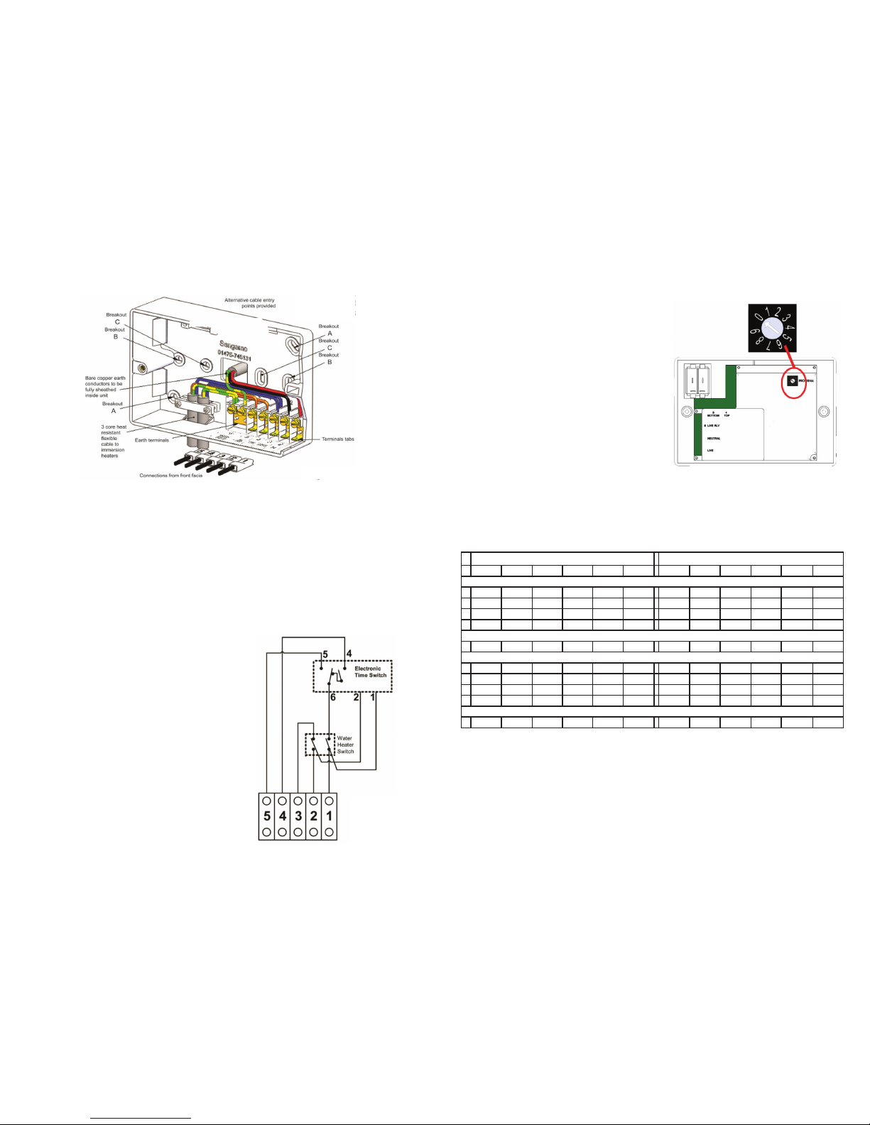
WIRING
Use a three core heat resistant cable with a minimum
conductor size of 1.5mm connection to a 3kW heater.
Connect the incoming wires to the terminal block as
follows:
1. Live In
2. Neutral In
3. Heater Neutral
4. Boost Load
5. O Peak Load
Link terminals 4 & 5 if using a single immersion heater.
The Powersaver Dual Flexi should be removed from the mounting box by unscrewing the 2
captive pattress screws.
Conduit box mounting - Use either holes marked ‘C’ to secure to a single gang box or the two
holes marked ‘B’ for a double gang box. Cable entry is through the rear breakout.
Surface mounting - Use the two holes marked ‘A’. Cable entry is through the most appropriate cut
out.
Remove the appropriate cable entry cut outs before xing the box, where possible drill the box to
provide a close tting entry for cables, taking care to remove sharp edges.
Ensure outgoing cables to the immersion heaters are securely clamped in the box. All surface
wiring adjacent to the box should also be clamped appropriately or trunking used.
MOUNTING COMMISIONING
When the product leaves the factory the installer
switch is set at program 0. The product settings may
be reviewed/entered when not connected to a power
supply. Pressing ‘-’ or ‘+’ buttons will activate the
display and enable the review/settings to be made.
NB: to conserve battery power, the display will turn
o aer approx 30 sec. when o power.
See user instructions for operating details.
The user may need to check with their electricity
supplier to conrm the o-peak electricity times used
in that area & whether these times change between
Winter (GMT) & Summer (GMT+1).
It is the responsibility of the installer to ensure
that the correct setting is applied for the appropriate electricity tari.
NB: A program can comprise of 1, 2 or 3 on/o programs depending on the tari selected.
Some program times remain the same and some change between Winter & Summer. For
greater exibility, program times are adjustable within the preset limits. The clock time will
automatically adjust no matter which program is selected.
To complete installation, take the front panel and push connectors numbered 1-5 into the
corresponding terminal in the mounting base. Carefully present the front panel to the mounting
box and secure with xing screws. Ensure no wiring becomes trapped or damaged in the process.
Switch on the mains supply and put the rocker switch in the TIMED position.
Winter (GMT) Summer (GMT+1)
ON OFF ON OFF ON OFF ON OFF ON OFF ON OFF
Economy 7
012:30am 6:30am 1:30am 7:30am
111:30pm 7:30am 12:30am 8:30am
210:00pm 8:30am 11:00pm 9:30am
310:30pm 12:30am 2:30am 7:30am 11:30pm 1:30am 3:30am 8:30am
Eco 20:20
49:00pm 7:00am 10:00pm 8:00am
Economy 10
512:00am 7:00am 2:00pm 5:00pm 7:00pm 10:00pm 12:00am 7:00am 2:00pm 5:00pm 7:00pm 10:00pm
62:00am 7:00am 2:00pm 4:00pm 7:00pm 10:00pm 2:00am 7:00am 2:00pm 4:00pm 7:00pm 10:00pm
712:00am 5:00am 1:00pm 4:00pm 8:00pm 10:00pm 12:00am 5:00am 1:00pm 4:00pm 8:00pm 10:00pm
84:30am 7:30am 1:30pm 4:30pm 8:30pm 12:30am 4:30am 7:30am 1:30pm 4:30pm 8:30pm 12:30am
This preset MUST be adjusted or the unit will remain permanently ON
912:00am 8:00am 8:00am 4:00pm 4:00pm 12:00am 12:00am 8:00am 8:00am 4:00pm 4:00pm 12:00am