SANO LIFTKAR HD User manual

LIFTKAR HD
HD UNI / HD FOLD / HD DOLLY / HD FOLD DOLLY
INSTRUCTION MANUAL
English

Liftkar HD I 2
INTRODUCTION 3 .....................................................................................................................................................................
1 SAFETY GUIDELINES / TECHNICAL DATA 4 ........................................................................................................................
1.1 General safety guidelines 4 ............................................................................................................................................
1.2 Built-in safety features (depending on model) 4 ............................................................................................................
1.3 Technical data LIFTKAR HD models 6 .............................................................................................................................
1.4 Technical data of quick-change battery unit 6 ...............................................................................................................
2 CONTROL FEATURES 7 .........................................................................................................................................................
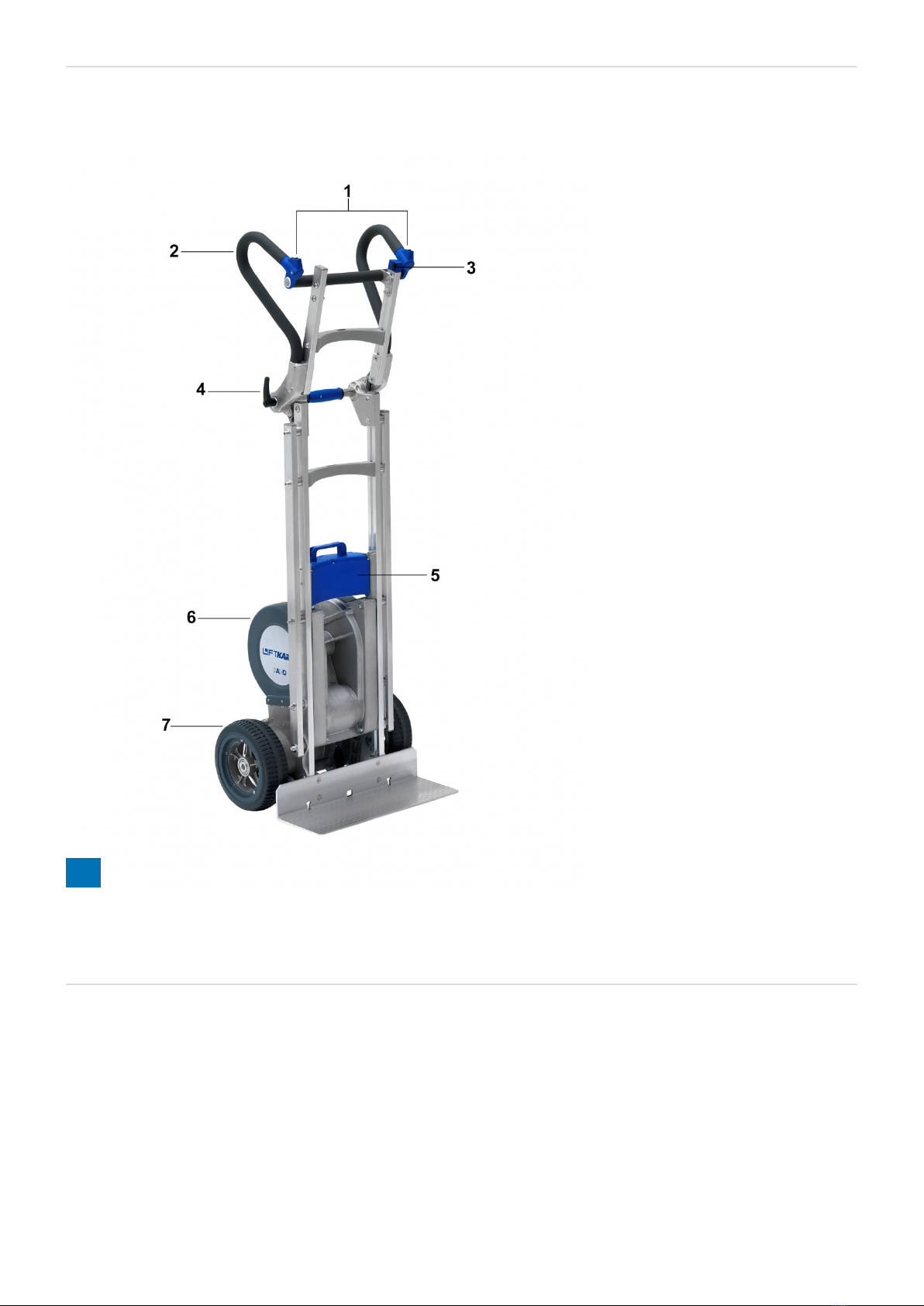
2.1 UNI model 7 ...................................................................................................................................................................
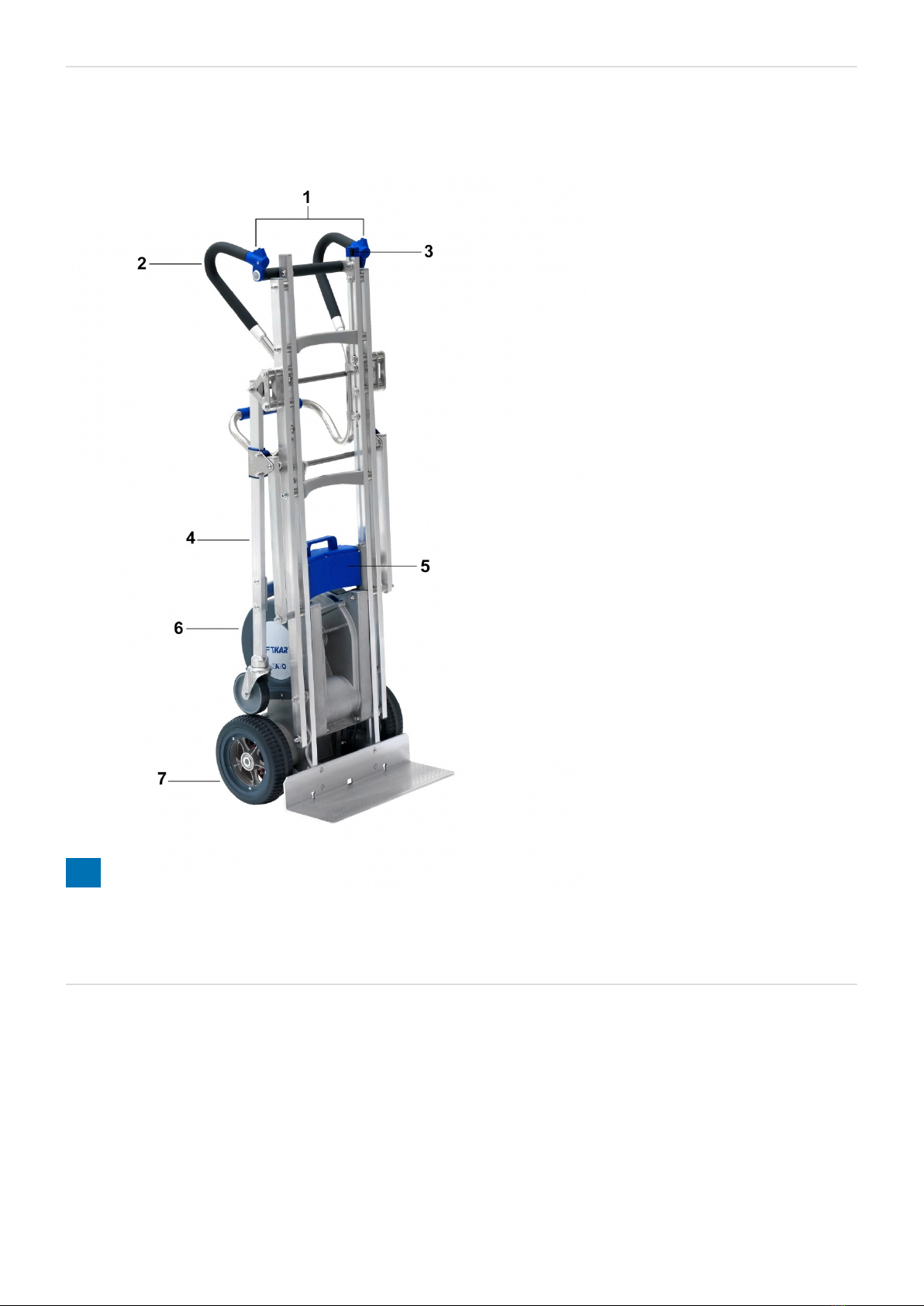
2.2 Fold model 8 ..................................................................................................................................................................
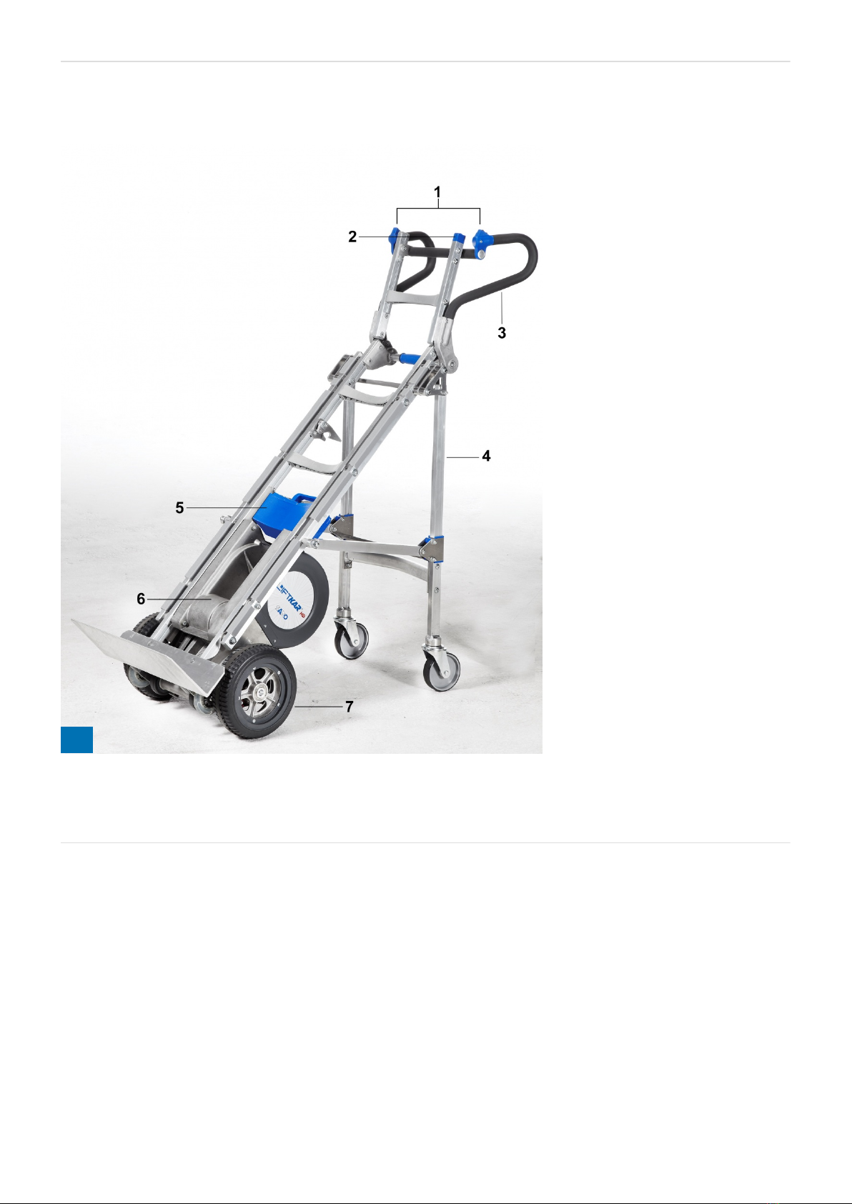
2.3 Dolly model 9 .................................................................................................................................................................
2.4 Fold Dolly model 10 .......................................................................................................................................................
2.5 Control unit 11 ...............................................................................................................................................................
2.6 UP/DOWN switch on handlebar 12 .................................................................................................................................
2.7 Main switch 12 ...............................................................................................................................................................
2.8 Switching off 13 .............................................................................................................................................................
3 FITTING AND REMOVING QUICK-CHANGE BATTERY PACK 14 ........................................................................................
3.1 Fitting battery pack 14 ...................................................................................................................................................
3.2 Removing battery pack 14 .............................................................................................................................................
4 OPERATION 15 ......................................................................................................................................................................
4.1 Climbing UP stairs 15 .....................................................................................................................................................
4.2 Climbing DOWN stairs 15 ...............................................................................................................................................
5 HOW THE LIFTKAR EDGE BRAKING SYSTEM WORKS 16 .................................................................................................
5.1 Enabling the system 16 ..................................................................................................................................................
5.2 Deactivating and blocking the edge braking system 17 ................................................................................................
5.3 Automatic switch-off after extended period of no operation 17 .....................................................................................
5.4 How to test the step edge braking system 18 ................................................................................................................
6 CHARGING THE QUICK-CHANGE BATTERY PACK 18 ........................................................................................................
6.1 Charger unit 19 ..............................................................................................................................................................
7 ACCESSORIES AND OPTIONS 20 .........................................................................................................................................
8 DISPOSAL 20 .........................................................................................................................................................................
9 WARRANTY AND PRODUCT LIABILITY 21 ..........................................................................................................................
9.1 Warranty 21 ...................................................................................................................................................................
9.2 Liability 21 .....................................................................................................................................................................
10 CE DECLARATION OF CONFORMITY / PATENT REGISTERED 22 ...................................................................................
NOTES 23 ..................................................................................................................................................................................
CONTACT 24 ..............................................................................................................................................................................

Liftkar HD I 3
INTRODUCTION
CONGRATULATIONS!
WE WOULD LIKE TO CONGRATULATE YOU ON THE PURCHASE OF YOUR POWERED STAIRCLIMBER
TRUCK TYPE LIFTKAR HD!
You have chosen a unit using the very latest stairclimber technology for negotiating different types of steps and
stairs safely and efficiently.
Development of the LIFTKAR HD focussed especially on user safety and user friendliness.
Key features:
Two UP / DOWN switches - one on the left and one on the right of the handle unit - for perfect user comfort.
Ideal for both left- and right-handed operators.
Automatic braking system that ensures the main wheels stop reliably at the edge of each step from the moment
the unit is switched on.
Optimum protection against impact to the support wheels thanks to a lubricated mechanical clutch.
Additional electronic protection prevents damage due to overloading.
2 climbing speeds and two operating modes (single-step mode and continuous mode) to perfectly match your
operating style.
Excellent performance on spiral staircases.
In order to update you about product news as well as technical changes (e.g. options, accessories) we ask you
to register your product online.
https://www.sano-stairclimbers.com/product-registration

Liftkar HD I 4
1 SAFETY GUIDELINES / TECHNICAL DATA
1.1 GENERAL SAFETY GUIDELINES
Make sure nobody is located underneath the load.
Always secure the load with the safety belt included.
Always wear non-slip shoes. Some steps may be very smooth.
Always wear shoes with steel toecaps.
The Liftkar may only be operated by trained personnel.
Never reach into the unit's transport mechanism with your hands.
Plan each journey on the stairs according to the current situation before you start.
Always remove the battery pack before stowing the LIFTKAR. Firstly so the LIFTKAR cannot be switched on
inadvertently during transport and secondly because the LIFTKAR is 4 kg lighter without the battery pack.
1.2 BUILT-IN SAFETY FEATURES (DEPENDING ON MODEL)
Fold model:
Each time before you use the stairclimber, make sure that the quick release lever (figure 2, chapter 2.2) on
the handles is tightened properly. It must be possible to tilt the load from the standing position without
assistance. The position of the handle section in relation to the frame must not be altered.
Dolly model:
Figure A shows the protection system when retracted.
Figure B shows the protection system when extended. The sliding arm must be at right-angles to the
protection system.
A: Sliding Arm - B: Dolly-System A: Sliding Arm - B: Dolly-System
Each time before starting up the stairclimber, make sure that the protection system is properly folded away
(retracted, figure D).
A B

Liftkar HD I 5
Folding away Support system retracted
IMPORTANT
Do not use the protection system in the extended position while operating the stairclimber on
stairs.
CD

Liftkar HD I 6
1.3 TECHNICAL DATA LIFTKAR HD MODELS
Model Uni Fold Dolly
Load capacity 360 kg 330 kg 220 kg
Maximum climbing speed with full load (steps/min) 9-10 9-10 14-15
Maximum step height 210 mm 210 mm 210 mm
Model Weight (incl. battery pack)
HD UNI 38 kg
HD Fold 39 kg
HD Dolly 44 kg
HD Fold Dolly 45 kg
1.4 TECHNICAL DATA OF QUICK-CHANGE BATTERY UNIT
Fuse: internal blow-out fuse (30 Amp)
Charging contact: DC Jack dia. 2,1 x 9,5
Weight of battery: 4 kg
Capacity: 5 Ah
Voltage: 24 VDC (2x 12 VDC - 5 Ah)
Type of battery: maintenance-free, leak-safe lead gel cell (approved by DOT and IATA for air freight)

Liftkar HD I 7
2 CONTROL FEATURES
2.1 UNI MODEL
1: UP/DOWN switches - 2: Handles - 3: Control unit - 4: Quick-change battery pack - 5: Climbing mechanism - 6:
Main wheels
1

Liftkar HD I 8
2.2 FOLD MODEL
1: UP/DOWN switches - 2: Handles - 3: Control unit - 4: Quick release - 5: Quick-change battery pack - 6:
Climbing mechanism - 7: Main wheels
2

Liftkar HD I 9
2.3 DOLLY MODEL
1: UP/DOWN switches - 2: Handles - 3: Control unit - 4: Dolly-System - 5: Quick-change battery pack - 6:
Climbing mechanism - 7: Main wheels
3

Liftkar HD I 10
2.4 FOLD DOLLY MODEL
1: UP/DOWN switches - 2: Control unit - 3: Handles - 4: Dolly-System - 5: Quick-change battery pack - 6:
Climbing mechanism - 7: Main wheels
4

Liftkar HD I 11
2.5 CONTROL UNIT
1: LED - 2: ON/OFF multifunction key P - 3: Speed selector
2.5.1 ON/OFF AND SINGLE-STEP/CONTINUOUS MODE MULTI-FUNCTION
SWITCH (P)
The LIFTKAR is ready for operation after the battery pack has been switched on (ON/OFF switch on power
pack) and you briefly press button P. This is confirmed by the green LED display on the control unit going on.
The LIFTKAR is in Single- step mode.
If you briefly press button "P" again the unit switches to Continuous mode. This is signalled by the LED
flashing green.
Pressing the button for longer than 3 seconds switches the LIFTKAR off.
2.5.2 LED DISPLAY
Green light on: LIFTKAR is in Single-step mode. Pressing one of the UP/DOWN switches (see figure 6,
chapter 2.6) starts the LIFTKAR moving. The unit switches off automatically after one climbing cycle has been
completed (raising or lowering the LIFTKAR one step).
Flashing green: The LIFTKAR is in Continuous mode. For users with plenty of practice. The LIFTKAR starts
climbing when the UP/DOWN switch is pressed and doesn't stop until the UP/DOWN switch is released.
Flashing red: The LIFTKAR is overloaded. (The LED flashes for approx. 3 seconds and then goes out – see
also Operation section 4.2.1.)
Alternating red and green: the battery pack is running low and urgently needs to be recharged. The
stairclimber will certainly manage another flight of stairs, but it is recommended that you move down stairs
and either change the battery pack or recharge it with the quick charger supplied. In addition, an integrated
beeper provides an acoustic signal to indicate that the battery charge is low. The beep frequency increases
the lower the battery level.
5

Liftkar HD I 12
IMPORTANT
Keep pressing the UP/DOWN switch in Single-step mode until the LIFTKAR reaches the next step
and stops automatically. Then release the switch. Pressing the switch again starts the LIFTKAR on
its next movement cycle. If the switch is released by mistake during a cycle, simply press the
UP/DOWN button again to continue the movement. The Liftkar continues operating until it reaches
the end of the cycle and stops automatically. Releasing the button and pressing it again starts the
next climbing cycle.
2.5.3 SPEED SWITCH
Use the speed switch to select higher or lower climbing speeds (figure 5).
The lower speed or single-step mode is recommended for beginners, heavy loads and difficult situations.
2.6 UP/DOWN SWITCH ON HANDLEBAR
With an UP/DOWN switch located both on the left and right of the handlebar (figure 6), this unit is ideal for both
left- and right-handed operators.
A: UP/DOWN switch
B: DOWN - C: UP
2.7 MAIN SWITCH
The main switch is located on the quick-change battery pack. The power supply to the unit can be switched off
safely using the main switch (figure E).
6

Liftkar HD I 13
2.8 SWITCHING OFF
The unit can be switched off in the following ways:
Removing the quick-change battery pack (see section 3).
Using the main switch on the quick-change battery pack (see figure E).
Pressing multi-function switch P for longer than 3 seconds.
Leaving the unit for a period of time: The LIFTKAR switches off automatically after 10 minutes.
Using the main switch or removing the battery pack provides a higher level of safety than
switching off using switch P or leaving the unit to switch off automatically because switch P could
easily be actuated inadvertently, causing the machine to switch on.
Always switch off the main switch on the battery pack before stowing the unit away.
E

Liftkar HD I 14
3 FITTING AND REMOVING QUICK-CHANGE
BATTERY PACK
3.1 FITTING BATTERY PACK
First position corner A in hook B.
Gently press battery pack forwards swiftly. The battery pack clicks into place.
Set switch on battery pack to ON and your LIFTKAR is ready for operation.
C: Latches
3.2 REMOVING BATTERY PACK
Lift the battery pack sharply upwards. It then disengages automatically.

Liftkar HD I 15
4 OPERATION
4.1 CLIMBING UP STAIRS
Fit battery pack, switch main switch to ON, press briefly on multi-function switch P until the LED display goes
permanently green (Single-step mode, refer to section 2.5.1.), or flashes green (Continuous mode).
The LIFTKAR is now ready for operation.
Pressing one of the UP/DOWN switches Q (figure 6, left and right of handlebar, arrow upwards points towards
operator) starts moving the lift arm with the support wheels and lifts the LIFTKAR onto the next step. The cycle
is repeated until the switch is released (Continuous mode, LED flashes green). In Single-step mode the LIFTKAR
stops when the main wheels reach the next step.
IMPORTANT
As soon as the main wheels have "landed" on the next step, always draw the unit away from the
edge of the step and contacts the step above.
4.2 CLIMBING DOWN STAIRS
Fit battery pack, switch main switch to ON, press briefly on multi-function switch P until the LED display goes
permanently green (Single-step mode, refer to section 2.5.1.), or flashes green (Continuous mode).
The LIFTKAR is now ready for operation.
Pressing one of the UP/DOWN switches Q (figure 6, left and right of handlebar, arrow downwards points away
from operator) starts moving the lift arm with the support wheels and lowers the LIFTKAR onto the next step.
The cycle is repeated until the switch is released (Continuous mode, LED flashes green). In Single-step mode the
LIFTKAR stops when the main wheels reach the next step.
IMPORTANT
As soon as the main wheels have landed on the step, always push the Liftkar to the edge of the
next step. The brake wheels stop the Liftkar reliably on the edge of the step.

Liftkar HD I 16
4.2.1 OVERLOAD
If the unit is overloaded the drive motor stops and the LED flashes red for 3 seconds before going out. The unit
has to be switched on again.
If the power of the battery pack is running out then the overload signal will be displayed even on
loads below the specified capacity.
4.2.2 THE LIFTKAR IS NOT A RUBBER MAT!
Never throw a load onto the LIFTKAR! We recommend that this kind of loading method is avoided because it
causes higher wear and may damage the LIFTKAR control unit as a result of vibrations.
4.2.3 DO NOT RIDE OVER KERBS AT AN ANGLE
Always ride over kerbs or similar edges with both wheels contacting the edge at the same time. This will
prevent damage to the drive unit.
4.2.4 OPERATION ON SPIRAL STAIRCASES
Please observe the following points when operating the stairclimber on spiral staircases:
The LIFTKAR moves inwards when climbing up, so:
For climbing UP start on the outside of the staircase.
The LIFTKAR moves outwards when going down, so:
For climbing DOWN start on the inside.
If you do start moving too close to the banisters/wall then shift the unit to the side by reversing (on a landing or
wider step if possible) and start again at a tighter angle.
5 HOW THE LIFTKAR EDGE BRAKING SYSTEM
WORKS
5.1 ENABLING THE SYSTEM
The edge braking system is enabled automatically as soon as the LIFTKAR is switched on using the "ON/OFF"
switch (figure 5). This ensures that the brake blocks inside the rims of the main wheels block the main wheels as
soon as the unit approaches the edge of a step. The brakes are released mechanically as soon as the main
wheels contact the next step. The brake system remains active and engages automatically when the main
wheels approach the edge of the next step.

Liftkar HD I 17
5.2 DEACTIVATING AND BLOCKING THE EDGE BRAKING
SYSTEM
The edge braking system is blocked if the LIFTKAR is switched off using the "ON/OFF" switch
(figure 5 - LED is no longer green or flashing) and the unit is parked on its toe plate.
The LIFTKAR then no longer stops automatically at the edge of a step.
NOTE
It is a good idea to deactivate the brake system on uneven ground because bumps or dips in the
ground would otherwise cause the main wheels to be stopped if one of both of the edge brakes
were activated.
IMPORTANT
Make sure that the system is switched on again before starting each movement downwards to the
next step.
This is indicated by the LED changing to green or flashing green (see section 2.5.1. for operating
modes). Only then is the edge braking system enabled.
5.3 AUTOMATIC SWITCH-OFF AFTER EXTENDED PERIOD OF
NO OPERATION
Please note that the LIFTKAR switches off automatically to save the battery pack after approx. 10 min without
the UP/DOWN switch being pressed). The edge braking system is also deactivated (providing the unit is parked
on the toe plate).
IMPORTANT
Always check the status of the LED when starting moving again after a pause (LED must be green
or flashing green). Only then is the edge braking system engaged.
NOTE
Do I have to make sure the edge braking system is activated on every step? No, you only have to
approach the edge of the step.
Hand width rule: It is enough to position the LIFTKAR roughly one hand width away from the
edge of the step (distance between point main wheels contact step and edge of step, i.e. approx.
7 – 8 cm). Now you can start the next lifting cycle and the LIFTKAR will land safely on the next
step.

Liftkar HD I 18
5.4 HOW TO TEST THE STEP EDGE BRAKING SYSTEM
Correct functioning of the step edge braking system is essential for safe operation of the stairclimber.
It is therefore essential that you check the function of the step edge braking system each time before you use
the stairclimber.
Test the step edge braking system (without load):
Tilt the LIFTKAR back until it is at an angle of approx.1.
45° (figure 7).
Switch on the stairclimber by pressing the main switch.2.
When you push the LIFTKAR forwards the step edge3.
braking system should engage to brake/stop the main
wheels of the stairclimber.
If the brakes do not engage uniformly (uneven braking4.
on left and right wheel), do not use the LIFTKAR for
climbing stairs until it has been checked by an
authorised Sano technician.
6 CHARGING THE QUICK-CHANGE BATTERY PACK
The lead gel cells inside the battery pack are maintenance-free, gas-tight and rechargeable. Their service life
depends largely on the charging/discharging cycles. For example, it is possible to partially discharge lead
batteries 1000 times, drawing more than 200 times the full capacity of the battery, providing the battery is
never fully discharged.
Avoid discharging the battery completely. Charge the battery pack as often as possible.
Lead batteries are susceptible to self-discharging. It is therefore necessary to recharge the quick-change
battery pack after 3 weeks, even if it has not been in use.
The charger unit supplied switches over automatically to compensation charging so it is not possible to over-
charge the battery.
Do not leave the quick-change battery pack discharged or half discharged. Always recharge the battery
immediately.
If the batteries should become damaged it is possible to have them replaced in any reputable mechanical
workshop. The old lead batteries are fully recyclable and are not to be disposed of.
The ideal temperature for charging is between 20 and 25° C. Temperatures that are too cold or too hot will
affect the battery's capacity.
7

Liftkar HD I 19
If the battery pack is not fully charged, or it looses its charge suddenly, not only will the speed of
the LIFTKAR be slower, but its capacity is reduced as well. This means that overload may be
displayed even with a relatively light load. See section 4.2.1.
6.1 CHARGER UNIT
The battery charger supplied is extremely powerful. An LED display gives
a clear indication of charging status. The charge indicator gives you an
idea whether the battery pack is fully charged or not. It is worth checking
that the battery pack is fully charged before using the Liftkar.
The charge status is displayed as follows by a LED:
If the LED is lit continuous red the battery pack is being charged.
If the LED is lit continuous green the battery pack is fully charged. The charger can be left connected to the
batteries after full charge (green light), without harming the batteries. The charger uses minimum power in
this stand-by mode, (after battery is fully charged), maintains the batteries at full charge and extends battery
life. This is accomplished with electronic circuitry that controls and regulates the amount of charging current
that is sent from the charger to the battery being charged.
6.1.1 TECHNICAL DATA
Mains voltage supply (50/60 Hz, 0,7A): 100-240 V AC
Nominal rating (input): 24 W
Charging voltage: 24 V DC
Theoretical charging current: 1,0
Protection class: IPX4
Safety approval: UL, cUL, CE
6.1.2 SAFETY GUIDELINES
Please note the following:
Protect against damp
Only charge in a well ventilated room
Do not pull the plug out of the socket by its cord
Do not operate charger with damaged cord or plug - replace immediately!

Liftkar HD I 20
6.1.3 USE ONLY FOR THE PURPOSE INTENDED
The charger unit is designed exclusively for charging lead-acid batteries containing liquid, gel-type and
fabric-type electrolyte
It is not permissible to charge NiCd or NiMH batteries or primary cells.
7 ACCESSORIES AND OPTIONS
A full range of accessories and options is available. The list includes various sizes of toe plate, add-on toe plates
with castors, safety belts, vehicle chargers for charging in transit, and much more. Please ask your dealer.
8 DISPOSAL
Liftkar HD stairclimbers are durable products. At the end of their useful life the stairclimber components and
charger should be disposed of properly. Make sure the materials are separated carefully for disposal in line with
the material codes relating to each component.
The stairclimber does not contain any hazardous materials and is fully recycling-compatible. The printed circuit
boards and the rechargeable battery must be disposed of using a suitable recycling process.
Do not simply dispose of the battery pack in a household dustbin, however. If there are any further questions,
please ask your specialist dealer.
Sano can organise professional disposal of the whole stairclimber unit, against payment, if required.
This manual suits for next models
4
Table of contents