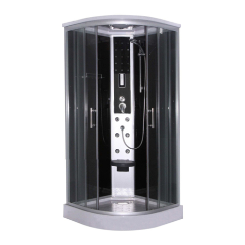
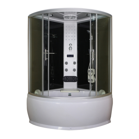
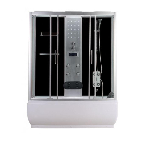
Sanotechnik TR150 User guide

TR150-TR170
D – Montageanleitung
E – Mounting Instruction
HR – Uputi za upotrebu
SLO – Navodlilo za monta o kadi
HU – Útmutató a zuhanykabin beszereléséhez
RO – Instructiuni de montaj
CZ – Návod k montá I vany
SK – Návod na montáž
TR – Kullanma Klavuzu
Sanotechnik Handelsgesellschaft m.b.H.
Industriestraße 5
A-2752 Wöllersdorf
Tel.: 0043/2622/421 93-0
Fax. 0043/2622/421 93-6
www.sanotechnik.com
Sanotechnik RUMÄNIEN S.R.L SANOTECHNIK d.o.o SANOTECHNIK Hungária Kft. SANOTECHNIK Maurod s.r.o. FORMATIC Ltd.
ROMANIA SLOVENIA HUNGARY SLOWAKIA+CZECHIA BULGARIA
Tancabesti, DN 1, KM 26,5 Stritarjeva ulica 24 Nagytétényi út 112 Sládkovièova 69 3, Georgi Benev St.
Com. Snagov, jud. Ilfov SI-2000 Maribor H-1222 Budapest SK-953 01 Zlaté Moravce BG-4003 Plovdiv
Tel.: +40 21 350 13 43 Tel.: +386 2/421 33 50 Tel.: +36 1/424 06 70 Tel.: +421/376 426 245 P.O. BOX 85
Fax: +40 21 350 13 44 Fax: +386 2/421 33 58 Fax: +36 1/424 06 79 Fax : +421/376 426 246 Tel.: +359 32/9611 01
www.sanotechnik.com www.sanotechnik.com www.sanotechnik.com www.sanotechnik.com [email protected]
03_2010

Packliste – Packing list - A csomag tartalma – Seznam ČÁSTÍ BALENÍ - COMPONENTE –
Lista sestavnih delov - Lista sastavnih djelova
Deutsch English Magyar Czech RomânăSlovensko Hrvatski Slovensky Turkey
1 15 Schrauben
ST3.5*11
Screw
ST3.5*11
Csavarok
ST3.5*11
šrouby
ST3.5*11
Şuruburi
ST3.5*11
Vijaki
ST3.5*11
Vijci
ST3.5*11
Skrutky
ST3.5*11
Vida
ST3.5*11
2 1 Dach Top cover Tetőstřecha Capac Zgornji del Gornji dio Horná časťTavan
3 1 Ventilator Ventilator Ventillátor ventilátor Ventilator Ventilator Ventilator Ventilátor Vantilatör
4 1 Kopfbrause Head
shower Fejzuhany sprcha
hlavy
Cap
dispersor
dus
naglavni
tuš
tuš iznad
glave
Hlava
sprchy
Tepe Duşu
5 1 Licht Top light Világítás osvětlení Iluminare LučSvjetlo Svetlo
Tepe Işığı
6 1 Lautsprecher loudspeaker Hangszóró reproduktor difuzor zvočnik zvučnik reproduktor Hoparlör
7 1 Führungsschiene
oben
Bend rail
top
Felső
vezetősín
Vodící
oblouk
horní
Profil
ghidaj sus
Vodilo -
zgoraj
Horná
vodiacia
lišta
Üst Profil
8 1 Rückwand Back wall Hátfal zadní stěna Partea
din spate
hrbtni
panel
zadnja
panel
Zadná
stena
Arka
Cam Panel
9 22 Schrauben
ST3.5*13
Screw
ST3.5*13
Csavarok
ST3.5*13
šrouby
ST3.5*13
Şuruburi
ST3.5*13
Vijaki
ST3.5*13
Vijci
ST3.5*13
Skrutky
ST3.5*13
Vida
ST3.5*13
10 1 Ablage Shelf Piperepolc polička Poliţă Polička Polica
Odkladací
priestor
Raf
11 1 Massagepaneel Back wall Hátfal zadní stěna Partea
din spate
hrbtni
panel
zadnja
panel
Zadná
stena
Masaj
Paneli
12 1 Kontrollelement Control
panel Kezelőpanel kontrolní
panel
Panou de
comanda
Kontrolni
elem.
Kontrolni
elem.
Kontrolný
element
Kontrol
Paneli
Packing1 22,35,29
Packing2 11,17,18,22,27,28
,29,32
Packing3 8,13,15,16
Packing4
1,2,3,4,5,6,7,
9,10, 12, 14,
19,20,21,
23,24,25,26,
30,31,
33,34,36,37

13 1 Rückwand Back wall Hátfal zadní stěna Partea
din spate
hrbtni
panel
zadnja
panel
Zadná
stena
Arka Cam
Panel
14 8 Schrauben
ST3.8*2.5
Screw
ST3.8*2.55
Csavarok
ST3.8*2.5
šrouby
ST3.8*2.5
Şuruburi
ST3.8*2.5
Vijaki
ST3.8*2.5
Vijci
ST3.8*2.5
Skrutky
ST3.8*2.5
Vida
ST3.8*2.55
15 4 Führungsschienen
kurz
Bend rails
short
Vezetősín,
rövid
Vodící profil
krátky
Profile
ghidaj
scurte
Vodila -
kratka
Vodiace
lišty krátke
Yan Profil
16 2 Seitenwand Side wall Oldalfal boční stěna Perete
lateral
stranski
panel
panel sa
strane
Bočná
stena
Yan Cam
17 2 Aluminium Profil Aluminium
rail Alu profil ukončovací
profil skla
Profil
aluminiu ALU-profil ALU-profil Tesnenie Arka Dikey
Profil
18 4 Innenprofile
Fixed
profiles
(inside)
Belsőprofil Venkovní
profil
Profil fix
(interior)
Fiksni profili
(znotraj) Vnútorné
profily
Ön Dikey
Profil
19 1 Handtuchhalter Towel rail Törölközőtartó držák
ručníku
Suport
prosop
Držalo
brisač
Nosač
ručnika
Držiak na
uterák
Havlu Barı
20 12 Schrauben M4*20 Screw
M4*20
Csavarok
M4*20
šrouby
M4*20 Şuruburi
M4*20
Vijaki
M4x20
Vijci
M4x20
Skrutky
M4*20
Vida
M4*20
21 1 Badewanne bathtub Kád
sprchová
vanička
Cadita
dus tuš kad tuš kada Sprchová
vanička
Küvet
22 2 Wandprofile fix profiles Sarokprofil Rohový
profil
Profil
colt Kotni profili Rohové
profily
Ön dikey
Profil
23 1 Handbrause Hand
shower Kézi zuhany ruční
sprcha Dispersor Tuš ročka Tuš ručica Ručná
sprcha
El Duşu
24 1 Brausestange Sliding bar Zuhanysín Sprchová
tyč
Suport
dus
Vodilo za
prho
volilica za
tuš
Tyčna
sprchu
KapıCamı
25 2 Brauseschlauch Shower
hose
Zuhany
gégecső
sprchová
hadice
Furtun
dus tuš cev tuš cijev Sprchová
hadica
El Duşu
Hortumu
26 1 Fußmassage foot
massage Lábmasszírozó masaz
nohou nasaj talpi Masaza
stopal
Masaza
stopala Masáž nôh Ayak
Masajı
27 1 Armatur Faucet Csaptelep armatura Baterie armatura miješalica Batéria Musluk
28 4 Düsen Jets Fúvókák trysky Duze Šob Mlaznica Trysky Masaj
Jetleri
29 2 Glasfixteile Fix doors Fix üvegfal pevná část
koutu Usa fixa Stekleni
fiksni panel
Stakleni
fiksni
panel
Sklenené
pevné
dielcekútu
Sabit ön
cam
30 2 Glasfixteil
gebogen
Fixglaspart
Bend
Fix üvegfal,
íves
Pevný díl
ohnutý
Parte fixa
de sticla
Fiksni
stekleni del
- upognjen
Pevný
sklenený
diel,
zahnutý
Sabit Cam
Contası
31 4 T Dichtung "T" gasket "T"-tömítés "T" těsnění Cheder T T-tesnilo T-brtvilo "T"
tesnenie
T conta
32 2 Frontprofile Front Fixed
profiles Frontprofil Čelní profil Profil fata
fix
Fiksni profili
- sprednji Čelné
profily
Ön Sabit
Profil
33 2 Griffe Handles Fogantyú úchytky Mânere Ročaji Rukohvati Úchytky
KapıKulbu
34 8 Rollen Sliding
wheel Görgők pojezdy Role Koleščki Kotačići Kolieska Kapı
Tekerleği
35 2 Schiebetüren Sliding doors Tolóajtó posuvné
dveře
Usi
culisante Drsna vrata Klizna
vrata
Posuvné
dvere
KapıCamı
36 4 Schrauben ST4*10 Screw
ST4*10
Csavarok
ST4*10
šrouby
ST4*10 Şuruburi
ST4*10
Vijaki
ST4*10
Vijci
ST4*10
Skrutky
ST4*10
Vida
ST4*10
37 1 Führungsschiene
unten
Bend rails
bottom Alsó vezetősín
Vodící
oblouk
spodní
Profil
ghidaj jos
Vodilo -
spodaj
Spodná
vodiaca
lišta
Yatay
Profil

DEUTSCH – DEUTSCH – DEUTSCH – DEUTSCH – DEUTSCH – DEUTSCH
INHALTSVERZEICHNIS :
MONTAGE UND BEDIENUNGSANLEITUNG Seite
1) Vorwort................................................................................1
2) Wasser- u. Elektroinstallation..............................................1
3) Garantiebestimmungen.......................................................1
4) Nutzungsbestimmungen und Pflege...................................2
5) Montage ............................................................................3-9
6) Anschlüsse Wasserleitung..................................................10
7) Anschlüsse Elektronik.........................................................11
8) Bedienelement Radio ........................................................12
8)Betriebsanleitung für Radio..................................................12
WICHTIG ! WICHTIG ! WICHTIG ! WICHTIG !
Es muss von der Kundenseite immer gewährleistet sein, dass die Komplettduschkabine so montiert ist, dass für
eventuelle Wartungsarbeiten oder Reparaturarbeiten die Komplettduschkabine frei zugänglich ist. Die
Komplettduschkabine darf nur in einem Raum aufgestellt bzw montiert werden der zur Gänze verfließt ist. Weiters
muss in diesem Raum ein Bodensiphon vorhanden sein.
Die mitgelieferten Stahl-Flex-Schläuche (Kalt- Warmwasseranschluss) dienen nur für TESTZWECKE!
Es müssen die technischen Vorraussetzungen vor Montage kontrolliert werden wie zB Wasserdruck 1-3 bar,
Kalkhaltigkeit max 8 dh usw.

Vorwort
1. Bevor Sie die Duschkabine auspacken überprüfen Sie die Verpackung auf eventuelle Schäden. Spätere
Reklamationen werden nicht anerkannt. Vor der Montage sind auch alle Teile auf Schäden und auf Vollständigkeit zu
überprüfen. Bei Problemen kontaktieren Sie den Verkäufer bzw. uns zeitgerecht und Sie werden eine zufriedenstellende
Antwort bekommen.
2. Für die Montage ist folgendes Werkzeug erforderlich: Bohrmaschine, Kreuzschraubenzieher, Wasserwaage,
Maßband, Stift, Ringgabelschlüssel.
3. Bei geprägtem Glas oder Milchglas ist zu beachten, dass die glatte Seite nach Innen montiert wird.
4. Es wird jede Duschkabine werkseitig zu Testzwecken montiert, angeschlossen, getestet und wieder verpackt.
5. Die Brausetasse aufstellen und mittels verstellbarer Füße, so einstellen, dass kein Wasser in der Brausetasse bleibt.
ACHTUNG: unbedingt testen. Spätere Reklamationen sind ausgeschlossen.
6. Die Montage darf nur durch autoritäre Fachfirmen (z.B. Installateur) durchgeführt werden, ansonsten erlischt die
Garantie. (Siehe auch Hinweis für Anschluss von Wasser und Strom)
7. Es ist die beiliegende Aufbauanleitung einzuhalten, sowie müssen alle Teile zusätzlich gegeneinander mit
Sanitärsilikon abgedichtet werden (Silikon Dichtheitsprobe). Weiters müssen alle Schrauben, Schlauchklemmen, usw.
auf ihre Festigkeit und Dichtheit überprüft werden. Es könnte sich durch den Transport etwas gelockert haben.
INSTALLATIONS – WARTUNGS – GARANTIE – SICHERHEITS – NUTZUNGS BESTIMMUNGEN
TECHNISCHE DATEN:Anschluss 220 V / 50 Hz, Steuerung 12 V
Wasserdruck 1 – 3 bar, max. 60° WW, max. 9° DH
1. WASSERINSTALLATION:
(Bauseits) Der Anschluss darf nur von einem behördlich konzessionierten Installationsunternehmen durchgeführt werden. Die
Installationsvorschriften der örtlichen Wasserversorgungsunternehmen sowie die Bestimmungen der DIN 1988 sind strengstens zu
beachten. Für den Abwasseranschluss ist ein Geruchsverschluss vorzusehen.
ACHTUNG: Keine starren Rohrverbindungen zwischen Fertigdusche und Wasserleitung – Bruchgefahr !!! Diese Leitung muss
durch einen Rohrunterbrecher Bauart A2 nach DIN 1988 gesichert sein. Die Anschlüsse müssen flexibel sein, sodass eine
ungehinderte Wartung oder Service jederzeit möglich ist.
Die Wassertemperatur des Wassers, welches über die Armaturen und Brausen einfließt darf max. 60°C betragen. Der
Wasserdruck darf max. 4 bar betragen.
Generell sind für die Wasserinstallation alle gesetzlichen Vorschriften einzuhalten.
2. WASSERABLAUF: (Bauseits) ∅40mm (∅50mm)
Es muss ein flexibles-ausziehbares Zwischenstück (mit 50 cm) zwischen Siphon und Kanalanschluss verlegt werden, sodass ein
wegschieben bei Wartung oder Service möglich ist.
3. ELEKTROINSTALLATION: (Bauseits) Der elektronische Anschluss darf nur von einem behördlich konzessionierten
Elektroinstallationsunternehmen durchgeführt werden. Die Installationsvorschriften der örtlichen Energieversorgungsunternehmen
sowie die Bestimmungen der DIN 57100 bzw.
VDE 0100 Teil 701 sind strengstens zu beachten. Die Zuleitung (Mantelleitung H05VV-f3G2,5 YMM-J 3x2,5mm² bis 3500 Watt)
muss über einen Fehlerstromschutzschalter ( mindestens 25 A 230/400 V ~ Auslösenennstrom I = 0.03 A ) geführt werden und
mit einem Sicherungsautomaten I N = 16 A oder 25 A U-Type (in Österreich : I N =13 A oder 16 A C-Type) abgesichert werden.
Ebenso muss dieser Stromkreis mit einem allpoligen Schalter mit mind. 3 mm Kontaktöffnungsweite abschaltbar sein. (muss im
Schutzbereich 3 liegen) die Potentialausgleichsleitung (mindestens 4 mm² Kupfer) ist an den dafür vorgesehenen Stellen
anzuschließen. Schaltplan liegt bei.
4. GARANTIEBESTIMMUNGEN:
Die Garantiezeit besteht während der gesetzlich vorgeschrieben Zeit ab Kaufdatum. Dieses muss anhand eines Kassazettel oder
eines Zahlungsbeleges – der Name des Händlers und das Verkaufsdatum – aufscheinen.
Kundendienste für das Verkaufsgebiet Österreich: Es werden nur schriftlich gemeldete Kunden-Dienstaufträge, wie z. B. für
Garantiesätze durchgeführt, bzw. angenommen, wenn hierzu eine schriftliche Meldung mit nachweislichem Kaufbeleg
(Kassabeleg, ...) beim Kundendienst vorliegt.
Die Garantie bezieht sich auf Reparaturen und Austausch von Bauteilen des Gerätes, die von der Firma SANOTECHNIK
anerkannt werden müssen. Die Interventionsgebühr geht zu Lasten des Kunden, die direkt an den Kundendienst zu entrichten ist.
Nicht jedoch auf Ein- und Ausbau-, sowie alle weiteren Folgekosten, diese sind ausgeschlossen. Betriebsgeräusche berechtigen
nicht zur Mängelrüge.
Von der Garantie ausgenommen sind defekte Teile, deren Fehler auf Nachlässigkeit, unsachgemäßen Gebrauch,
gebrauchsbedingte Abnutzung, fehlerhafte Installation, Wartung durch unbefugtes Personal, Transportschäden zurückzuführen
sind, wie z. B. Sicherungen, dekorative Elemente usw.
Durch mangelhafte Einhaltung der Bedienungsanleitung lehnt der Hersteller jegliche direkte und indirekte Haftung auf Personen-
oder Sachschäden ab.
Durch indirekte Schäden, w. z. B. Folgeschäden durch mangelnden Gebrauch oder allfällige Entfernung haftet der Hersteller nicht.
Bei Reparaturen nach Ablauf der Garantiezeit, werden die ausgetauschten Teile, der Arbeitsaufwand und die Fahrtspesen – nach
den geltenden Sätzen – in Rechnung gestellt. Die aktuellen Spesensätze können Sie beim Kundendienst erfragen.
– 1 –
DEUTSCH – DEUTSCH – DEUTSCH – DEUTSCH – DEUTSCH – DEUTSCH
5. NUTZUNGSBESTIMMUNGEN und PFLEGE:
Die Fertigduschkabine ist immer sauber zu halten um bakterielle Verunreinigungen zu vermeiden. Verwenden Sie nur
milde, biologische Reinigungsmittel. Reinigen Sie immer mit einem weichen Tuch nach.
Bei Kalkablagerungen (Verstopfungen) von Kopf- bzw Handbrausen mit Gumminoppen können Sie diese ganz einfach
mit dem Finger gereinigt werden.
Bei Kopf- bzw Handbrausen ohne Gumminoppen gehören diese von Zeit zu Zeit mit einer Nadel gereinigt (verkalkte
Löcher durchstechen)
Montage
ACHTUNG!!! Bitte beachten Sie, dass die vorgebohrten Löcher nicht unbedingt etwas mit der Montage der Teile zu tun
haben müssen. Die bereits vorhandenen Löcher sind produktionsbedingt eingebracht. Alle Teile sind gemäß
nachfolgender Montageanleitung miteinander zu verschrauben, wobei die Löcher hierfür mittels Stahlbohrer gebohrt
werden müssen. Gegebenfalls können bei Passgenauigkeit die vorhandenen Bohrungen mitbenutzt werden.
Montage
1. Nachdem Sie die Badewanne (21) mit einer Wasserwaage richtig ausgerichtet haben, montieren Sie das Abflussrohr.
2. Verbinden Sie das mittlere Massagepaneel (11) mit den Rückwänden (8 und 16), mit den Schrauben M4*25 und
stellen Sie die Teile auf die Brausetasse.
3. Schrauben Sie die untere und obere Führungsschiene (7 und 37) an beiden Seiten an die Wandprofile (22) stellen Sie
den Alurahmen (7,37,22) auf die Brausetasse und verschrauben Sie den Rahmen mit den Seitenwänden (16 ),
verwenden Sie die Schrauben ST3.5*13. Fixieren Sie die Seitenwände (16) auf der Brausetasse mit den Schrauben
M4*25 und verbinden Sie die Seitenwände mit den Rückenwänden
4. Stecken Sie die Glasfixteile (29) in den Alurahmen und fixieren Sie die Glasteile indem Sie die vorderen Aluprofile (32)
mit dem Alurahmen (7, 37,22) verschrauben, verwenden Sie die Schrauben ST3.5*13. Stecken Sie die T-Dichtung (31)
zwischen Glasfixteile und Aluprofile.
5. Bringen Sie die Rollen (34) nur oben an beiden Schiebetüren (35) an und hängen Sie diese in die Führungsschienen,
erst danach montieren Sie die Rollen unten an den Glastüren. Stecken Sie die Magnetdichtungen und die Dichtleisten
auf beide Glastüren.
6. Montieren Sie jetzt die Griffe (33) an den Türen, die Brausestange, die Handbrause, den Brauseschlauch, die
Fußmassage, die Ablage und den Dampfauslass auf den Rückwänden (8 und 13).
7. Verschrauben Sie das Dach (2) mit den Rückwänden (8 und 13), verwenden Sie die Schrauben M4*25. Montieren Sie
die Elektronik auf dem Dach bzw. auf der Rückseite des Massagepaneels.
8. Stellen Sie sowol sicher dass Sie die Schrauben gut festgezogen haben, als auch dass die Türen leicht verschließbar
sind. Führen Sie eine genaue Kontrolle durch! Wenn es eine undichte Stelle geben sollte, bessern Sie diese mit
Silikon aus!
– 2 –

DEUTSCH – DEUTSCH – DEUTSCH – DEUTSCH – DEUTSCH – DEUTSCH
– 3 –

DEUTSCH – DEUTSCH – DEUTSCH – DEUTSCH – DEUTSCH – DEUTSCH
– 4 –

DEUTSCH – DEUTSCH – DEUTSCH – DEUTSCH – DEUTSCH – DEUTSCH
– 5 –

DEUTSCH – DEUTSCH – DEUTSCH – DEUTSCH – DEUTSCH – DEUTSCH
– 6 –

DEUTSCH – DEUTSCH – DEUTSCH – DEUTSCH – DEUTSCH – DEUTSCH
– 7 –

DEUTSCH – DEUTSCH – DEUTSCH – DEUTSCH – DEUTSCH – DEUTSCH
– 8 –

DEUTSCH – DEUTSCH – DEUTSCH – DEUTSCH – DEUTSCH – DEUTSCH
– 9 –

DEUTSCH – DEUTSCH – DEUTSCH – DEUTSCH – DEUTSCH – DEUTSCH
– 10 –
Anschlüsse Wasserleitun
g
Handbrause
Kopfbrause
Kaltwasser
Warmwasser
Fußmassage
Wassereinlauf
Düsen

DEUTSCH – DEUTSCH – DEUTSCH – DEUTSCH – DEUTSCH – DEUTSCH
Anschlüsse Elektronik
– 11 –

DEUTSCH – DEUTSCH – DEUTSCH – DEUTSCH – DEUTSCH – DEUTSCH
Bedienelement Radio:
BEDIENUNGSANLEITUNG für Radio:
1) Drücken Sie den EIN/AUS Schalter. Die Anzeige leuchtet nun und ist funktionstüchtig. Um wieder aus-
zu schalten , drücken Sie denselben Schalter nochmals.
2) Drücken Sie den EIN/AUS Schalter für das Radio. Wenn das Anzeigelicht leuchtet, drücken Sie auf den
Frequenz-Schalter (Tune). Das Radio sucht automatisch von der niedrigsten Frequenz (88MHz) bis
zur höchsten Frequenz (108,8MHz). Wenn Sie den RESET Schalter betätigen wechseln Sie zur niedrigsten
Frequenz, bei nochmaligem Drücken wechseln Sie wieder zur höchsten Frequenz.
3) Um die Lautstärke zu regeln , bedienen Sie den jeweiligen Schalter „Volumen +/-„
4) Drücken Sie die Ventilator Taste, um den Ventilator ein bzw. auszuschalten.
5) Benutzen Sie die rechte Licht Taste um die Paneelbeleuchtung ein bzw. auszuschalten.
6) Benutzen Sie die linke Licht Taste um die Dachleuchte ein bzw. auszuschalten.
Sicherheitshinweise:
•Das Bedienelement für das Radio sollte von einer qualifizierten Person durchgeführt werden (Elektriker)
•Technische Daten: 230 V., 50 Hz
•Bitte schalten Sie das Gerät nach jedem Gebrauch stets ab.
•Die Gebrauchsanweisung soll vom Benützer genau befolgt werden.
•WICHTIG: OHNE der Originalrechnung vom Händler gibt es KEINE Garantie! Es müssen auch alle
elektronischen Anschlüsse fachgerecht durchgeführt werden. Im Schadensfall wird keine Haftung
übernommen.
– 12–

ENGLISH – ENGLISH – ENGLISH – ENGLISH – ENGLISH – ENGLISH -
DIRECTORY:
MOUNTING AND USING INSTRUCTIONS page
1) Introduction ...................................................................2
2) Mounting .......................................................................2-9
3) Technical data ...................................................... 10
4) Electrical installation ....................................................... 10
5) Water installation............................................................ 10
6) Diagram steam generator ............................................ 11
7) Appointments clauses ................................................... 12
8) Remote panel .............................................................. 13-14
IMPORTANT ! IMPORTANT ! IMPORTANT ! IMPORTANT !
The client have to guarantee, that the complete shower cabin is mount in such way, that every time it is free
amenably to make overhauls or repair work. The steam shower cabin have to mount in a room what is lapses and
there must be a floor siphon in this room!
The included flexible steel hoses are only test objects!!
It must be checked before the technical prerequisites, such as water pressure 1-3 bar, lime max 8 dh etc.

ENGLISH – ENGLISH – ENGLISH – ENGLISH – ENGLISH – ENGLISH -
Introduction
1. Before you unpack the shower, you check the packaging for damage. Later complaints will not be recognized. Before
assembling, all parts for damage and completeness are checked. In case of problems contact the seller and us time and
you will get a satisfactory answer.
2. For installation the following tools is required: drill, screwdriver, spirit level, tape measure, pen, ring wrench.
3. With embossed glass or frosted glass is to be noted is that the smooth side mounted to the inside.
4. It is all factory-fitted shower room for testing purposes, connected, tested and packaged.
5. Place the shower tray and using adjustable feet, so set that no water remains in the shower tray.
IMPORTANT: stress test. Subsequent complaints are excluded.
6. The assembly should be conducted only by authoritarian specialist firms (eg plumber), otherwise it will void the
warranty. (See also note for connection of water and electricity)
7. It is observed the enclosed assembly instructions and all parts must be additionally sealed against each other with
sanitary silicone (silicone) Leak test. In addition, need to be checked all the screws, hose clamps, etc. to its strength and
tightness. It might have come loose due to the transport something.
INSTALLATION - MAINTENANCE - WARRANTY - SECURITY - TERMS OF USE
TECHNICAL DATA:Conection 220 V / 50 Hz, Control 12 V
Water pressure 1 – 3 bar, max. 60° WW, max. 9° DH
1. Water installation:
(On site) The connection may be performed by an officially licensed installation companies. The installation
requirements of the local water company and the provisions of DIN 1988 are to be observed strictly. For the sewer
connection is to provide for a trap.
Attention: No rigid pipe connections between Fertigduschen and water - risk of breakage! This line must be secured
by a Rohrunterbrecher type A2 according to DIN 1988. The connections must be flexible, allowing an unobstructed
maintenance or service at any time.
The water temperature of the water, which flows through the faucets and showers can be max. C..°60 The water
pressure can be max. 4 bar.
In general, observed for the water installation with all legal requirements
2. WATER CONDUCT: (On site) ∅40mm (∅50mm)
There must be a flexible, extensible intermediate (50 cm) between the siphon and sewer connection be installed so that a push
back for maintenance or service is possible.
3. Electrical installation (On site) The electronic connection may be performed only by an officially licensed electrical company.
The installation requirements of local utility companies and the provisions of DIN 57100 or
VDE 0100 Part 701 must be strictly observed. The cable (sheathed cable H05VV-f3G2, 5 YMM-J 3x2, 5 mm ² up to 3500 watts)
must have an earth leakage circuit breaker (at least 25 A 230/400 V ~ Auslösenennstrom I = 0.03 A are held) and a circuit breaker
IN = 16 A or 25 A U-type (in Austria: IN = 13 A 16 or A C-Type will be protected). Similarly, this circuit must be switched off with an
all-pole switch with at least 3 mm contact gap. (must be in the protected area 3) are the equipotential line (at least 4 mm ² copper)
is connected to the appropriate agencies. Schematic is attached.
4. Appointments clauses:
The warranty is required by law during the period from the date of purchase. This must be the basis of a cash card or a payment
document - the name of the dealer and the date of sale aufscheinen -.
Customer Services for Sales Territory Austria: It will only be reported in writing customer service jobs, as performed, for example,
guaranteed rates, or accepted if this is proven by a written message with proof of purchase (cash receipt) ... the service there.
The warranty covers repairs and replacement of components of the device, which must be recognized by the company
SANOTECHNIK. The intervention fee is payable by the customer, which is payable directly to the customer service. But not on
installation and removal, and all other costs, these are excluded. Operational noises do not justify a complaint.
Excluded from the warranty, defective parts, whose failure to negligence, improper use, use-wear, improper installation,
maintenance by unlicensed personnel, are due damage in transit, such as backups, for example, decorative elements, etc.
By poor compliance with the instructions of the manufacturers of any direct or indirect liability declines to persons or property.
Indirect damage, w. for example, consequential damages due to lack of use or removal of any manufacturer is not liable.
For repairs after the warranty period, the parts replaced, in work and travel expenses - according to the applicable rates set - into
account. The current rates of fees, you can ask your customer service.
– 1 –

ENGLISH – ENGLISH – ENGLISH – ENGLISH – ENGLISH – ENGLISH -
4. TERMS OF USE and CARE:
The complete shower always be kept clean to avoid bacterial contamination. Use only mild, organic cleaning products. Always clean
with a soft cloth.
When calcium deposits (blockages) of head or hand shower with rubber studs, you can easily be cleaned with a finger.
In head-or hand-held showers without rubber nubs from time to time you should clean with a needle (calcified pierce
holes)
! ATTENTION! !ATTENTION ! ATTENTION !
The complete shower is fixed before mounting again carefully for any visible damage check, including the assembled components.
The same applies to the surface of the
Fertigduschkabine, furthermore conducted must necessarily be a trial run.
Mounting
ATTENTION!! Please note that the pre-drilled holes do not necessarily have to have something with the assembly of
the parts. The existing holes are introduced by production. All parts are screwed according to the following installation
instructions with each other, with the holes must be drilled for this purpose by means of steel drill bit. Where appropriate,
can fit in the existing wells be shared..
Mounting
1. Set scales-quite geared up the bathtub (21), Install the drain pipe.
2. Connect the middle panel (11) with the back wall (8 and 13) , with the screws M4*25 and put the parts on the shower tray.
3. Screw the bend rails (7,37 ) on bouth sides on the Wall profile (22), put the aluminium border (7,37,22) onto the shower
tray and fix the border with the side walls (16).
Juse the screws ST3.5*13.
Fix the back panels (8,13) on the shower tray and connect them with the side walls (16) with the screws M4*25.
4. Put the fix glass parts (29) into the aluminium border (7,37,22). You fix the glass parts by fixing the front profile (32) with
the aluminium border (7,30) with screws.
Juse the screws ST3.5*13.
Put the ’’T” gasket (31) between fix glass parts and aluminium rails.
5. Mount the sliding wheels (34) only on the upper side on bouth glassdoors (35) and hang them into the bend rails.
After this you can mount the sliding wheels on the lower side of the glassdoors. Put the magnetic strip and the anti-water
plastic strip on bouth glassdoors.
6. Mount the handels (33) on the doors, the shower bar, hand shower, the shower hose, the foot massage, the shelve and
the steam outlet on the back panels (8,13).
7. Fix the roof (2) with the sidepanels (8,13) , juse the screws M4*25. Mount the electronic .Connect the electronic correct.
8. Test if you have fix the srews well and if the door will be close .Make a close control .If it is leaky. pls give silicone
between.
– 2 –

ENGLISH – ENGLISH – ENGLISH – ENGLISH – ENGLISH – ENGLISH -
– 3 –
This manual suits for next models
1
Table of contents
Other Sanotechnik Shower Cabin manuals
Popular Shower Cabin manuals by other brands

Home Decorators Collection
Home Decorators Collection DELANEY 60 installation manual

Aston Global
Aston Global Orbitus SEN980 Installation and owner's manual

Insignia
Insignia GT9001 instruction manual

Technoform
Technoform Techno Design Himalia 31 manual

Sensea
Sensea QUAD 80056914 Assembly, Use, Maintenance Manual

glass 1989
glass 1989 NONSOLODOCCIA SHOWER Installation, operation & maintenance manual