INSTALLATION INSTRUCTIONS PB-3750
figure 3
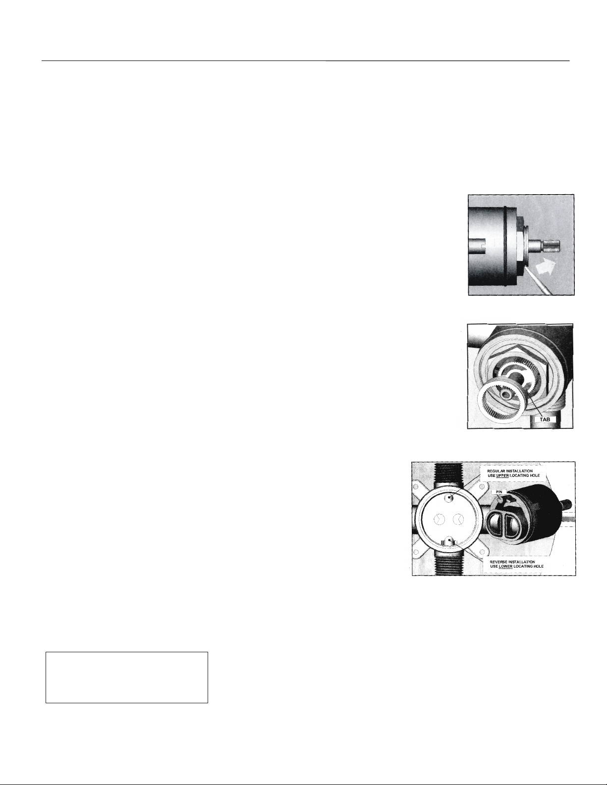
figure 4
figure 5
IMPORTANT!!!! SETTING HOT LIMIT STOP
The removal of the warning label barrier on the face of this mixing valve constitutes the transfer of liability from the manufacturer to
the installer under the laws of the United States. It is the installer's responsibility to set the maximum output temperature of the valve to
no more than 120°f, in accordance with ASSE/ANSI standard 1016 -1996 dealing with individual thermostatic, pressure balancing and
combination pressure balancing and thermostatic control valves for individual fixtures section 4.2,2., temperature limit setting.
TO PROPERLY SET THE LIMIT RING, YOU MUST USEA THERMOMETER OR CALIBRATED SENSING DEVICE TO ACCURATELY
MEASURE THE OUTLET WATER TEMPERATURE. THEADJUSTMENT RING IS POSITIONED AS FOLLOWS:
1. Expose the top of the cartridge by removing the trim sleeve from the valve body.
Do not remove the hex nut holding it in place. (See Figure 3)
2. Remove the grey adjustment ring by placing the blade of a knife into the
groove and prying it off (see figure 3).
3. Note the stop tab on the bottom of the ring (see figure 4). The further it is reoriented in a counter-
clockwise direction, the shorter the travel allowed (and thus, the lower the temperature output possible).
Important: before re-orienting the ring, be sure the stem is in the full off position.
REVERSING CARTRIDGE FOR BACK-TO-BACK INSTALLATIONS ONLY
When a valve is installed with reversed supply connections (typically in a back-to-back situation),
the cartridge can be reversed to allow normal operation (see figure 5).
1. Remove trim sleeve to expose top of valve.
2. Loosen and remove hex nut above cartridge.
3. Remove cartridge from valve cavity.. Look into cavity to see upper and lower locating
holes for cartridge pin.
4. Re-insert cartridge, aligning the pin with lower locating hole (partially cut away by
discharge opening). Press cartridge in firmly to assure that pin is properly inserted.
5. Secure cartridge by tightly reassembling The hex nut. Reassemble trim.
EPLACING CARTRIDGE
SAME BASIC PROCEDURE AS ABOVE (REVERSE IF NECESSARY).
Santec Inc.
3501 Challenger Street, Torrance, CA90503
Tel: (310) 542-0063 Fax (310) 542-5681
www.santecfaucet.com
PAGE 02


