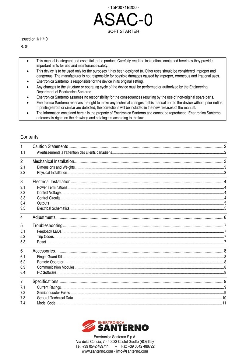
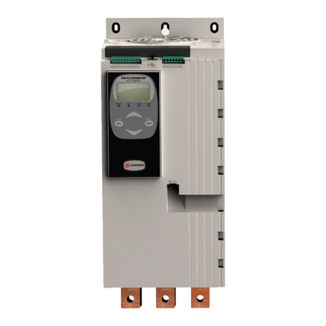
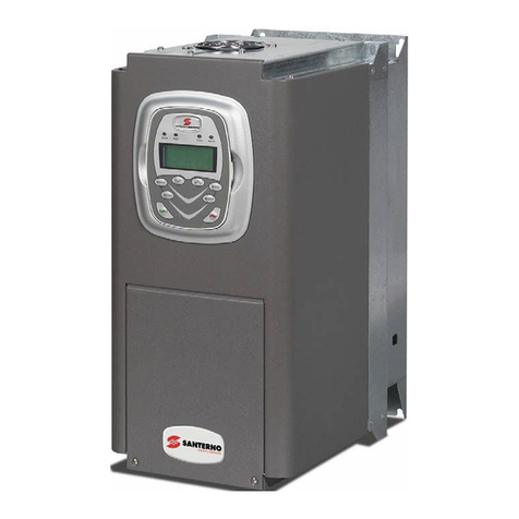
Santerno ASA 4.0 Advanced Specification sheet

Enertronica Santerno S.p.A.
Via della Concia, 7 - 40023 Castel Guelfo (BO) Italy
Tel. +39 0542 489711 –Fax +39 0542 489722
www.santerno.com - info@santerno.com
- 15V0093B100 -
ASA 4.0 Advanced
28BSOFT STARTER
QUICK SETUP
Issued on 01/08/18
R. 01
•This manualis integrant and essential to the product. Carefully read the instructions contained herein as
they provide important hints for use and maintenance safety.
•This device is to be used only for the purposes ithas been designed to. Other uses should be
considered improper and dangerous. The manufacturer is not responsible for possible damages caused
by improper, erroneous and irrational uses.
•Enertronica Santerno is responsible for the device in its original setting.
•Any changes to the structure or operating cycle of the device must be performed or authorized by the
Engineering Department of Enertronica Santerno.
•Enertronica Santerno assumes no responsibility for the consequences resulting by the use of
non-original spare parts.
•Enertronica Santerno reserves the right to make any technical changes to this manual and to the device
without prior notice. If printing errors or similar are detected, the corrections willbe included in the new
releases of the manual.
•The information contained herein is the property of Enertronica Santerno and cannot be reproduced.
Enertronica Santerno enforces its rights on the drawings and catalogues according to the law.

ASA 4.0 Advanced
1
Contents
1About This Manual.............................................................................................................................................2
1.1 Disclaimer ......................................................................................................................................................2
2Caution Statements...........................................................................................................................................3
2.1 Electrical shock risk.......................................................................................................................................3
2.2 Unexpected Operation..................................................................................................................................3
2.3 Avertissements à l'attention des clients canadiens.....................................................................................4
3SystemDesign...................................................................................................................................................6
3.1 Feature List....................................................................................................................................................6
3.2 ModelCode....................................................................................................................................................6
4Installation..........................................................................................................................................................7
4.1 Setup Procedure Overview...........................................................................................................................7
4.2 PhysicalInstallation.......................................................................................................................................8
4.3 ControlVoltage..............................................................................................................................................8
4.4 Power Terminations.......................................................................................................................................9
4.5 Typical Installation.......................................................................................................................................10
4.6 Quick Setup .................................................................................................................................................11
5Keypad and Feedback....................................................................................................................................12
5.1 The Keypad..................................................................................................................................................12
5.2 Starter status LEDs.....................................................................................................................................13
6Operation.........................................................................................................................................................13
6.1 Start, Stop and Reset Commands..............................................................................................................13
7Programmable Parameters.............................................................................................................................14
7.1 Parameter List..............................................................................................................................................14
8Specifications...................................................................................................................................................19
8.1 DisposalInstructions...................................................................................................................................20

2
ASA 4.0 Advanced
10BAbout This Manual
CAUTION
This manualprovides brief information to assist in installing and operating the ASA 4.0 Advanced in
simple applications. For comprehensive information on installing and operating the ASA 4.0
Advanced, refer to the ASA 4.0 Advanced User Manual (available from santerno.com).
WARNING
Indicates a hazard that may cause personal injury or death.
CAUTION
Indicates a hazard that may damage the equipment or installation.
NOTE
Provides helpful information.
1.1 8BDisclaimer
The examples and diagrams in this manual are included solely for illustrative purposes.
The information contained in this manual is subject to change at any time and without prior notice. In no event
will responsibility or liability be accepted for direct, indirect or consequential damages resulting from the use or
application of this equipment.

ASA 4.0 Advanced
3
21BCaution Statements
Caution Statements cannot cover every potential cause of equipmentdamage but can highlight common
causes of damage. It is the installer's responsibility to read and understand all instructions in this manual prior
to installing, operating or maintaining the equipment, to follow good electrical practice including applying
appropriate personalprotective equipment and to seek advice before operating this equipment in a manner
other than as described in this manual.
NOTE
The ASA 4.0 Advanced is notuser serviceable. The unit should only be serviced by authorised
service personnel. Unauthorised tampering with the unit will void the product warranty.
2.1 9BElectrical shock risk
WARNING – ELECTRICAL SHOCK RISK
The voltages present in the following locations can cause severe electric shock and may be lethal:
AC supply cables and connections
Outputcables and connections
Many internal parts of the starter
SHORT CIRCUIT
The ASA 4.0 Advanced is notshort circuitproof. After severe overload or short circuit, the operation of
the ASA4.0 Advanced should be fully tested by an authorised service agent.
GROUNDING AND BRANCH CIRCUIT PROTECTION
It is the responsibility of the user or person installing the ASA 4.0 Advanced to provide proper
grounding and branch circuitprotection according to local electricalsafety codes.
FOR YOUR SAFETY
The STOP function of the soft starter does not isolate dangerous voltages from the output of the
starter. The soft starter must be disconnected by an approved electricalisolation device before
accessing electricalconnections.
Softstarter protection features apply to motor protection only. It is the user’s responsibility to
ensure safety of personnel operating machinery.
The softstarter is a component designed for integration within an electricalsystem; it is therefore
the responsibility of the system designer/user to ensure the systemis safe and designed to
comply with relevant local safety standards.
2.2 10BUnexpected Operation
WARNING – ACCIDENTAL STARTS
In some installations,accidental starts may pose an increased risk to safety of personnel or damage to
the machines being driven. In such cases, it is recommended that the power supply to the soft starter
is fitted with an isolating switch and a circuit-breaking device (eg power contactor) controllable through
an external safety system (eg emergency stop, fault detector).
WARNING – STARTER MAY START OR STOP UNEXPECTEDLY
The ASA 4.0 Advanced will respond to control commands from various sources, and could start or
stop unexpectedly. Always disconnectthe soft starter from mains voltage before accessing the starter
or load.
WARNING – DISCONNECT MAINS BEFORE ACCESSING STARTER OR LOAD
The softstarter has built-in protections which can trip the starter in the event of faults and thus stop the
motor. Voltage fluctuations, power cuts and motor jams may also cause the motor to trip.
The motor could restart after the causes of shutdown are rectified, which may be dangerous for
personnel. Always disconnect the soft starter from mains voltage before accessing the starter or load.

4
ASA 4.0 Advanced
CAUTION – MECHANICAL DAMAGE FROM UNEXPECTED RESTART
The motor could restart after the causes of shutdown are rectified, which may be dangerous for certain
machines or installations. In such cases, it is essential that appropriate arrangements are made
against restarting after unscheduled stops of the motor.
2.3 11BAvertissements à l'attention des clients canadiens
AVERTISSEMENT
L'icône AVERTISSEMENT ci-contre signale les informations concernantdes risques pouvant
entraîner des blessures graves,voire mortelles. Pour votre sécurité, veuillez consulter les
avertissements sur cette page ou demander une copie du présent manuelen français auprès de votre
distributeur local.
AVERTISSEMENT – RISQUE DE CHOC ÉLECTRIQUE
Les zones suivantes sontsoumises à des tensions pouvantprovoquer des risques de chocs
électriques graves,voire mortels :
Raccordement etcâbles d'alimentation AC
Câbles etraccordements de sortie
De nombreuses pièces internes du démarreur
PAR SÉCURITÉ
La fonction STOP du démarreur progressif n'isole pas des tensions dangereuses de la sortie du
démarreur. Le démarreur progressif doit être déconnecté par un dispositif d'isolement électrique
approprié avant d'accéder aux connexions électriques.
Les fonctions de protection du démarreur progressif ne concernent que la protection du moteur. Il
relève de la responsabilité de l'utilisateur d'assurer la sécurité des personnes travaillant sur les
machines.
Le démarreur progressifestun appareil conçu pour s'intégrer dans un système électrique ; il
relève donc de la responsabilité du concepteur ou de l'utilisateur de veiller à ce que ce système
soit sûr etconçu selon les normes de sécurité locales en vigueur.
AVERTISSEMENT – DÉMARRAGES ACCIDENTELS
Dans certaines installations, des démarrages accidentels peuventprovoquer un risque
supplémentaire pour la sécurité des personnes ou endommager les machines contrôlées. Dans de
tels cas, il est recommandé de doter l'alimentation du démarreur progressif d'un interrupteur
d'isolementetd'un coupe-circuit (par exemple, un disjoncteur) contrôlable à partir d'un système de
sécurité externe (par exemple,un arrêt d'urgence, un détecteur de défaut).
AVERTISSEMENT – LE DÉMARREUR PEUT DÉMARRER OU S'ARRÊTER À TOUT MOMENT
L’ASA4.0 Advanced répond aux commandes de contrôle de différentes origines et peut par
conséquent démarrer ou s'arrêter à tout moment. Toujours déconnecter le démarreur de la tension
secteur avantd'accéder au démarreur ouà la charge.
AVERTISSEMENT – DÉCONNECTER L'ALIMENTATION PRINCIPALE AVANT D'ACCÉDER AU
DÉMARREUR OU À LA CHARGE
Le démarreur progressif comportedes protections intégrées qui peuvent déclencher des mises en
sécurité dans l'éventualité de défauts et ainsi arrêter le moteur. Des fluctuations de tension, des
coupures d'alimentation et des blocages du moteur peuvent produire des mises en sécurité de
celui-ci.
Le moteur pourraitredémarrer une fois que les causes de l'arrêt ont été résolues,ce qui pourrait
mettre en danger le personnel. Toujours déconnecter le démarreur de la tension secteur avant
d'accéder au démarreur ou à la charge.
AVERTISSEMENT
Ne pas appliquer la tension du secteur au démarreur tant que tout le câblage n'est pas terminé.
ASA 4.0 Advanced
5
AVERTISSEMENT
Toujours appliquer la tension de commande avant (ou en même temps que) la tension secteur.
AVERTISSEMENT
Lors du raccordement de l’ASA 4.0 Advanced en connexion 6 fils, toujours installer un contacteur
principal ou un disjoncteur magnéto-thermique à bobine de déclenchement.
AVERTISSEMENT
Si l'entrée de démarrage est fermée lorsque la tension de commande estappliquée, le démarreur
tentera d'effectuer un démarrage.
Vérifier que l'entrée de démarrage/arrêt est ouverte avant d'appliquer la tension de commande.

6
ASA 4.0 Advanced
32BSystem Design
3.1 12BFeature List
Streamlined setup process
•Configuration profiles for common applications
•Built-in metering and inputs/outputs
Easy to understand interface
•Multi-language menus and displays
•Descriptive option names and feedback messages
•Real-time performance graphs
Supports energy efficiency
•IE3 compatible
•99% energy efficientwhen running
•Internal bypass
•Softstart technology avoids harmonic distortion
Extensive range of models
•24 A~580 A (nominal)
•200~525 VAC
•380~690 VAC
•Inside delta installation
Extensive input and output options
•Remote control inputs
(2 x fixed,2 x programmable)
•Relay outputs
(1 x fixed,2 x programmable)
•Analog output
Versatile starting and stopping options
•Scheduled start/stop
•Adaptive Control
•ConstantCurrent
•Current Ramp
•Pump Clean
•Timed voltage ramp soft stop
•Coast To Stop
•DC Brake
•Soft Brake
•Reverse Direction
Customisable protection
•Motor overload
•Excess Start Time
•Undercurrent/Overcurrent
•Underpower/Overpower
•Undervoltage/Overvoltage
•Current imbalance
•InputTrip
•Motor thermistor
Optional features for advanced applications
•Smartcards
•Communication options: DeviceNet,
Ethernet/IP, Modbus RTU, Modbus TCP,
Profibus,Profinet
3.2 13BModel Code
ASA4.0-A
–
/
/
Controlvoltage
12 = 110~120 VAC or 220~240 VAC
14 = 24 VAC/VDC
Mains voltage
5 = 200~525 VAC
7 = 380~690 VAC
Bypass
B = internally bypassed
Nominalcurrent rating

ASA 4.0 Advanced
7
43BInstallation
WARNING
Do not apply mains voltage to the starter until all wiring is complete.
WARNING
Always apply control voltage before (or with) mains voltage.
4.1 14BSetup Procedure Overview
1. Mountthe soft starter (refer toPhysical Installation on page 8 for details).
2. Connect control wiring (refer to Control Inputs for details).
3. Applycontrol voltage to the starter.
4. Configure your application:
1. Press MENU to open the Menu.
2. Press to open the Quick Setup menu.
3. Scroll through the list to find your application, then press to begin the configuration process (refer to
Quick Setup on page 11 for details).
5. Ifyour application is not listed in Quick Setup:
1. Press to return to the Menu.
2. Use to scrollto Main Menu and press .
3. Scroll to Motor Details and press , then press again to edit parameter 1B Motor Full Load
Current.
4. Setparameter 1Bto match the motor's full load current (FLC).
5. Press to save the setting.
6. Close the Menu by pressing repeatedly.
7. (Optional) Use the built-in simulation tools to check that the control wiring is connected correctly (refer to
Run Simulation).
8. Power off the soft starter.
9. Connectthe motor cablesto starter output terminals 2/T1,4/T2, 6/T3.
10. Connect mains supply cables to starter input terminals 1/L1, 3/L2, 5/L3 (refer to Power Terminations on
page 9).
The softstarter is now ready to control the motor.

8
ASA 4.0 Advanced
4.2 15BPhysical Installation
DD
18542.A
C
C
B
A
2/T1 4/ T2 6/T3
33 34 41 42 44 53 54
2/T1 4/ T2 6/T3
B4 B5 1011 12 13 14 15 21 22
A3 A1 A2
33 34 41 42 44 53 54
2/T1 4/ T2 6/T3
B4 B5 1011 12 13 14 15 21 22
A3 A1 A2
33 34 41 42 44 53 54
2/T1 4/ T2 6/T 3
B4 B5 1011 12 13 14 15 21 22
A3 A1A2
33 34 41 42 44 53 54
2/T1 4/ T2 6/T 3
B4 B5 1011 12 13 14 15 21 22
A3 A1A2
33 34 41 42 44 53 54
2/T1 4/ T2 6/T 3
B4 B5 1011 12 13 14 15 21 22
A3 A1A2
Between starters
Solid surfaces
A
B
C
D
> 100 mm (3.9 inch)
> 10 mm (0.4 inch)
> 100 mm (3.9 inch)
> 10 mm (0.4 inch)
4.3 16BControl Voltage
4.3.1 25BControl Voltage Terminals
A3 A1 A2
2/T1 4/T2 6/T3
1/L1 3/L2 5/L3
B4 B5 10 11 12 13 14 15 21 22 33 34 41 42 44 53 54
A3 A1 A2
Connect the control supply according to the supply voltage being used.
•ASA4.0-AxxxxB/x/12 (110~120 VAC): A1, A2
•ASA4.0-A xxxxB/x/12 (220~240 VAC): A2, A3
•ASA4.0-AxxxxB/x/14 (24 VAC/VDC): A1, A2
4.3.2 26BUL Compliant Installation
For models ASA4.0-A 0184B to ASA4.0-A 0580B to be UL compliant, supplementary or branch overcurrent
protection must be used on the control circuit supply (A1, A2, A3), in accordance with the electrical code
applicable atthe installation location.

ASA 4.0 Advanced
9
4.4 17BPower Terminations
The power input and output terminals for ASA 4.0 Advanced are at the bottom of the unit.
•Models ASA4.0-A 0024B~ASA4.0-A 0135B use cage clamps. Use only copper stranded or solid
conductors, rated for 75 ºC or higher.
•Models ASA4.0-A 0184B~ASA4.0-A 0580B use busbars. Use copper or aluminiumconductors,
stranded or solid, rated for 60 ºC/75 ºC.
NOTE
Some units use aluminium busbars. When connecting power terminations, we recommend cleaning
the surface contact area thoroughly (using an emery or stainless steel brush) and using an appropriate
jointing compound to prevent corrosion.
ASA4.0-A 0024B~ASA4.0-A 0135B
05966.E
Cable size:
6-70 mm2(AWG 10-2/0)
Torque: 4 Nm (2.9 ft-lb)
Torx T20 x 150
Flat7 mm x 150
11290.A
14 mm (0.55 inch)
ASA4.0-A 0184B~ASA4.0-A 0250B
ASA4.0-A 0352B~ASA4.0-A 0580B
19 Nm(14.0 ft-lb)
66 Nm(49.0 ft-lb)
6 mm
20 mm
9 mm
(M8)
17045.A
6 mm
34 mm
13 mm
(M12)
17047.A
NOTE
If the installation requires large diameter cables, it is possible to complete each termination with two
smaller cables, one on each side of the busbar.
4.4.1 27BUL Compliant Installation
For models ASA4.0-A 0184B to ASA4.0-A 0580B to be UL compliant, you must use the recommended pressure
terminal/connector.
Model
Recommended lugs part No.
ASA4.0-A 0184B
OPHD 185-10
ASA4.0-A 0200B
ASA4.0-A 0229B
ASA4.0-A 0250B
ASA4.0-A 0352B
ASA4.0-A 0397B
OPHD 150-12
ASA4.0-A 0410B
ASA4.0-A 0550B
OPHD 240-12
ASA4.0-A 0580B

10
ASA 4.0 Advanced
4.5 18BTypical Installation
The ASA 4.0 Advanced is installed with a main contactor (AC3 rated). Control voltage must be supplied from
the input side of the contactor.
The main contactor is controlled by the main contactor output (33, 34).
A+
M
42
41
6/T3
2/T1
33
34
4/T2
54
53
44
21
22
B5
B4
12
13
14
15
11
A2
A1
A3
5/L3
3/L2
10
1/L1
F1
S1
S2 K1
K1
7
6
5
3
2
1
10
4
9
8
17674.B
(L/+)
1
Three-phase supply
K1
Main contactor
2
Motor
F1
Semiconductor fuses (optional)
3
Control voltage (soft starter)
10, 11 (S1)
Reset
4
Digital inputs
11, 12 (S2)
Start/Stop
5
Motor thermistor input
13,14
Programmable input A
(default= InputTrip (N/O))
6
Relay outputs
13,15
Programmable input B
(default= InputTrip (N/O))
7
Analog output
B4, B5
Motor thermistor input
8
Control voltage (external equipment)
33,34
Main contactor output
9
Pilot lamps
41,42, 44
Relay output A (default = Run)
10
Communications / Smart card
expansion port
53,54
Relay output B (default = Run)
21,22
Analog output

ASA 4.0 Advanced
11
4.6 19BQuick Setup
The Quick Setup Menu makes it easy to configure the ASA 4.0 Advanced for common applications. The ASA
4.0 Advanced guides you through the most common installation parameters, and suggests a typical setting for
the application. You can adjusteach parameter to suit your exact requirements.
All other parameters remain atdefault values. To change other parameter values or review the default settings,
use the menu (refer to Parameter List for details).
Always set parameter 1B Motor Full Load Currentto match the motor's nameplate full load current.
Application
Start Mode
Start Ramp Time
(seconds)
Initial Current
(%)
Current Limit
(%)
Adaptive Start
Profile
Stop Mode
Stop Time
(seconds)
Adaptive Stop
Profile
Pump Centrifugal
Adaptive
Control
10
200
500
Early accel.
Adaptive
Control
15
Late decel.
Pump bore
Adaptive
Control
3
200
500
Early accel.
Adaptive
Control
3
Late decel.
Pump Hydraulic
Constant
Current
2
200
350
n/a
Coast To Stop
n/a
n/a
Fan Damped
Constant
Current
2
200
350
n/a
Coast To Stop
n/a
n/a
Fan Undamped
Constant
Current
2
200
450
n/a
Coast To Stop
n/a
n/a
Compressor Screw
Constant
Current
2
200
400
n/a
Coast To Stop
n/a
n/a
Compressor Recip
Constant
Current
2
200
450
n/a
Coast To Stop
n/a
n/a
Conveyor
Constant
Current
5
200
450
n/a
Coast To Stop
n/a
n/a
Bowthruster
Constant
Current
5
100
400
n/a
Coast To Stop
n/a
n/a
Bandsaw
Constant
Current
2
200
450
n/a
Coast To Stop
n/a
n/a
NOTE
The Adaptive Start and Stop Profile settings only apply when using Adaptive Control.The settings are
ignored for allother start and stop modes.

12
ASA 4.0 Advanced
54BKeypad and Feedback
5.1 20BThe Keypad
Local keypad
Remote keypad (if installed)
LocalReady Run Trip
Exit Enter
MenuReset
1
2
3
1
2
3
4
5
6
1
Four-line display for status and programming details.
2
Status LEDs
3
Menu navigation buttons:
: Exit the menu or parameter, or cancela parameter change. On the local keypad, this button also
resets a trip.
: Enter a menu or parameter, or save aparameter change.
:Scrollto the next or previous menu or parameter, change the setting of the current parameter or
scroll through the status screens.
4
Shortcut to the command source menu in Setup Tools.
5
Softstarter local control buttons
6
Shortcutbuttons for quick access to common tasks.
LOGS: Open the Logs Menu.
GRAPHS: Select which graph to view, or pause/restart the graph (hold longer than 0.5 seconds)
TOOLS: Open the Setup Tools.

ASA 4.0 Advanced
13
5.2 21BStarter status LEDs
Ready Run Trip Local
17694.A
LED name
On
Flashing
Ready
The motor is stopped and the starter is ready
to start.
The motor is stopped and the starter is not
ready to start:
•waiting for the RestartDelay (parameter
5P)
•the thermal models indicate the starter
and/or motor are too hot to startsafely
•
the reset input (10,11) is open
Run
The motor is in run state (receiving full
voltage).
The motor is starting or stopping.
Trip
The starter has tripped.
The starter is in warning state.
Local
The starter is being controlled via a remote
keypad.
–
IfallLEDs are off, the starter is not receiving control voltage.
65BOperation
6.1 22BStart, Stop and Reset Commands
The ASA 4.0 Advanced can be started and stopped via the digital inputs, remote keypad, communication
network, smart card or scheduled auto-start/stop.The command source can be set via the Setup Tools, or
using parameter 1A Command Source.
•The ASA 4.0 Advanced will only accept Start and Reset commands from the designated command
source.
•The ASA 4.0 Advanced will accept Stop commands from the designated command source, but can be
forced to stop by opening the reset input, or by opening the start/stop input during an auto-start/stop
cycle.
•The programmable input can be used to override the selected command source (refer to parameter 7A
InputA Function).

14
ASA 4.0 Advanced
76BProgrammable Parameters
7.1 23BParameter List
Parameter Group
Default Setting
1
Motor Details
1A
Command Source
Digital Input
1B
Motor Full Load Current
Model dependent
1C
Motor kW
0 kW
1D
Locked Rotor Time
00:10 (mm:ss)
1E
Locked Rotor Current
600%
1F
Motor Service Factor
105%
1G
Reserved
2
Motor Start/Stop
2A
StartMode
ConstantCurrent
2B
Start Ramp Time
00:10 (mm:ss)
2C
Initial Current
200%
2D
Current Limit
350%
2E
Adaptive Start Profile
ConstantAcceleration
2F
KickstartTime
000 ms
2G
KickstartLevel
500%
2H
Jog Torque
50%
2I
Stop Mode
TVR Soft Stop
2J
Stop Time
00:00 (mm:ss)
2K
Adaptive Stop Profile
ConstantDeceleration
2L
Adaptive Control Gain
75%
2M
Multi Pump
Single Pump
2N
StartDelay
00:00 (mm:ss)
2O
DC Brake Torque
20%
2P
DC Brake Time
00:01 (mm:ss)
2Q
Brake Current Limit
250%
2R
SoftBrake Delay
400 ms
3
Motor Start/Stop 2
3A
Motor Full Load Current-2
Model dependent
3B
Motor kW-2
0 kW
3C
StartMode-2
ConstantCurrent
3D
Start Ramp Time-2
00:10 (mm:ss)
3E
Initial Current-2
200%
3F
Current Limit-2
350%
3G
Adaptive Start Profile-2
ConstantAcceleration
3H
KickstartTime-2
000 ms
3I
KickstartLevel-2
500%
3J
Jog Torque-2
50%
3K
Stop Mode-2
TVR Soft Stop
3L
Stop Time-2
00:00 (mm:ss)
3M
Adaptive Stop Profile-2
ConstantDeceleration
3N
Adaptive Control Gain-2
75%
3O
Multi Pump-2
Single Pump
3P
StartDelay-2
00:00 (mm:ss)
3Q
DC Brake Torque-2
20%
3R
DC Brake Time-2
00:01 (mm:ss)
3S
Brake Current Limit-2
250%
3T
SoftBrake Delay-2
400 ms

ASA 4.0 Advanced
15
Parameter Group
Default Setting
4
Auto-Start/Stop
4A
Auto-Start/Stop Mode
Disable
4B
Run Time
00:00 (hh:mm)
4C
Stopped Time
00:00 (hh:mm)
4D
Sunday Mode
Start/Stop Disable
4E
Sunday Start Time
00:00 (hh:mm)
4F
Sunday Stop Time
00:00 (hh:mm)
4G
Monday Mode
Start/Stop Disable
4H
Monday Start Time
00:00 (hh:mm)
4I
Monday Stop Time
00:00 (hh:mm)
4J
Tuesday Mode
Start/Stop Disable
4K
Tuesday StartTime
00:00 (hh:mm)
4L
Tuesday Stop Time
00:00 (hh:mm)
4M
Wednesday Mode
Start/Stop Disable
4N
Wednesday Start Time
00:00 (hh:mm)
4O
Wednesday Stop Time
00:00 (hh:mm)
4P
Thursday Mode
Start/Stop Disable
4Q
Thursday Start Time
00:00 (hh:mm)
4R
Thursday Stop Time
00:00 (hh:mm)
4S
Friday Mode
Start/Stop Disable
4T
Friday StartTime
00:00 (hh:mm)
4U
Friday Stop Time
00:00 (hh:mm)
4V
Saturday Mode
Start/Stop Disable
4W
Saturday Start Time
00:00 (hh:mm)
4X
Saturday Stop Time
00:00 (hh:mm)
5
Protection Levels
5A
Current Imbalance
30%
5B
Current Imbalance Delay
00:03 (mm:ss)
5C
Undercurrent
20%
5D
UndercurrentDelay
00:05 (mm:ss)
5E
Overcurrent
400%
5F
OvercurrentDelay
00:00 (mm:ss)
5G
Undervoltage
350 V
5H
Undervoltage Delay
00:01 (mm:ss)
5I
Overvoltage
500 V
5J
Overvoltage Delay
00:01 (mm:ss)
5K
Underpower
10%
5L
Underpower Delay
00:01 (mm:ss)
5M
Overpower
150%
5N
Overpower Delay
00:01 (mm:ss)
5O
Excess Start Time
00:20 (mm:ss)
5P
RestartDelay
00:10 (mm:ss)
5Q
Starts per Hour
0
5R
Phase Sequence
Any Sequence
6
Protection Actions
6A
Auto-ResetCount
0
6B
Auto-ResetDelay
00:05 (mm:ss)
6C
Current Imbalance
SoftTrip and Log
6D
Undercurrent
SoftTrip and Log
6E
Overcurrent
SoftTrip and Log
6F
Undervoltage
SoftTrip and Log
6G
Overvoltage
SoftTrip and Log

16
ASA 4.0 Advanced
Parameter Group
Default Setting
6H
Underpower
Log Only
6I
Overpower
Log Only
6J
Excess Start Time
SoftTrip and Log
6K
InputA Trip
SoftTrip and Log
6L
InputB Trip
SoftTrip and Log
6M
Network Communications
SoftTrip and Log
6N
Remote Keypad Fault
SoftTrip and Log
6O
Frequency
SoftTrip and Log
6P
Phase Sequence
SoftTrip and Log
6Q
Motor Overtemperature
SoftTrip and Log
6R
Motor Thermistor Circuit
SoftTrip and Log
6S
Shorted SCRAction
3-Phase Control Only
6T
Battery/Clock
SoftTrip and Log
7
Inputs
7A
InputA Function
InputTrip (N/O)
7B
InputA Trip
Operating Only
7C
InputA Trip Delay
00:00 (mm:ss)
7D
InputA Initial Delay
00:00 (mm:ss)
7E
InputB Function
InputTrip (N/O)
7F
InputB Trip
Operating Only
7G
InputB Trip Delay
00:00 (mm:ss)
7H
InputB Initial Delay
00:00 (mm:ss)
7I
Reset/Enable Logic
Normally Closed (N/C)
7J
InputA Name
InputA Trip
7K
InputB Name
InputB Trip
8
Relay Outputs
8A
Relay A Function
Run
8B
Relay A On Delay
00:00 (mm:ss)
8C
Relay A Off Delay
00:00 (mm:ss)
8D
Relay B Function
Run
8E
Relay B On Delay
00:00 (mm:ss)
8F
Relay B Off Delay
00:00 (mm:ss)
8G
Low Current Flag
50%
8H
High Current Flag
100%
8I
Motor Temperature Flag
80%
8J
Main Contactor Time
400 ms
9
Analog Output
9A
Analog Output A
Current (% FLC)
9B
Analog A Scale
4-20 mA
9C
Analog A MaximumAdjustment
100%
9D
Analog A Minimum Adjustment
000%
10
Display
10A
Language
English
10B
Temperature Scale
Celsius
10C
Graph Timebase
30 seconds
10D
Graph Maximum Adjustment
400%
10E
Graph Minimum Adjustment
0%
10F
Current Calibration
100%
10G
AdjustmentLock
Read & Write
10H
User Parameter 1
Current
10I
User Parameter 2
Motor Voltage

ASA 4.0 Advanced
17
Parameter Group
Default Setting
10J
User Parameter 3
Mains Frequency
10K
User Parameter 4
Motor pf
10L
User Parameter 5
Motor Power
10M
User Parameter 6
Motor Temperature (%)
11
Pump Clean
11A
Reverse Torque
20%
11B
Reverse Time
00:10 (mm:ss)
11C
Forward Current Limit
100%
11D
Forward Time
00:10 (mm:ss)
11E
Pump Stop Mode
Coast To Stop
11F
Pump Stop Time
00:10 (mm:ss)
11G
Pump Clean Cycles
1
12
Communications Card
12A
Modbus Address
1
12B
Modbus Baud Rate
9600
12C
Modbus Parity
None
12D
Modbus Timeout
Off
12E
DevicenetAddress
0
12F
DevicenetBaud Rate
125kB
12G
Profibus Address
1
12H
Gateway Address
192
12I
Gateway Address 2
168
12J
Gateway Address 3
0
12K
Gateway Address 4
100
12L
IP Address
192
12M
IP Address 2
168
12N
IP Address 3
0
12O
IP Address 4
2
12P
SubnetMask
255
12Q
Subnet Mask 2
255
12R
Subnet Mask 3
255
12S
Subnet Mask 4
0
12T
DHCP
Disable
12U
Location ID
0
20
Advanced
20A
Tracking Gain
50%
20B
PedestalDetect
80%
20C
Bypass Contactor Delay
150 ms
20D
ModelRating
Model dependent
20E
Screen Timeout
1 minute
20F
Motor Connection
Auto-detect
30
Pump Input Configuration
30A
Pressure Sensor Type
None
30B
Pressure Units
kPa
30C
Pressure at 4 mA
0
30D
Pressure at 20 mA
0
30E
FlowSensor Type
None
30F
Flow Units
litres/second
30G
Flow at 4 mA
0
30H
Flow at 20 mA
0
30I
Units per Minute at Max Flow
0
30J
Pulses per Minute at Max Flow
0

18
ASA 4.0 Advanced
Parameter Group
Default Setting
30K
Units per Pulse
0
30L
Depth Sensor Type
None
30M
Depth Units
metres
30N
Depth at 4 mA
0
30O
Depth at 20 mA
0
31
Flow Protection
31A
High Flow Trip Level
10
31B
Low FlowTrip Level
5
31C
FlowStart Delay
00:00:50 (mm:ss:ms)
31D
Flow Response Delay
00:00:50 (mm:ss:ms)
32
Pressure Protection
32A
High Pressure Trip Level
10
32B
High Pressure Start Delay
00:00:50 (mm:ss:ms)
32C
High Pressure Response Delay
00:00:50 (mm:ss:ms)
32D
Low Pressure Trip Level
5
32E
Low Pressure Start Delay
00:00:50 (mm:ss:ms)
32F
Low Pressure Response Delay
00:00:50 (mm:ss:ms)
33
Pressure Control
33A
Pressure Control Mode
Off
33B
Start Pressure Level
5
33C
Start Response Delay
00:00:50 (mm:ss:ms)
33D
Stop Pressure Level
10
33E
Stop Response Delay
00:00:50 (mm:ss:ms)
34
Depth Protection
34A
Depth Trip Level
5
34B
Depth Reset Level
10
34C
Depth Start Delay
00:00:50 (mm:ss:ms)
34D
Depth Response Delay
00:00:50 (mm:ss:ms)
35
Thermal Protection
35A
Temperature Sensor Type
None
35B
Temperature Trip Level
40
36
Pump Trip Action
36A
Pressure Sensor
SoftTrip and Log
36B
FlowSensor
SoftTrip and Log
36C
Depth Sensor
SoftTrip and Log
36D
High Pressure
SoftTrip and Log
36E
LowPressure
SoftTrip and Log
36F
High Flow
SoftTrip and Log
36G
LowFlow
SoftTrip and Log
36H
Flow Switch
SoftTrip and Log
36I
WellDepth
Soft Trip and Log
36J
RTD/PT100 B
SoftTrip and Log

ASA 4.0 Advanced
19
87BSpecifications
29BSupply
Mains voltage (L1, L2, L3)
ASA4.0-AxxxxB/5/xx .................................................................................................. 200~525 VAC (± 10%)
ASA4.0-AxxxxB/7/xx .................................................................................................. 380~690 VAC (± 10%)
Control voltage (A1, A2, A3)
ASA4.0-A xxxxB/x/12 (A1,A2) ........................................................... 110~120 VAC (+10%/-15%), 600 mA
ASA4.0-A xxxxB/x/12 (A2,A3) ........................................................... 220~240 VAC (+10%/-15%), 600 mA
ASA4.0-A xxxxB/x/14 (A1,A2) ......................................................................... 24 VAC/VDC (± 20%), 2.8 A
Mains frequency ................................................................................................................... 50 Hz~60 Hz (±5 Hz)
Rated insulation voltage to earth .............................................................................................................. 600 VAC
Rated impulse withstand voltage ..................................................................................................................... 6 kV
Form designation ................................................. Bypassed or continuous, semiconductor motor starter form 1
30BShort circuit capability
Coordination with semiconductor fuses ...................................................................................................... Type 2
Coordination with HRC fuses ...................................................................................................................... Type 1
31BElectromagnetic capability (compliant with EU Directive 2014/35/EU)
EMC Immunity ................................................................................................................................. IEC60947-4-2
EMCEmissions ................................................................................................................. IEC60947-4-2 Class B
32BInputs
Inputrating ................................................................................................................ Active 24 VDC, 8 mA approx
Motor thermistor (B4, B5) ......................................................................................... Trip >3.6 kΩ, reset<1.6 kΩ
33BOutputs
Relay outputs ................................................................ 10 A @ 250 VAC resistive, 5A @ 250 VAC AC15 pf0.3
Main contactor (33, 34) ............................................................................................................ Normally Open
Relay output A (41, 42, 44) ......................................................................................................... Changeover
Relay output B (53, 54) ............................................................................................................ Normally Open
Analog output (21, 22)
Maximum load ...................................................................................................... 600 Ω(12 VDC @ 20 mA)
Accuracy ................................................................................................................................................... ± 5%
34BEnvironmental
Operating temperature .......................................................................... -10 ˚C~60 ˚C, above 40 ˚C with derating
Storage temperature ..................................................................................................................... -25 °C~+ 60 °C
Operating Altitude .................................................................................... 0~1000 m, above 1000 m with derating
Humidity ...................................................................................................................... 5%~95% Relative Humidity
Pollution degree ........................................................................................................................ Pollution Degree 3
Vibration ........................................................................................................................................... IEC60068-2-6
Protection
ASA4.0-A 0024B~ASA4.0-A 0135B ........................................................................................................ IP20
ASA4.0-A 0184B~ASA4.0-A 0580B ........................................................................................................ IP00
35BHeat dissipation
During Start ........................................................................................................................... 4.5 watts per ampere
During Run
ASA4.0-A 0024B~ASA4.0-A 0052B .................................................................................. ≤ 35 watts approx
ASA4.0-A 0064B~ASA4.0-A 0135B .................................................................................. ≤ 50 watts approx
ASA4.0-A 0184B~ASA4.0-A 0250B ............................................................................... ≤ 120 watts approx
ASA4.0-A 0352B~ASA4.0-A 0580B ............................................................................... ≤ 140 watts approx
36BMotor Overload Protection
Default: The default settings of parameters 1D, 1E and 1F provide Motor Overload Protection: Class 10, Trip
Current 105% ofFLA (full load amperage) or equivalent.
Other manuals for ASA 4.0 Advanced
1
Table of contents
Other Santerno Controllers manuals

Santerno
Santerno ASAC-0 User manual

Santerno
Santerno ASA 4.0 Advanced User manual

Santerno
Santerno Sinus Penta User manual

Santerno
Santerno ASAB Technical specifications

Santerno
Santerno ASAC-0 User manual

Santerno
Santerno Sinus M User manual

Santerno
Santerno SINUS PENTA Series User manual

Santerno
Santerno Sinus Penta Quick manual