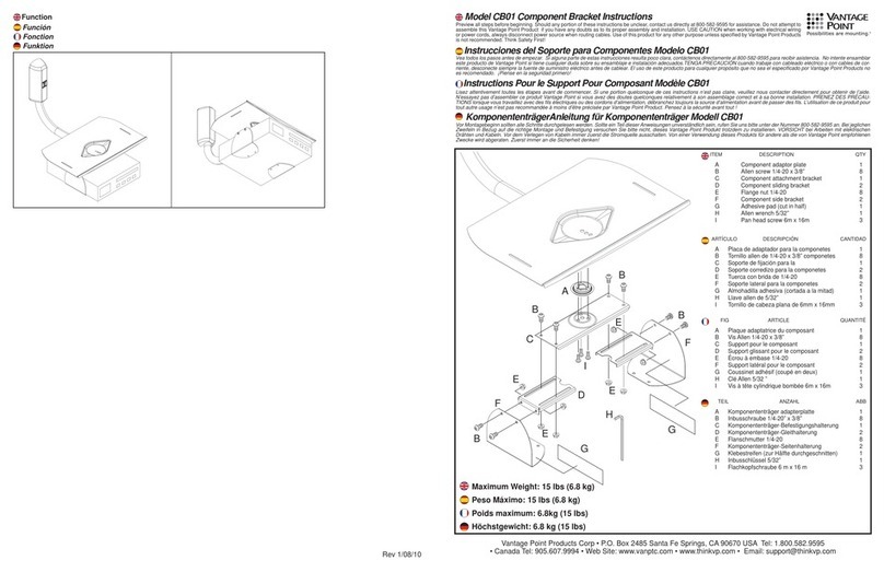
M4 x 12mm
M8 x 16mm
M8 x 20mm
M4 x 35mm
M8 x 35mm
M6 x 12mm
M6 x 35mm
M6 x 20mm
M6/M8
M4/M5
M5 x 12mm
M5 x 35mm
#10 x 2 1/2 in.
09
M4
M6
M8
M5
1
2
12 3 4
3
12 3
01
14
15
15
15
A
02 03
04 05 06 07 08 09
B
14 02 03
10 11 12 13
01
C1
x2
18
18
16
16
C1*
*
17
17
12
15
Min. 16 in.
(406 mm)
Min. 16 in.
(406 mm)
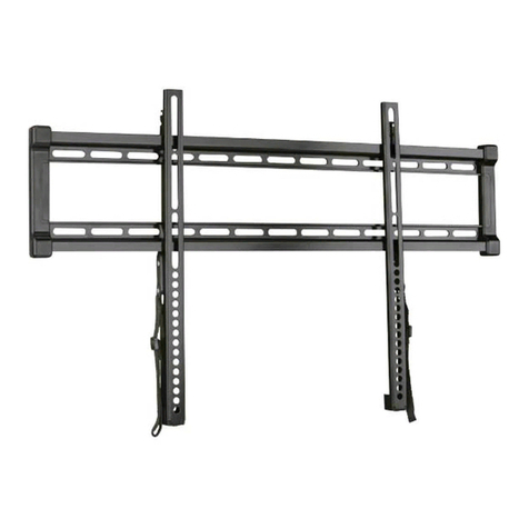
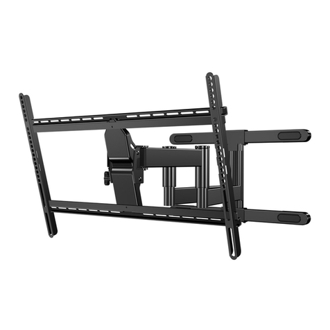
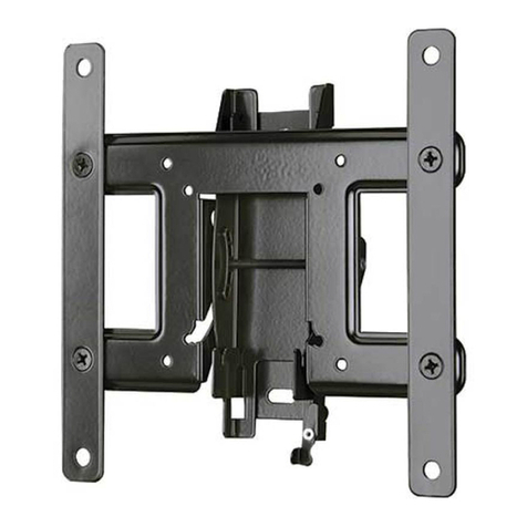
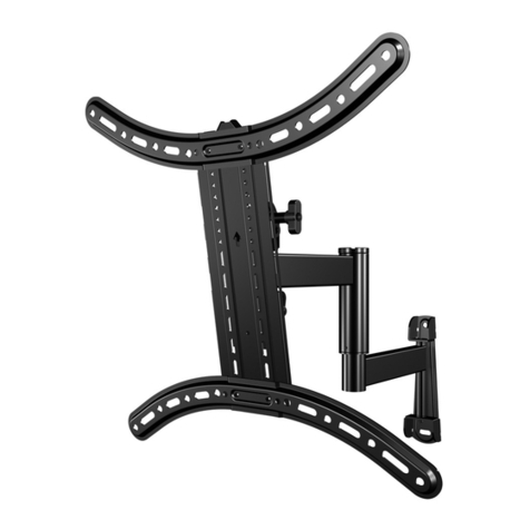
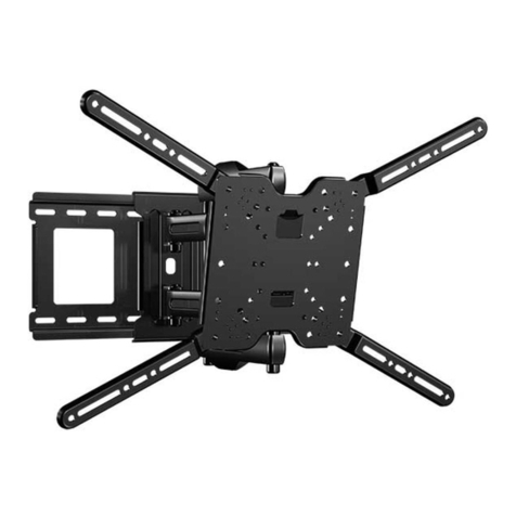
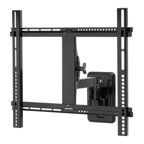
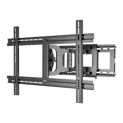
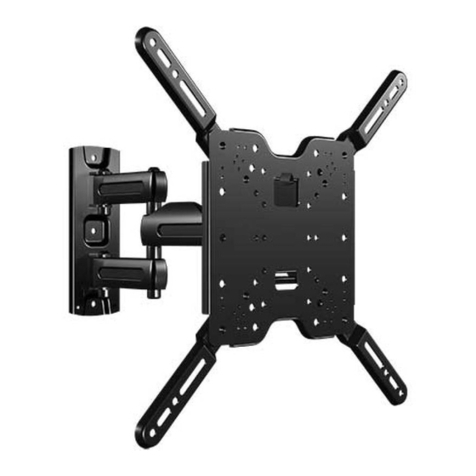
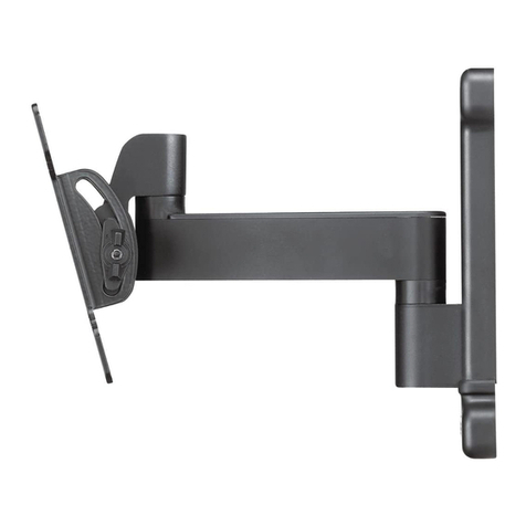
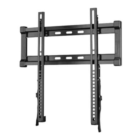
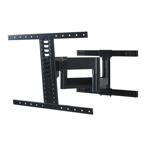
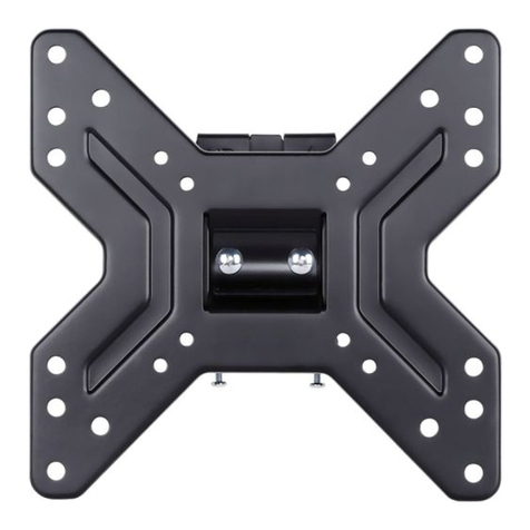
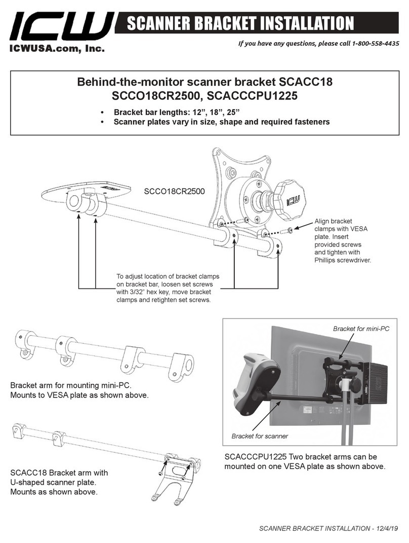
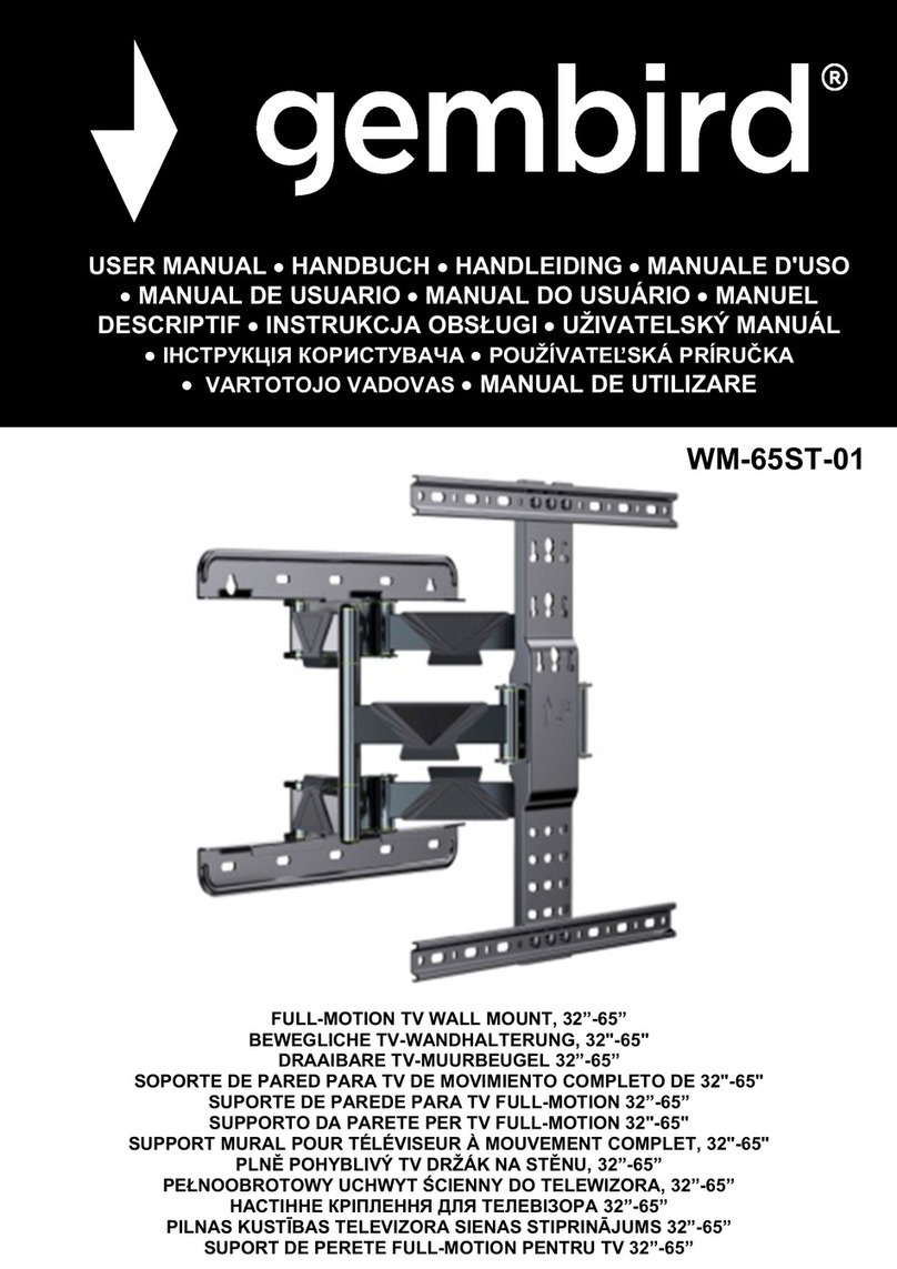
TV Bracket
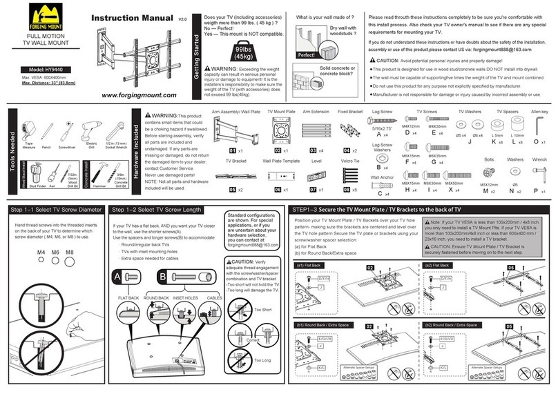
Parts and Hardware
WARNING: This product contains small items that could be a
choking hazard if swallowed. Before starting assembly, verify all parts
are included and undamaged. If any parts are missing or damaged, do
not return the damaged item to your dealer; contact Customer Service.
Never use damaged parts!
NOTE: Not all hardware included will be used.
TV Screws
TV Screws
Washers
Spacers
Wall Plate
Wood Screws (Wall Plate Screws)
Washers
Driver Bit (Square)
Stando**
(Magnetic Leveling Feet)
Disc
(Adhesive backed)
** WARNING: This product contains a magnet. If an implanted
medical device such as a pacemaker or implantable cardioverter defibrillator
(ICD) is in use, magnetic fields may aect the operation of those devices,
resulting in serious injury or death. If you have an implanted medical device,
keep at least 13 cm (5 in.) between your device and the magnet. Please consult
with your physician or medical professional prior to using this product.
Parts and Hardware for STEP 1
Parts and Hardware for STEP 2
Parts for STEP 3 (OPTIONAL)
*For concrete installations:
Contact customer service at
1-888-333-9952 to have these
anchors shipped directly to you.
Concrete Anchor Kit CMK3 (NOT INCLUDED)
Fischer UX8x50R Anchor
2-1BVerify Your Wall 2-2BAttach the Wall Plate
CONCRETE OPTION 2B
Min.
8 in.
(203 mm)
Min. 8 in.
(203 mm)
Min. 16 in.
(406 mm)
Position wall plate 15 at your
desired height. Level, then mark
the two hole locations.
Drill two pilot holes using a 5/16 in.
(8 mm) masonry drill bit.
IMPORTANT: Pilot holes must be
drilled to a depth of 2.75 in. (70 mm).
Never drill into the mortar between blocks.
Insert two anchors C1(Fischer UX8x50R
included in Concrete Anchor Kit CMK3*).
CAUTION: Be sure the anchors are
seated flush with the concrete surface.
Install wall plate 15 with two washers 17 and
screws 18 , using bit 16 .
Securely tighten both screws 18 .
CAUTION: Improper use could reduce the holding
power of screws 18 . DO NOT over-tighten the screws.
Install wall plate 15 with two washers 17 and
screws 18 , using bit 16 .
Adjust leveling, if necessary, then securely tighten
both screws 18 .
CAUTION: Improper use could reduce the holding
power of screws 18 . DO NOT over-tighten the screws.
CAUTION: Avoid potential personal injuries and
property damage!
●Minimum solid concrete thickness: 8 in. (203 mm)
●Minimum concrete block size: 8 x 8 x 16 in. (203 x 203 x 406 mm)
●Minimum horizontal space between fasteners: 16 in. (406 mm)
●Mount wall plate 15 directly onto the concrete surface
Attach Wall Plate to Wall
CAUTION: Avoid potential personal injuries and
property damage!
●Drywall covering the wall must not exceed 5/8 in. (16 mm)
●Minimum wood stud size: common 2 x 4 in. (51 x 102 mm)
nominal 1½ x 3½ in. (38 x 89 mm)
●Minimum horizontal space between fasteners: 16 in. (406 mm)
●Stud centers must be verified – not all walls have
conventional 16 in. (406 mm)
2-2AFind the Stud Centers
2-1AVerify Your Wall 2-3AAttach the Wall Plate
Locate the
studs using a
stud finder.
Probe the wall
with an awl or
drill bit to verify
the stud edges.
Mark the
center of
both studs.
WOOD STUD OPTION 2A
Max.
5/8 in.
(16 mm)
Min. 16 in.
(406 mm)
Min. 1 1/2 in. (38 mm)
Min. 3 1/2 in. (89 mm)
CAUTION: Verify thread engagment of the
screw or spacer/screw combination in STEP 1-2.
— Too short will not hold the TV
— Too long will damage the TV.
Too
Short
Correct Correct
Too
Long
Attach TV Bracket to TV
1-1 Select Your TV Screws 1-2 Attach the TV Bracket
• Flat Back TV [AND TV closer to the wall] • Rounded Back TV
• Extra Space Needed [for cables or inset holes]
Center TV bracket 01 on your TV's hole pattern and securely attach using hardware configuration Aor B,depending on your TV needs.
Inset
Holes
Cables
Position wall plate 15 at
your desired height. Level,
then mark the two hole
locations.
Drill two pilot holes using a
1/8 in. (3.2 mm) drill bit.
IMPORTANT: Pilot holes
must be drilled to a depth of
2.5 in. (63 mm).
01
x1
15
x1
02
x2
03
x2
14
x2
04
x2
05
x2
06
x2
07
x2
08
x2
09
x2
13
x2
12
x2
11
x2
17
x2 18
x2
19
x2
20
x2
16
x1
10
x2
A B
