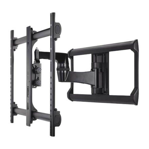
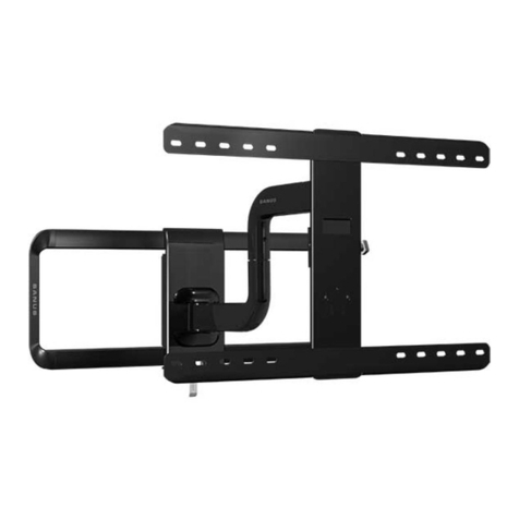
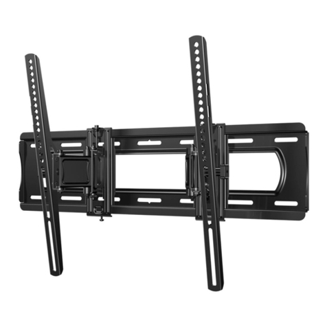
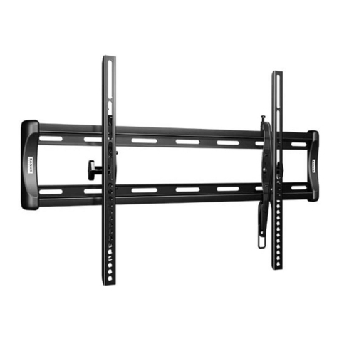
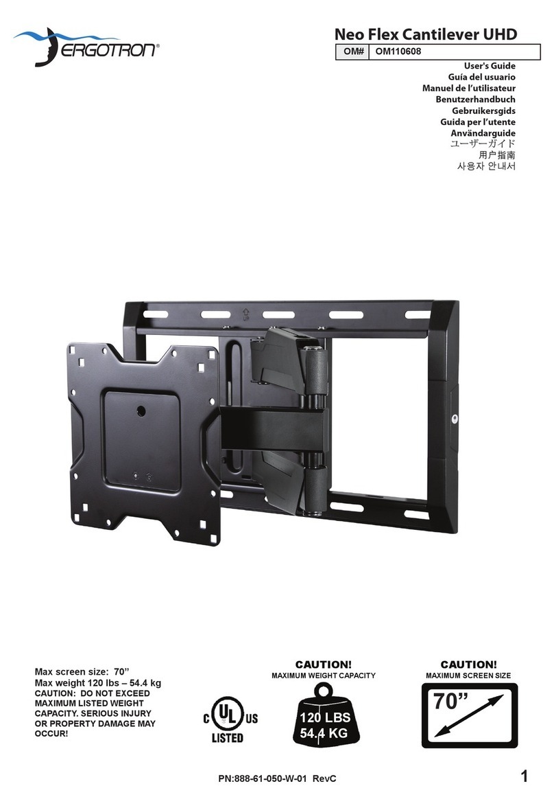
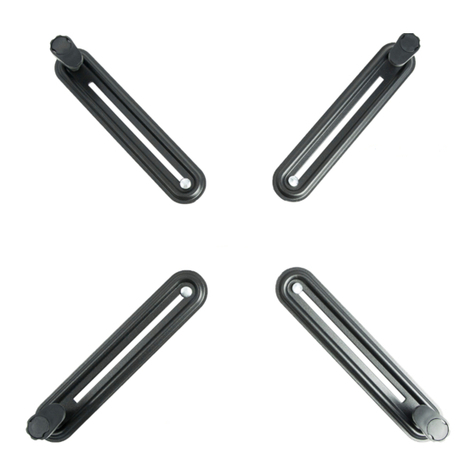
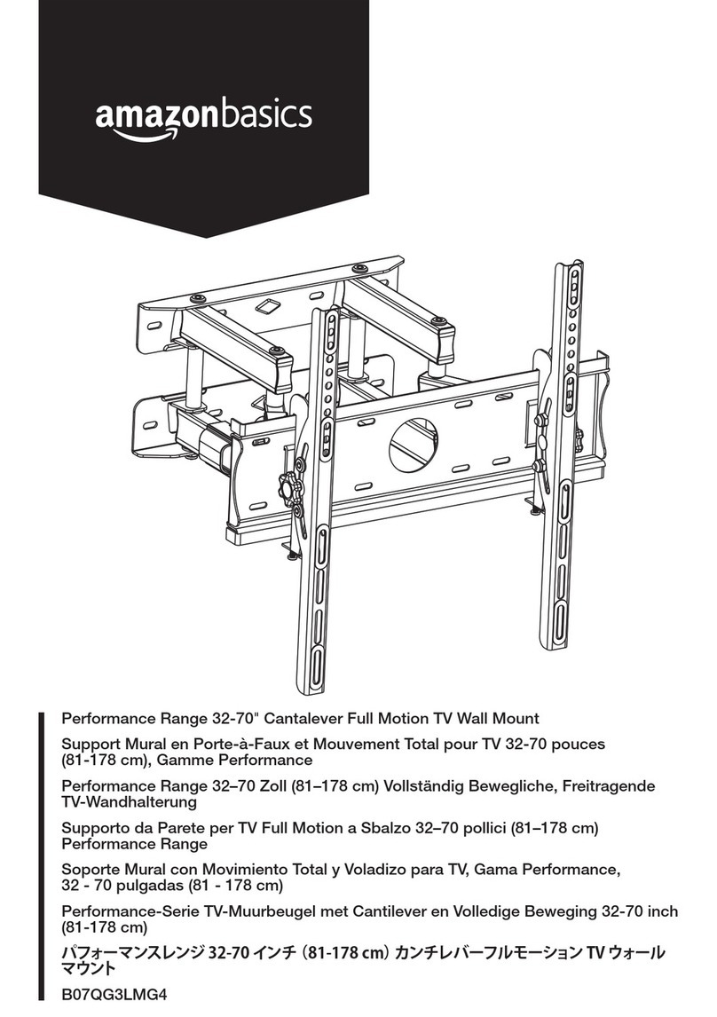
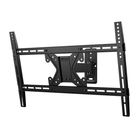
Sanus SLF428-B2 User manual

WE’RE HERE TO HELP
Our US-based install experts
are standing by to help.
Get it right the first time.
HeightFinder™ shows you
where to drill.
Check it out at:
SANUS.com/2692
Want to watch a video that
shows how easy this DIY
project will be?
Watch it now at:
SANUS.com/3025
Call us at:
US: +1 (888) 333-1376
EMEA: +31 (0) 495 580 852
UK: +44 (0) 800 056 2853
SLF
428-B2
INSTRUCTION MANUAL
Texto en Español, página 14
Texte Français page 16
Texti á Íslensku á bls. 18
BEFORE MOUNTING YOUR TV
Record your TV information and
save for future reference.
Or, take a photo of your TV product
sticker and save for future reference.
Brand:
Model No.:
Serial No. (S/N):
Version/SCC/Other:
Your TV product sticker may be inaccessible after mounting your TV.

2
IMPORTANT SAFETY INSTRUCTIONS
– PLEASE READ MANUAL PRIOR TO USE – SAVE THESE INSTRUCTIONS
CAUTION: Avoid potential personal injuries and property damage!
●This product is designed ONLY to be installed into wood studs, solid concrete or concrete block
—DO NOT INSTALL INTO DRYWALL ALONE — DRYWALL ALONE WILL NOT HOLD THE WEIGHT OF YOUR TV
●This product is designed for INDOOR USE ONLY
●The wall must be capable of supporting five times the weight of the TV and mount combined
●Do not use this product for any purpose not explicitly specified by manufacturer
●Manufacturer is not responsible for damage or injury caused by incorrect assembly or use
Please read through these instructions completely to be sure you’re comfortable with this easy install process.
Check your TV owner’s manual to see if there are any special requirements for mounting your TV.
If you do not understand these instructions or have doubts about the safety of the installation, assembly or use of this product, contact Customer Service, at
US: +1 (888) 333-1376 ●EMEA: +31 (0) 495 580 852 ●UK: +44 (0) 800 056 2853.
Tools Needed
Wall
Construction
ONLY install on
these acceptable
wall types. Drywall alone
will NOT hold the
weight of your TV.
wood studs Solid concrete or
concrete block
ACCEPTABLE ACCEPTABLE
CAUTION:
DO NOT install
in drywall alone
135 lbs.
(61.2 kg)
TV Weight Limit
(including accessories)
DO NOT EXCEED
If your TV (plus accessories) weighs MORE, this
mount is NOT compatible.
Visit Preferred.SANUS.com or call customer service to
find a compatible mount.
Wood Stud Install
Concrete Install
Awl
Pencil Level Tape
Stud
Finder
ScrewdriverTape
Measure
5.5 mm
(7/32 in.)
Wood
Drill Bit
Electric
Drill
Hammer
13 mm
(1/2 in.)
Socket
Wrench
Drill Bit
10 mm
(3/8 in.)
Concrete
Call Customer Service
US: +1 (888) 333-1376
EMEA: +31 (0) 495 580 852
UK: +44 (0) 800 056 2853
Unsure

3
Dimensions
28.0in
712mm
15deg
4deg
23.6in
600mm
MAX VESA
15.7in
400mm
MAX VESA
3.9in
100mm
MIN VESA
16.0in
406mm
24.0in
610mm
12.7in
322mm
10.8in
274mm
25.3in
643mm
17.3in
439mm
28.6in
726mm
2.4in
62mm
7.4in
188mm
OFFSET
14.8in
376mm
OFFSET
70deg
70 deg
SIMULATED 42"
FLAT SCREEN TV
TV INTERFACE
WALL PLATE
TOP VIEW - EXTENDED
3-D
SIDE VIEW - EXTENDED
SIDE VIEW RETRACTED
TOP VIEW - RETRACTED
FULLY ASSEMBLED MOUNT
3.9in
100mm
MIN VESA
BEFORE YOU BEGIN
Remove the stand
from your TV —if attached.
Install any accessories
you may have purchased, if they requireTV
removal prior to assembly. The TV is removable
for future accessory purchases.
Soft clean surface
Protect the face
of your TV when laying it down for
installation.

4
1/4-20 x 1 in.
2.5mm
22mm
M6 x 20mmM6 x 12mm
M4 x 12mm
M6 x 35mm
M4 x 35mm
M5 x 11mm
5mm
10-32 x 3/8 in.
10-24 x 1/2 in.
M8 x 50mm
M8 x 16mm
M8 x 20mm
M8 x 30mm
M8 x 40mm
3/16 in.
5/16 x 3 ½ in.
Washers
(x 4 each)
03
02
01
M4
M4
M6/M8
M4/M6/M8
M6
M8
05
WARNING: This product contains small items that could be a choking hazard if swallowed. Before starting assembly, verify all parts are included and undamaged. If any parts are missing or damaged, do
not return the damaged item to your dealer; contact Customer Service. Never use damaged parts!
Supplied Parts and Hardware
TV Screws (x 4 each)
[Only one size fits your TV] Spacers
(x 4 each)
[If necessary]
TV Bracket
Horizontal
TV Bracket
Vertical
M5 x 11MM
SCREW
06
(x 2)
04
STEP 3
STEP 1
1/4-20 x 1 in.
2.5mm
22mm
M6 x 20mmM6 x 12mm
M4 x 12mm
M6 x 35mm
M4 x 35mm
M5 x 11mm
5mm
10-32 x 3/8 in.
10-24 x 1/2 in.
M8 x 50mm
M8 x 16mm
M8 x 20mm
M8 x 30mm
M8 x 40mm
3/16 in.
5/16 x 3 ½ in.
Concrete Anchor
Arm Assembly
CAUTION: Do not use in drywall or wood.
1/4" x 1" Screw #10 x 3/8" Screw
Hex Key
12 13 14
07
08
#10 x 1/2" Screw
Lag Screw
Drilling Template
Wall Plate
09
10
15
11
For concrete installations ONLY
(x 1)
(x 4)
(x 1)
(x 1)
(x 4)
(x 4)
(x 2) (x 2) (x 1)
(x 1)
(x 1)
STEP 2
NOTE: Not all hardware included will be used.

5
• Flat Back TV
[TV brackets 04 lay flat on your TV]
NO SPACER SPACER NEEDED
AB
Only one screw size fits your TV.
M4 M6 M8
01
Use short TV screws 01 .
Spacers 03 not needed.
STEP 1 Attach TV Bracket to TV
Use long TV screws 01 and spacers 03 to create extra space
between the TV and TV bracket.
• Flat Back TV with extra space needed
[for deep inset holes or cable interference]
• Rounded or Irregular Back TV
[TV brackets 04 NOT resting flat on your TV]
CAUTION: Verify adequate thread engagement with your screw 01 , washer 02 ,
spacer 03 combination AND TV bracket 04 .
— Too short will not hold your TV. — Too long will damage your TV.
1.2 Select TV Screw Length and Spacers1.1 Select TV Screw Diameter
NOTE: If your TV
included inset spacers or
adapters, use them UNDER
the mount hardware.
1.3 Attach TV Brackets to Your TV
1
04
04
2
04
02 01
ANO SPACER
06
04 05
06
05
02
01
BSPACER NEEDED
03
CAUTION: Avoid potential personal injuries and property damage! DO NOT use power tools for this step. Tighten the screws 01 and 06 only enough to secure the TV
brackets to the TV.

6
STEP 2A Attach Wall Plate
12
Min.
16 in.
(406 mm)
Max.
5/8 in. (16 mm)
07
CAUTION: Avoid potential personal injury or property damage!
●Drywall covering the wall must not exceed 5/8 in. (16 mm)
●Minimum wood stud size: nominal 2 x 4 in. (51 x 102 mm) actual 1½ x 3½ in. (38 x 89 mm)
●Minimum spacing between studs: 16 in. (406mm)
●Stud center must be verified
Wood Stud Installation
09
3 4
3 ½in. (9 cm)
7/32 in.
(5.5 mm)
07
08
IMPORTANT: Be sure to drill into the center of the stud. CAUTION: Avoid potential personal injury or property damage!
Improper use could reduce the holding power of the lag bolt 09 .
Tighten the lag bolts 09 only until they are pulled FIRMLY against the
wall plate 08 .
DO NOT over-tighten the lag bolts 09 .
Go to STEP 3 on PAGE 8.

7
1 2
3/8 in.
(10 mm)
3 ¾ in. (9.5 cm)
002862.eps
07 07
CAUTION: Avoid potential personal injury or property damage!
●Mount wall plate
08
directly onto concrete surface (no wall covering)
●Minimum solid concrete thickness: 8 in. (203 mm)
●Minimum concrete block size: 8 x 8 x 16 in. (203 x 203 x 406 mm)
●For concrete applications, arm assembly
11
(STEP 3) must remain centered in wall plate
08
.
Keep this in mind when selecting wall plate location
●Install lag bolts
09
in slots AS SHOWN. Three (3) lag bolts
09
on top. One (1) lag lag bolt
09
on bottom.
Solid Concrete or Concrete Block Installation
STEP 2B Attach Wall Plate
34
CAUTION: Be sure the anchors 10 are seated flush with the
concrete surface.
CAUTION: Never drill into the mortar between blocks.
08
CAUTION: Avoid potential personal injury or property damage!
Improper use could reduce the holding power of the lag bolt 09 .
Tighten the lag bolts 09 only until they are pulled FIRMLY against the
wall plate 08 .
DO NOT over-tighten the lag bolts 09 .
3x
1x
CAUTION: Avoid potential personal injury or property damage!
Install three (3) lag bolts
09
at the top and one (1) lag bolt
09
at the bottom.
09
10

8
11
11
08
08
08
11
3.1 Attach Arm Assembly to Wall Plate
STEP 3 Hang TV onto Wall Plate
HEAVY! You may need assistance with this step.
13
NOTE: For WOOD STUD APPLICATIONS,the arm
assembly 11 can be slid anywhere along wall plate 08 for
optimal positioning of your TV.
CAUTION: Avoid potential personal injury or property damage!
For CONCRETE APPLICATIONS:
The arm assembly 11 MUST remain centered in wall plate 08 .
1
3
2
4
11
08

9
08
3.1 Attach Arm Assembly to Wall Plate
STEP 3 Hang TV onto Wall Plate
12
15
13
12 15
Firmly tighten screws 13 .
Firmly tighten screws 12 .
5
7
6
8

10
1
1. Remove the cable covers C.
IMPORTANT:Fully extend arm assembly 11 to ensure enough slack in cables.
2. Route your cables through the arm assembly 11 shown —to avoid pinching.
3. Reattach the cable covers Cover the cables.
3
2
CC
C
C11
Manage Cables
123
05
11
11
05
CAUTION: Avoid potential personal
injury or property damage! Locking
screw 14 must be installed to secure the
TV to the arm assembly 11 .
3.2 Attach TV to Arm Assembly HEAVY! You may need assistance with this step.
05
11
15
14
CC

11
Your TV should adjust easily when moved, then stay in place. If your TV is too loose or too tight, adjust the side tension knob Tby hand or
use hex key 15 for additional tightening.
NOTE: Once your TV is in place, tighten the tension knob Tto prevent unwanted movement.
NOTE: Additional tension can be applied using hex key 15 .
1. Loosen screw 14 . 3. Retighten screw 14 .
2. Adjust the leveling of your TV by
turning the level screw L.
14 14
TILT ADJUSTMENT
LEVEL ADJUSTMENT
TV Adjustments
CAUTION:
Screw 14 MUST be loosened
before turning screw L.
15
T
L

12
1. Remove your TV (PAGE 13).
2. Open the cover plates and remove two
screws 12 and two screws 13 to
release arm assembly 11 .
3. Reposition the arm assembly 11 on
the wall plate (STEP 3.1).
3
2a
1a2b
2c
1b
5b
5a
4b
4a
LATERAL SHIFT HEAVY! You may need assistance with this step.
CAUTION:
Avoid potential injuries or property damage!
DO NOT adjust the arm 11 position from center for CONCRETE APPLICATIONS.
Arm 11 MUST remain centered in wall plate 08 for all concrete applications!
4. Reattach the two screws 12 and
two screws 13 (STEP 3.1) and
close the cover plates.
5. Hang your TV onto the arm
assembly 11 following STEP 3.2.
For WOOD STUD APPLICATIONS,
15
15
13
13
08
08
11
11
12
12

13
1 2
3 4
REMOVING THE TV HEAVY! You may need assistance with this step.
05
Your TV should adjust easily when moved, then stay in place. ONLY if needed, adjust the
extension/retraction arm tension with screw Rusing a 1/8 inch hex key (not supplied).
CAUTION: Avoid potential personal injury or property damage!
DO NOT remove bolts R,only turn enough for slight adjustment.
EXTEND / RETRACT -- ONLY IF NECESSARY
R
15
14
15
11
05

14
herramientas
necesarias
Montantes
de Madera
Montantes
de Cemento
Punzón
Lápiz Nivel Cinta
Adhesiva
Localizador de
montantes
DestornilladorCinta
métrica Broca
Taladro
eléctrico Martillo
Llave de
vaso Broca
10 mm
(3/8'')
Hormigón
13 mm
( 1/2 pulgada)
5,5 mm
(7/32 pulgadas)
Madera
Llame al Servicio de Atención al Cliente US: +1 (888) 333-1376
EMEA: +31 (0) 495 580 852 ●Reino Unido: +44 (0) 800 056 2853
La construcción de su pared
SOLAMENTE instalar en estos tipos
aceptables de la pared.
Instalación en panels de
yeso solo NO soportará el
peso de su TV.
¿No está seguro?
Montantes de madera Hormigón macizo o bloque
de hormigón
ACEPTABLE ACEPTABLE
PRECAUCIÓN:
NO lo instale
en paredes
únicamente
de yeso
61,2 kg
(135 lbs.)
Lea atentamente estas instrucciones en su totalidad para asegurarse de que está familiarizado con el sencillo proceso de instalación.
Consulte igualmente el manual de su televisor para conocer si existen requisitos especiales para el montaje de su aparato.
Si no entiende las instrucciones o si tiene dudas acerca de la seguridad de la instalación, el montaje o el uso del producto, póngase en contacto con el Servicio de Atención al
Cliente o llame a nuestro servicio técnico al número US: +1 (888) 333-1376 ●EMEA: +31 (0) 495 580 852 ●Reino Unido: +44 (0) 800 056 2853.
PRECAUCIÓN: Evite posibles lesiones personales y daños materiales.
●Este producto se ha diseñado para su uso en montantes de madera, hormigón macizo y paredes de bloques de hormigón:
NO lo instale en paredes únicamente de yeso
●La pared debe ser capaz de soportar hasta cinco veces el peso combinado del televisor y la montura
●No utilice este producto para ningún otro propósito que no sea el explícitamente especificado por el fabricante
●El fabricante no se responsabiliza de ningún daño o lesión resultante del montaje incorrecto o el uso indebido
Peso máximo (incluidos los accesorios)
NO EXCEDAS
Si su TV (incluidos los accesorios) pesa MÁS, esta soporte NO es compatible. Visite
Preferred.SANUS.com o llame al número US: +1 (888) 333-1376 ●EMEA: +31 (0) 495 580 852
ReinoUnido:+44(0)800056 2853 paraencontrarunamonturacompatible.
INSTRUCCIONES IMPORTANTES DE SEGURIDAD LEA TODO ESTE MANUAL ANTES DE UTILIZAR ESTE PRODUCTO GUARDE ESTAS INSTRUCCIONES
ESPAÑOL
SOLO para instalaciones en hormigón
PRECAUCIÓN: No se debe utilizar en paredes de yeso ni de madera UX10 x 60R
10 x4
Piezas y herramientas suministrados
Dimensiones
VER PÁGINAS 4
VER PÁGINA 3
PASO 1 Fijar el soporte al televisor VER PÁGINA 5
Utilice los tornillos del televisor cortos 01 .No
hacen falta espaciadores 03 .
Utilice los tornillos del televisor largos 01 y los espaciadores 03 para crear espacio
adicional entre el televisor y el soporte.
ADVERTENCIA: Este producto contiene piezas pequeñas que, en caso de ser tragadas, podrían causar asfixia. Antes de comenzar a montar la unidad, verifique que dispone de todas
las piezas y que se encuentran en buen estado. Si no dispone de todas las piezas o alguna está dañada, no devuelva el elemento defectuoso al distribuidor. Póngase en contacto con el
Servicio de Atención al Cliente. Nunca utilice piezas en mal estado. NOTA: No se utilizarán todos los elementos de sujeción incluidos.
Solo hay un tamaño de tornillo que funcione para su televisor.
1,1 Diámetro de los tornillos del televisor
1,2 Longitud de los tornillos del televisor
• Televisor con parte posterior plana
[Los soportes del televisor 04 se apoyan de manera plana en él]
SIN ESPACIADOR CON ESPACIADOR
• Televisor con parte posterior plana
con necesidad de espacio adicional
[para orificios empotrados o interferencia de cables]
• Televisores con parte posterior redonda o irregular
[Los soportes del televisor 04 NO se apoyan de manera plana en él]
A B
NOTA: Si su televisor incluye espaciadores empotrados o adaptadores para soportes de pared, úselos BAJO el hardware de montaje.
Antes de comenzar
Retire el soporte de su televisor... ¡si ya estaba instalado claro!
Instale cualquier accesorio que quiera añadir a su televisor. Consulte todos los manuales de instalación de los accesorios para determinar si necesita INSTALARLOS ANTES de montar su televisor.
Proteja la pantalla de su televisor cuando lo tumbe para la instalación.
Anote la información de su TV y guárdela para futuras consultas.
También puede tomar una fotografía de la pegatina del producto de su TV y guardarla para futuras consultas.
La pegatina del producto de su TV puede ser inaccesible después de montarlo. ANTES DE MONTAR SU TV.
Ver portada

15
PRECAUCIÓN: Verifique que el tornillo o la combinación de tornillo 01 , arandelas 02 , espaciador 03 y placas de sujeción del televisor 04 enrosquen
correctamente. Si el tornillo es demasiado corto no sostendrá el televisor. Si es demasiado largo dañará el televisor.
PRECAUCIÓN: Evite lesiones personales y daños materiales.
●Los paneles de yeso que cubren la pared no deben superar los 16 mm (5/8 pulg.)
●Tamaño mínimo de los montantes de madera: nominal 51 x 102 mm (2 x 4 pulg.) actual 38 x 89 mm (1½ x 3½ pulg.)
●Espacio mínimo entre los elementos de sujeción: 406 mm (16 pulg.)
●Se debe verificar el centro del montante
IMPORTANTE:Asegúrese de taladrar en el centro del montante.
PRECAUCIÓN: El uso indebido podría reducir la capacidad de retención de los tornillos tirafondo 09 . Ajuste los pernos tirafondo 09 solamente hasta que queden firmes contra la placa mural 08 .
NO ajuste en exceso los tornillos tirafondo.
PRECAUCIÓN: Evite lesiones personales y daños materiales.
●Instale la placa mural 08 directamente sobre la superficie de hormigón
●Grosor mínimo del hormigón macizo: 203 mm (8 pulg.)
●Tamaño mínimo del bloque de hormigón: 203 x 203 x 406 mm (8 x 8x 16pulg.)
●Para aplicaciones sobre hormigón, el brazo 11 (PASO 3) debe permanecer centrado en la placa de pared 08 . Téngalo en cuenta a la hora de seleccionar la ubicación de la placa de pared
●Instale los pernos tirafondo 09 en las ranuras COMO SE MUESTRA. Tres (3) pernos tirafondo 09 en la parte superior. Un (1) perno tirafondo 09 de retardo en la parte inferior
PASO 2A Fijar la placa de pared
PASO 2B Fijar la placa de pared
Colocación sobre montantes de madera
Instalación en hormigón macizo o bloque de hormigón
VER PÁGINA 6
VER PÁGINA 7
1,3 Fije el soporte del televisor
PRECAUCIÓN: Instale los pernos tirafondo 09 en las ranuras COMO SE MUESTRA. Tres (3) pernos tirafondo 09 en la parte superior. Un (1) perno tirafondo 09 de retardo en la parte inferior.
PRECAUCIÓN: Nunca taladre sobre el cemento entre los bloques.
PRECAUCIÓN: Asegúrese de que los anclajes para hormigón 10 . estén nivelados con la superficie de hormigón.
PRECAUCIÓN: El uso indebido podría reducir la capacidad de retención de los tornillos tirafondo 09 . Ajuste los pernos tirafondo 09 solamente hasta que queden firmes contra la placa mural 08 .
NO ajuste en exceso los tornillos tirafondo.
PASO 3 Fije el televisor a la montaje del brazo VER PÁGINA 8
PRECAUCIÓN: Evite posibles lesiones personales y daños materiales. NO use herramientas eléctricas para este paso. Apriete los tornillos 01 y 06 con la fuerza adecuada para fijar el soporte del televisor al aparato.
¡PRODUCTO PESADO! Podría necesitar ayuda
para realizar esta operación.
Organizar los cables
Ajustes del televisor
1. Retire la cubierta de los cables C. IMPORTANTE:Extienda el brazo 11 por completo antes de pasar los cables. 2. Pase los cables por el brazo 11 .3. Vuelva a colocar la cubierta de los cables Cpor sobre los cables.
VER PÁGINA 11
VER PÁGINA 10
AJUSTE DE LA INCLINACIÓN
AJUSTE DEL NIVEL
CÓMO RETIRAR EL TELEVISOR
1. Afloje el tornillo 14 . 2. Ajuste el nivel de su televisor girando el tornillo Lde ajuste de nivel. 3. Apriete el tornillo 14 .
El televisor debe acomodarse fácilmente al moverlo, y luego quedar en su lugar. Si el televisor está demasiado suelto o demasiado ajustado, ajuste la perilla de tensión lateral Tmanualmente.
NOTA: Una vez que el televisor esté en su lugar, ajuste las perillas de tensión Tpara evitar un movimiento indeseado. NOTA: se puede aplicar tensión adicional usando una llave hexagonal de 3/16 de pulgada 15 .
¡PRODUCTO PESADO! Podría necesitar ayuda para realizar esta operación.
PRECAUCIÓN: El tornillo 14 DEBE aflojarse antes de girar el tornillo L.
EXTIENDA O RETRAIGA
El televisor debe acomodarse fácilmente al moverlo, y luego quedar en su lugar. Si el televisor está demasiado suelto o demasiado ajustado, ajuste el tornillo Rusando una llave hexagonal de 1/8 de pulgada (no incluida).
PRECAUCIÓN: Evite posibles lesiones personales o daños materiales. NO quite el tornillo R,solo girar suficiente para un ligero ajuste.
DESPLAZAMIENTO LATERAL DEL TELEVISOR
1. Quite el televisor del montaje del brazo 11 (ver PÁGINA 13). 2. Abrir las cubiertas y quite los dos tornillos 12 y los dos tornillos 13 para liberar el conjunto del brazo 11 . 3. Vuelva a posicionar el montaje del brazo
11 en la placa de pared. 4. Vuelva a fijar los dos tornillos 12 y los dos tornillos 13 (ver PASO 3.1) y vuelva a colocar las cubiertas. 5. Cuelgue el televisor en el montaje del brazo 11 de acuerdo con las instrucciones
descritas en el PASO 3.2.
PRECAUCIÓN:Evite posibles lesiones personales y daños materiales. NO ajuste el brazo desde el centro cuando esté colocado sobre hormigón. La base del brazo 11 DEBE mantenerse centrada en la placa de pared
08 cuando el soporte se encuentre colocado en paredes de hormigón.
¡ELEMENTO PESADO! Es posible que necesite ayuda en este paso.
3,2 Acoplar el televisor al módulo del brazo
3,1 Fijar el módulo del brazo a la placa mural VER PÁGINA 8
VER PÁGINA 10
PRECAUCIÓN: Evite el riesgo de lesiones y daños materiales. Este tornillo 14 debe instalarse para fijar el televisor al ensamblaje del brazo 11 .
PRECAUCIÓN: Evite posibles lesiones personales o daños materiales. Para APLICACIONES DE HORMIGÓN: El conjunto del brazo 11 DEBE permanecer centrado en la placa mural 08 .
NOTA: Para APLICACIONES SOBRE MONTANTES DE MADERA, el conjunto del brazo 11 se puede deslizar a cualquier parte de la placa mural 08 para conseguir colocar su
televisor en una posición óptima.
Apriete firmemente los tornillos 13 y 12 .
VER PÁGINA 11
VER PÁGINA 11
VER PÁGINA 12
VER PÁGINA 13
VER PÁGINA 13

16
Français
Outil
nécessaire
Appelez au US: +1 (888) 333-13760
EMEA: +31 (0) 495 580 852 ●RU: +44 (0) 800 056 2853
La construcción de su pared
Vous avez des doutes?
montants en bois Béton coulé ou
blocs de béton
ACCEPTABLE ACCEPTABLE
ATTENTION!
NE PAS
fixer sur
unecloisonsèche
seule
61,2 kg
(135 lbs)
Veuillez lire au complet ces instructions pour vous assurer d’être à l’aise avec ce processus d’installation facile. Veuillez également consulter le manuel du propriétaire de
votre téléviseur pour savoir si son installation présente des exigences particulières.
Si vous ne comprenez pas toutes ces instructions ou si vous avez des doutes sur la sécurité de l’installation, du montage ou de l’utilisation de ce produit, veuillez
contacter le service à la clientèle au US: +1 (888) 333-1376 ●EMEA: +31 (0) 495 580 852 ●RU: +44 (0) 800 056 2853 .
ATTENTION : Évitez les risques de blessures corporelles ou de dommages matériels !
●Ce produit est conçu pour une utilisation sur des montants porteurs en bois, des murs en béton solide et en bloc de béton -
Ne l’installez PAS seul sur une cloison sèche.
●Le mur doit pouvoir supporter cinq fois le poids total du téléviseur et du support.
●N’utilisez pas ce produit à d’autres fins que celles spécifiées par le fabricant.
●Le fabricant n’est pas responsable des blessures ou des dommages causés par une mauvaise utilisation ou un montage incorrect.
Poids limite (avec les accessoires)
NE PAS DÉPASSER
Si votre téléviseur (avec les accessoires) pèse plus, Ce support n’est PAS compatible.
Visitez Preferred.SANUS.com ou composez le US: +1 (888) 333-1376
●EMEA: +31 (0) 495 580 852 ●RU: +44 (0) 800 056 2853
pour trouver un support compatible.
INFORMATIONSIMPORTANTESCONCERNANTLASÉCURITÉ–CONSERVEZ CESINSTRUCTIONS–VEUILLEZ LIRE ATTENTIVEMENTLEMANUELAVANTD’UTILISER CE PRODUIT
13 mm
(1/2 po)
5,5 mm
(7/32 po)
Bois
10 mm
(3/32 po)
Béton
Tournevis
Ruban à
mesurer ForetForet
Perceuse
électrique MarteauClé à douilles Localisateur de
montants Alêne
Crayon Niveau
Structure de murs
en bois
Murs en béton coulé
Ruban
adhésif
Installez UNIQUEMENT sur ces types de
murs acceptables.
Pièces et quincaillerie fournies
Dimensions
PAGE 4
PAGE 3
ÉTAPE 1 Fixez la patte de fixation sur le téléviseur
1,1 Sélectionnez le diamètre des vis pour le téléviseur
PAGE 5
1,2 Sélectionnez la longueur de vis et les entretoises pour le téléviseur
Utilisez des vis courtes de téléviseur 01 .
Les entretoises 03 ne sont pas nécessaires.
Utilisez des vis longues de téléviseur 01 et les entretoises 03 pour créer un
espace supplémentaire entre le téléviseur et la patte de fixation.
AVERTISSEMENT : Ce produit contient de petites pièces qui peuvent représenter un risque d’étouffement si elles sont avalées. Avant de commencer l’assemblage, assurez-vous que toutes les pièces
sont présentes et qu’elles ne sont pas endommagées. Si une pièce est manquante ou endommagée, contactez le service à la clientèle et non le détaillant. N’utilisez jamais de pièces endommagées!
REMARQUE : les pièces fournies ne doivent pas nécessairement être toutes utilisées. UNIQUEMENT pour les installations sur un mur en béton
ATTENTION : ne l'utilisez pas sur une cloison sèche ou en bois
UX10 x 60R
10 x4
Seule une taille de vis s'adapte à votre téléviseur.
• Téléviseur à dos plat
[Les pattes de fixation 04 reposent à plat sur votre téléviseur]
PAS D’ENTRETOISE ENTRETOISE NÉCESSAIRE
• Téléviseur à dos plat avec espace supplémentaire nécessaire
[pour les trous d'insertion profonds ou les interférences de câble]
• Téléviseur à l’arrière arrondi ou irrégulier
[Les pattes de fixation 04 ne reposent PAS à plat sur votre téléviseur]
A B
REMARQUE: Utilisez l'entretoise destinée aux téléviseurs à dos plat fournie avec le téléviseur.
Avant de commencer
Retirez le socle de votre téléviseur ... s’il est installé bien sûr.
Installez tout accessoire que vous prévoyez d’ajouter à votre téléviseur. Vérifiez les manuels d’installation de tous les accessoires pour savoir si vous devez les INSTALLER AVANT de monter votre téléviseur.
Protégez la face de votre téléviseur lorsque vous le poserez pour l’installation.
Notez les informations concernant votre télévision et conservez ces notes pour toute consultation ultérieure.
Sinon, prenez l’étiquette produit de votre télévision en photo et conservez la photo pour toute consultation ultérieure.
L'étiquette produit de votre télévision pourrait ne plus être accessible après le montage de votre télévision. AVANT LE MONTAGE DE VOTRE TÉLÉVISION.
Voir la
couverture
ATTENTION : Assurez-vous que la longueur du filetage de la combinaison vis 01 , rondelle 02 , entretoise 03 ET de la patte de fixation pour téléviseur 04 est correcte.
—Si elle est insuisante, il sera impossible de maintenir le téléviseur. —Si elle est excessive, le téléviseur sera endommagé.

17
ATTENTION : évitez les risques de blessures corporelles ou de dommages matériels!
●L’épaisseur du revêtement de cloison sèche ne doit pas excéder 16mm (5/8po)
●Taille minimum des montants de bois: nominale 51 x 102 mm (2 x 4 po), habituelle 38 x 89 mm (1 ½ x 3 ½ po)
●Espace minimum entre les fixations : 406 mm (16 po)
●Le centre du montant doit être vérifié
ATTENTION : évitez les risques de blessures corporelles ou de dommages matériels!
●Montez l'ensemble de la plaque murale 08 directement sur la surface de béton
●Épaisseur minimale du béton plein: 203mm (8po)
●Dimension minimale du bloc de béton: 203 x 203 x 406 mm (8 x 8 x 16 po)
●Pour les utilisations sur béton, le bras 11 (ÉTAPE 3) doit rester centré sur la plaque murale 08 . Gardez ceci à l’esprit lors du choix de l’emplacement de la plaque murale
●Installez des boulons tire-fonds 09 dans les fentes telles qu’indiquées. Trois (3) boulons tire-fonds 09 en haut. Un (1) boulon tire-fond 09 au bas
ÉTAPE 2A Fixez la plaque murale
ÉTAPE 2B Fixez la plaque murale
Installation sur montants en bois
Installation sur béton plein ou blocs de béton
PAGE 6
PAGE 7
1,3 Fixez la patte de fixation pour téléviseur
ATTENTION : Installez des boulons tire-fonds 09 dans les fentes telles qu’indiquées. Trois (3) boulons tire-fonds 09 en haut. Un (1) boulon tire-fond 09 au bas.
ATTENTION : Prenez soin de ne jamais percer dans le mortier entre des blocs.
ATTENTION : Assurez-vous que les chevilles pour béton 10 ne dépassent pas de la surface de béton.
ATTENTION : Évitez les risques de blessures corporelles ou de dommages matériels! Une mauvaise utilisation pourrait réduire la force de maintien du tire-fond 09 .
Serrez les tire-fonds 09 seulement jusqu'à ce qu'ils soient FERMEMENT tirés contre la plaque murale 08 . NE PAS trop serrer les tire-fonds 09 .
ÉTAPE 3 Fixez le téléviseur à la plaque murale LOURD! Vous pourriez avoir besoin de
quelqu’un pour vous aider à cette étape.
LOURD! Vous pourriez avoir besoin de quelqu’un pour vous aider à cette étape.
PAGE 8
ATTENTION : évitez les risques de blessures corporelles ou de dommages matériels! La vis de blocage 14 doit être installée afin de fixer le téléviseur sur l'ensemble de le bras 11 .
ATTENTION : Évitez les risques de blessures corporelles ou de dommages matériels! N'utilisez pas d'outils électriques pour cette étape. Serrez les vis 01 et 06 juste assez pour fixer la patte de
fixation au téléviseur.
ATTENTION: Évitez les risques de blessures corporelles ou de dommages matériels ! Pour les utilisations sur béton, l’ensemble de bras 11 doit rester centré sur la plaque murale 08 .
REMARQUE : Pour les UTILISATIONS SUR DES MONTANTS EN BOIS, l'ensemble du bras 11 peut être glissé tout le long de la plaque murale 08 pour une orientation optimale de votre téléviseur.
Serrez fermement les vis 13 y 12 .
IMPORTANT : assurez-vous de percer au centre du montant.
ATTENTION : évitez les risques de blessures corporelles ou de dommages matériels! Évitez les risques de blessures corporelles ou de dommages matériels! Une mauvaise utilisation pourrait réduire la
force de maintien du tire-fond 09 .
Serrez les tire-fonds 09 seulement jusqu'à ce qu'ils soient FERMEMENT tirés contre la plaque murale 08 . NE PAS trop serrer les tire-fonds 09 .
Gestion des câbles
Réglages du téléviseur
1. Retirez le cache-câble Cdu bras 11 .IMPORTANT : Allongez complètement le bras 11 pour laisser suisamment de jeu et éviter que les câbles soient étirés lorsque les bras sont déplacés.
2. pour éviter de pincer les câbles lorsque vous repliez le bras, acheminez les câbles autour du montant du bras et au travers de l'espace ouvert sur le bras, comme illustré. 3. Replacez le cache-câble C.
PAGE 11
PAGE 10
RÉGLAGE DE L'INCLINAISON
RÉGLAGE DU NIVEAU
RÉ ATTENTION: La vis 14 DOIT être desserée avant de tourner la vis L.GLAGE DU NIVEAU
RETRAIT DU TÉLÉVISEUR
1. Desserrez la vis 14 . 2. Réglez le niveau de votre téléviseur en tournant la vis de mise à niveau L. 3. Resserrez la vis 14 .
Votre téléviseur doit se régler facilement lorsqu'il est déplacé, puis ne doit plus bouger. Si votre téléviseur est trop desserré ou trop serré, réglez manuellement le bouton de tension latéral T. REMARQUE : une fois
votre téléviseur en place, resserrez le bouton de tension latéral Tpour éviter tout mouvement non souhaité. REMARQUE : Vous pouvez appliquer davantage de tension à l’aide d’une clé hexagonale de 3/16 po 15 .
ÉTENDEZ OU REPLIEZ
Votre téléviseur doit se régler facilement lorsqu'il est déplacé, puis ne doit plus bouger. Si votre téléviseur est trop desserré ou trop serré, réglez les vis Ravec une clé hexagonale de 1/8po; (non fournie).
ATTENTION : évitez les risques de blessures corporelles ou de dommages matériels! Ne retirez pas les Vis R.
DÉCALAGE LATÉRAL DU TÉLÉVISEUR
1. Retirez le téléviseur de l'ensemble de bras 11 (voir PAGE 13). 2. Ouvrez les caches et retirez les deux vis 12 et les deux vis 13 pour libérer l'ensemble de bras 11 . 3. Replacez l'ensemble de bras 11 sur la plaque
murale. 4. Fixez à nouveau les deux vis 12 et les deux vis 13 (voir ÉTAPE3.1) et fermez les caches. 5. Accrochez le téléviseur sur l'ensemble de bras 11 en suivant l'ÉTAPE3.2.
ATTENTION :évitez les risques de blessures corporelles ou de dommages matériels! N'AJUSTEZ PAS le bras à partir de la position centrale pour les utilisations sur béton. Pour les utilisations sur béton,
la base du bras 11 DOIT rester centrée dans la plaque murale 08 !
LOURD! Vous pourriez avoir besoin de quelqu’un pour vous aider à cette étape.
3,2 Suspendre le téléviseur au bras
3,1 Fixer le bras à la plaque murale PAGE 8
PAGE 10
PAGE 11
PAGE 11
PAGE 12
PAGE 13
PAGE 13

18
Íslensku
nauðsynleg
verkfæri
Festing í viðarstoð
Festing í stein
Síll
Blýantur Hallamál Stoðaleitari
SkrúfjárnMálband Trébor
Skrúfjárn Hamar
Topplykill Trébor
10 mm
Steinsteypa
13 mm 5.5 mm
Viður
Hringið í þjónustusíma: US: +1 (888) 333-1376
EMEA: +31 (0) 495 580 852 ●Royaume-Uni: +44 (0) 800 056 2853
Veggbygging
Setjið eingöngu á þessar
viðunandi vegggerðir.
Óviss?
Plötum sem festar eru á
viðarstoðir?
Steinsteypu eða
hleðslusteinum úr
steinsteypu?
Fullkomið! Fullkomið!
VARÚÐ:
Festið
vöruna ekki
eingöngu í
veggplötu
61,2 kg
(135 lbs.)
Uppsetningin er auðveld en vinsamlegast lestu leiðbeiningarnar til enda til að vera viss um að þú treystir þér til að framkvæma hana.
Athugaðu líka í notendahandbók sjónvarpsins hvort gerðar eru einhverjar sérkröfur um festingar fyrir sjónvarpið.
Ef þú skilur ekki leiðbeiningarnar eða ert í vafa um öryggi uppsetningarinnar, búnaðarins eða notkun þessarar vöru skalt þú hafa samband við notendaþjónustu í síma
US: +1 (888) 333-1376 ●EMEA: +31 (0) 495 580 852 ●Royaume-Uni: +44 (0) 800 056 2853 .
VARÚÐ: Varist möguleg slys og skemmdir á munum!
●Þessi vara er gerð fyrir festingu í viðarstoðir, steinveggi eða veggi úr hleðslusteini - festið hana EKKI eingöngu í veggplötu
●Veggurinn verður að bera fimm sinnum samanlagðan þunga sjónvarpsins og veggfestingarinnar
●Notið vöruna ekki til annars en þess sem framleiðandi tilgreinir
●Framleiðandi er ekki ábyrgur fyrir skemmdum eða slysum sem verða vegna rangrar uppsetningar eða notkunar
hámarksþyngd (með fylgihlutum)
Ekki fara yfir
Ef sjónvarpið vega meira , Þessi festing hentar EKKI.
Farið á Preferred.SANUS.com eða hringið í US: +1 (888) 333-1376
EMEA: +31 (0) 495 580 852 ●Royaume-Uni: +44 (0) 800 056 2853
til að finna festingu sem hentar.
MIKILVÆGAR ÖRYGGISLEIÐBEININGAR GEYMIÐ ÞESSAR LEIÐBEININGAR VINSAMLEGAST LESIÐ ALLAN BÆKLINGINN FYRIR NOTKUN
Meðfylgjandi íhlutir og járnvörur
Mál
4
3
SKREF 1 Skrúfið sjónvarpsfestinguna á sjónvarpið
1.1 Veljið skrúfustærð fyrir sjónvarpið
5
1.2 Veljið skrúfustærð fyrir sjónvarpið og millistykkin
VARÚÐ: Sannreynið að skrúfurnar grípi nægilega vel með skrúfu 01 , skífu 02 og millistykki 03 samsetningunni OG sjónvarpsbrakketinu 04 .
— Of stuttar halda ekki sjónvarpinu. — Of langar skemma sjónvarpið.
AÐVÖRUN: Vörunni fylgja smáir hlutir sem geta leitt til köfnunar ef þeir eru gleyptir. Athugið að allir
íhlutir séu til staðar og óskemmdir áður en samsetning hefst. Ef einhverja hluti vantar eða þeir eru skemmdir
skalt þú ekki skila þeim til söluaðila heldur hafa samband við notendaþjónustu. Notið aldrei skemmda íhluti!
ATHUGIÐ: Meðfylgjandi hlutir verða ekki allir notaðir.
AÐEINS fyrir festingu í steinvegg
VARÚÐ: Notið ekki fyrir klæðningu eða timbur
UX10 x 60R
10 x4
Aðeins ein skrúfustærð passar fyrir sjónvarpið þitt.
• Sjónvarp með flatri bakhlið
[Festingar fyrir sjónvarp 04 liggja flatar á sjónvarpinu]
ENGINN STÖÐUHÓLKUR STÖÐUHÓLKUR ER NAUÐSYNLEGUR
• Sjónvarp með flatri bakhlið þar sem þörf er á
viðbótarrými [fyrir djúp ísetningargöt eða leiðslur]
• Sjónvarp með ávalri eða ójafnri bakhlið
[Festingar fyrir sjónvarp liggja 04 EKKI flatar á sjónvarpinu]
A B
Notið stuttar sjónvarpsskrúfur 01 .Ekki þarf
stöðuhólka 03 .Notið langar sjónvarpsskrúfur 01 og stöðuhólka 03 til að skapa viðbótarrými á milli sjónvarpsins
og sjónvarpsfestingarinnar.
ATHUGIÐ: Ef sjónvarpið þitt innihélt innfelldar millistykki eða millistykki, notaðu þá undir festingarbúnaðinum.
Áður en þú byrjar
Fjarlægðu fæturna úr sjónvarpinu þínu - ef það er tengt.
Settu upp aukahluti sem þú gætir hafa keypt - ef þeir krefjast þess að sjónvarpið sé fjarlægt af veggnum fyrir samsetningu. Sjónvarpið er færanlegt til að kaupa aukabúnað í framtíðinni.
Verndaðu andlit sjónvarpsins þíns þegar það er lagt niður til uppsetningar.
Límmiði sjónvarpsins getur orðið óaðgengilegur þegar þú hefur sett sjónvarpið upp. ÁÐUR EN ÞÚ SETUR UPP SJÓNVARPIÐ ÞITT.
Skrifaðu niður upplýsingarnar um sjónvarpið og sparaðu þær til að hafa til viðmiðunar seinna.
Eða taktu mynd af límmiðanum og sparaðu til að hafa til viðmiðunar seinna. Sjá forsíðu

19
VARÚÐ: Varist möguleg slys og skemmdir á munum!
●Veggklæðningin má ekki vera þykkari en 16 mm
●Lágmarksstærð viðarstoða: almennt 51 x 102 mm lágmark 38 x 89 mm
●Lágmarksbil milli festinga: 406 mm
●Finna þarf miðju stoðarinnar
MIKILVÆGT: Verið viss um að bora í miðju stoðarinnar.
VARÚÐ: Forðist hugsanlega manntjón eða eignatjón! Röng notkun gæti dregið úr haldkrafti seinkunarboltans 09 . Herðið aðeins á festiboltana 09 þar til þeir eru dregnir MJÖG vel að
veggplötunni 08 . EKKI skal herða lokboltana 09 of mikið.
VARÚÐ: Varist möguleg slys og skemmdir á munum!
●Festið veggplötunni 08 beint á steinvegginn
●Lágmarksþykkt steinveggjar: 203 mm
●Lágmarksstærð hleðslusteins: 203 x 203 x 406 mm
●Þegar varan er fest á steinvegg verður armfestingin 11 (SKREF3) að vera á miðri veggplötunni 08 .Hafið þetta í huga þegar staðsetning veggplötunnar 08 er ákveðin
●Settu lagbolta 09 í raufar eins og sýnt er. Þrír (3) lagboltar 09 ofan á. Einn (1) töf lagsbolti 09 á botninum.
SKREF 2A Festið veggplötuna
SKREF 2B Festið veggplötuna
Festing í viðarstoðir
Festing á steinvegg eða vegg úr hleðslusteini
6
7
1.3 Festið sjónvarpsfestinguna
VARÚÐ: Varist möguleg slys og skemmdir á munum! Settu lagbolta 09 í raufar eins og sýnt er. Þrír (3) lagboltar 09 ofan á. Einn (1) töf lagsbolti 09 á botninum.
VARÚÐ: Borið aldrei í steinlímið milli hleðslusteina.
VARÚÐ: Gætið þess að tapparnir 10 séu sléttir við yfirborð veggjarins.
VARÚÐ: Forðist hugsanlega manntjón eða eignatjón! Röng notkun gæti dregið úr haldkrafti seinkunarboltans 09 . Herðið aðeins á festiboltana 09 þar til þeir eru dregnir MJÖG vel að
veggplötunni 08 . EKKI skal herða lokboltana 09 of mikið.
VARÚÐ: Varist möguleg slys og skemmdir á munum! Nauðsynlegt er að nota skrúfu 14 til að festa sjónvarpið tryggilega við arminn/veggplötuna 11 .
SKREF 3 Festið sjónvarpið á veggplötuna 8
ÞUNGT! Þú gætir þurft aðstoð við þetta skref.
VARÚÐ:Varist möguleg slys og skemmdir á munum! Þegar varan er fest á steinvegg verður armfestingin
11
að vera á miðri veggplötunni
08 .
ATHUGIÐ: Fyrir VIÐSTÖÐUNNI er hægt að renna armfestingin
11
hvar sem er meðfram veggplötunni
08
til að staðsetja sjónvarpið þitt sem best.
Herðið vel skrúfurnar
13
og
12 .
VARÚÐ: Forðastu hættu á slysum á fólki og eignatjóni! NOTIÐ EKKI rafknúin verkfæri til að framkvæma þetta. Herðið skrúfurnar 01 og 06 , þó ekki meira en þarf til að festa sjónvarpsfestinguna
tryggilega við sjónvarpið.
Hagræðið snúrum
Sjónvarpinu stillt upp
1. Fjarlægið snúruhaldarann C. MIKILVÆGT: Dragið arminn 11 alveg fram til að ganga úr skugga um að nægur slaki sé á snúrunum fyrir hreyfingar armsins. 2. Leggið snúrurnar kringum
armliðina og í gegnum opna hluta armsins eins og sýnt er til að hindra að þær klemmist á milli þegar armurinn er lagður saman. 3. setjið snúruhaldarann C.
11
10
STILLING Á FRAMHALLA
HLIÐARHALLIv
SJÓNVARPIÐ TEKIÐ AF
1. Losaðu skrúfu 14 . 2. Stilla hallaskrúfur L. 3. Herða skrúfu 14 .
Auðvelt ætti að vera að hreyfa sjónvarpið til og það á síðan að haldast í þeirri stöðu. Ef sjónvarpið er of laust eða of fast er hægt að stilla hliðarviðnámshnappinn Tmeð hendinni. ATHUGIÐ: Herðið
hliðarviðnámsbolta Tþegar sjónvarpið er komið á sinn stað til að koma í veg fyrir óæskilega hreyfingu. ATHUGIÐ: Hægt er að beita viðbótarspennu með 3/16 tommu sexkanti 15 .
VARÚÐ: Skrúfa 14 VERÐUR að losna áður en skrúfa Ler snúið.
LENGJA OG DRAGA INN
Auðvelt ætti að vera að hreyfa sjónvarpið til og það á síðan að haldast í þeirri stöðu. Ef sjónvarpið er of laust eða of fast er hægt að stilla skrúfurnar Rmeð 1/8 in sexkanti (fylgir ekki).
VARÚÐ: Varist möguleg slys og skemmdir á munum! má EKKI Fjarlægið skrúfurnar R.
DÉCALAGE LATÉRAL DU TÉLÉVISEUR
1. Takið sjónvarpið af arminum (sjá bls. 13). 2. Opnaðu hlífðarplöturnar og fjarlægðu tvær skrúfur 12 og tvær skrúfur 13 til að losa handlegginn 11 . 3. Settu handleggssamstæðuna 11 aftur á veggplötuna
(SKREF 3.1). 4. Festu aftur skrúfurnar 12 og tvær skrúfur 13 (SKREF 3.1) og lokaðu hlífðarplötunum. 5.Hengið sjónvarpið á arminn 11 skv. SKREFI 3.2.
VARÚÐ:Varist möguleg slys og skemmdir á munum! Þegar varan er fest á steinvegg má EKKI færa armfestinguna úr miðjustöðu. Þegar varan er fest á steinvegg VERÐUR armfestingin 11 að
vera á miðri veggplötunni 08 .
LOURD! Vous pourriez avoir besoin de quelqu’un pour vous aider à cette étape.
3,2 Suspendre le téléviseur au bras
3,1 Fixer le bras à la plaque murale 8
10
11
11
12
13
13

6903-302111 00
Legrand AV Inc. and its ailiated corporations and subsidiaries (collectively, “Legrand”), intend to make this manual accurate and complete. However, Legrand makes no claim that the information contained herein covers all
details, conditions, or variations. Nor does it provide for every possible contingency in connection with the installation or use of this product. The information contained in this document is subject to change without notice
or obligation of any kind. Legrand makes no representation of warranty, expressed or implied, regarding the information contained herein. Legrand assumes no responsibility for accuracy, completeness or suiciency of the
information contained in this document.
©2022 Legrand AV Inc. All rights reserved. SANUS Preferred is a brand of Legrand. SANUS Preferred, HeightFinder and the SANUS Preferred logo are trademarks of Legrand.
LegrandAV Inc. • 6436 City West Parkway • Eden Prairie, MN 55344 USA
SANUS PREFERRED LIMITED WARRANTY
What the Warranty Covers:
SANUS warrants its products to be free of defects in material and workmanship for the product's Warranty Period. The Warranty Period starts on the original purchase date of the product.
What the Period of Coverage Is:
This Limited Warranty extends only to the original purchaser of the product and not to any subsequent owner. If still owned by the original purchaser, all SANUS Preferred products are covered by a limited product warranty for ten
(10) years from the original purchase date of the product.
How to Get Warranty Service and What We Will Do:
For warranty claims made during the Warranty Period, SANUS will replace any defective product part free of charge. If a part of your SANUS Preferred product fails, call SANUS at, ● US: +1 (888) 333-1376 ●EMEA: +31 (0) 495 580 852
●UK: +44 (0) 800 056 2853 to make a warranty claim. We will discuss the problem with you and once we confirm the product is under warranty, we will ship replacement parts at no cost to you within 72 hours. This Limited Warranty
does not cover the costs of removing and replacing defective parts from your SANUS Preferred product. So, if your problem requires a repair technician, you must pay any labor charges.
Additional Limits on the Warranty:
The Limited Warranty is automatically void if your SANUS Preferred product is modified in any way, improperly installed, taxed beyond its stated weight capacity or otherwise misused or abused. All SANUS products are intended for indoor use only and
any outdoor use voids this Limited Warranty. The Limited Warranty for wall and ceiling mounts is void if the mount is moved from its initial installation.
How State Laws Relate to the Warranty:
To the maximum extent permitted by applicable law, SANUS disclaims any other warranties, express or implied, including warranties of fitness for a particular purpose and warranties of merchantability. In any event, no express or implied
warranty can last longer than the term stated above (“What The Period of Coverage Is”). Some states do not allow disclaimers of implied warranties or limitations on how long an implied warranty lasts, so these limitations may not apply
to you.
SANUS will not be liable for any damages whatsoever arising out of the use or inability to use its products, even if SANUS has been advised of the possibility of such damages. To the maximum extent permitted by applicable law, SANUS
disclaims any responsibility for incidental or consequential damages (such as the cost of repairing or replacing other property which damaged when the device does not work properly). Some states do not allow the exclusion or limitation
of incidental or consequential damages, so the above limitation or exclusion may not apply to you.
Thank you for choosing SANUS Preferred!
Please take a moment to let us know how we did:
Call us: US: +1 (888) 333-1376
EMEA: +31 (0) 495 580 852
UK: +44 (0) 800 056 2853
Email us: info@sanus.com
Leave a review: preferred.SANUS.com
Table of contents
Languages:
Other Sanus TV Mount manuals

Sanus
Sanus LLF122 User manual

Sanus
Sanus VSL4 User manual

Sanus
Sanus Decora DST1 User manual

Sanus
Sanus VDLT16 User manual

Sanus
Sanus VLT7-B3 User manual

Sanus
Sanus SASP1 User manual

Sanus
Sanus VisionMount VML10 User manual

Sanus
Sanus VMF322 User manual

Sanus
Sanus XF228 User manual

Sanus
Sanus Classic MMF15 User manual

Sanus
Sanus VXT5 User manual

Sanus
Sanus New VisionMount VMT15 User manual

Sanus
Sanus Classic MSF07 User manual

Sanus
Sanus MLF13 User manual

Sanus
Sanus VLC1 User manual

Sanus
Sanus VLT6 User manual

Sanus
Sanus VLF525-B3 User manual

Sanus
Sanus Sanus Foundations FS45 User manual

Sanus
Sanus VLF220 User manual

Sanus
Sanus Vuepoint F35c User manual