Sanuvox Bio-Wall MAX User manual

Sanuvox Technologies Inc, © 2019 All rights reserved. January 2023 EN v.2
Instruction Manual
Photos illustrating products are non contractual.
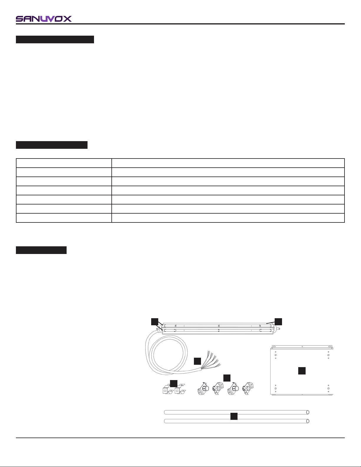
BIO-WALL™
AIR DISINFECTION SYSTEM
Commercial Model
Installation Date: _______________ Installed by: _________________
Installer Contact Info.: _________________________________________
REGISTER
YOUR WARRANTY
ONLINE AT
www.sanuvox.com
IMPORTANT SAFETY INSTRUCTIONS
READ AND SAVE THESE SAFETY INSTRUCTIONS BEFORE USING THIS PRODUCT.
Read and follow all instructions contained in the manual before using the product. Read the maintenance instructions before opening the UV unit
or system. Failure to comply with these instructions may result in injuries or damage to the UV unit or system.
NEVER EXPOSE EYES OR SKIN TO AN OPERATING UV LAMP.
1. Installation and servicing of UV units or systems (in an
air conditioning system or not) can be hazardous. Only
trained and qualied service personnel should install,
repair or service equipment.
2. Untrained personnel can perform basic maintenance
functions such as replacing lamp(s) and/or lter(s). All
other operations should be performed by trained service
personnel.
3. The unit is not to be used by persons (including children)
with reduced physical, sensory or mental capabilities, or
lack of experience and knowledge.
CAUTION: Unit is not a toy. Keep away from
unsupervised children. Do not leave children unattended
with the unit.
4. DO NOT hang onto the UV unit or system.
5. Some UV units or systems could be heavy: Make sure
you have a minimum of 2 people to safely move or install
these UV units or systems, and make sure you adopt the
most ergonomic position possible (use UV unit or system
handles, if applicable).
CAUTION: Installing or maintaining heavy equipment,
especially overhead, can cause back pain or other injuries.
6. When installing or servicing an overhead UV unit or system,
be careful not to fall off the stepladder. Furthermore, make
sure the UV unit or system latches are always in place to
prevent falling parts.
CAUTION: Some parts of some UV units and systems
may open suddenly if the UV unit or system is installed
high up without its locks.
6.1.THIS AIR CLEANER SHALL NOT BE INSTALLED ON THE
HOT-AIR SIDE OF DUCT-TYPE SYSTEMS.
7. Units that are obviously damaged must not be operated.
8. CAUTION: When working on the UV unit or system,
observe precautions on the literature, tags and labels
attached to the UV unit or system, and all other safety
precautions considered as best practices in the HVAC
industry, if applicable.
9. When applicable, local regulation may comprise more
restrictive installation and/or certication requirements.
The aforementioned requirements prevail on those of this
document and the installer agree to conform to these at his
own expense.
10. Follow all the safety instructions outlined in this document
and respect all local and national codes applicable.
11. All UV units or systems contain a UV-C source. Damage to
the housing or unintended use of the UV unit or system may
result in harmful UV-C leaks. UV-C may, even in little doses,
cause harm to the eyes and skin.
12. Never expose eyes or skin to an operating UV lamp.
Therefore, before installing or performing maintenance
on the UV unit or system, TURN OFF AND DISCONNECT
the UV unit or system from all power sources (there
may be more than one switch to disconnect) and also
disconnect the HVAC system, is applicable.
CAUTION: Electrical shock may cause injuries or
possibly death. FIRST AID INSTRUCTIONS: If injured,
consult a doctor.
13. UV rays may damage certain types of lters (polymer or
plastic); please keep the UV unit or system light away from
shining directly on plastic.
14. When installing or performing maintenance on the UV unit
or system, it is recommended to wear safety gloves. In
order to avoid reduced performance of lamp(s), do not
touch lamp glass without gloves.
15. Just like conventional uorescent lamps, UV lamps contain
a small quantity of mercury: if a lamp breaks, clean and
dispose of with care. UV lamps can be disposed/recycled
after use in the same way as any other uorescent lamps.
Contact and follow the specic instructions of your local
and national authorities.
16. Use only specied SANUVOX branded replacement
UV lamps for your UV unit or system. Use of any other
lamps will void your warranty and can result in damage to
the UV unit or system.
17. Sanuvox UV units or systems are not waterproof. DO NOT
INSTALL OUTDOORS OR IN WET LOCATION unless
specied otherwise.
18. The use of a UV unit or system is a supplement to and
not a substitute for standard infection control practices;
users must continue to follow all current infection control
practices, including those related to the cleaning and
disinfection of environmental surfaces.
SAVE THESE INSTRUCTIONS
For any inquiries on a UV unit or system, contact :
Robert Smith
146 Barr St, Saint-Laurent
Quebec, CA, H4T 1Y4
1-888-726-8869

2
Instruction Manual for BIO-WALL™
1-888-726-8869www.sanuvox.com
TABLE OF CONTENTS
IMPORTANT SAFETY INSTRUCTIONS 1
TABLE OF CONTENTS 2
ABOUT THE PRODUCT 3
AVAILABLE MODELS 3
COMPONENTS 3
How it Works 3
ACCESSORIES & KITS 4
SETUP & INSTALLATION 4
What you will need 4
What’s included 4
Setup 4
Step by Step Installation 5
ELECTRICAL DIAGRAM 9
OPERATION 11
How to Operate your Product 11
The 3 Operation Modes 11
Step by Step Change of Operation Mode 12
Remote control (BMS) or limit switch on access door 12
MAINTENANCE 13
How to Replace Lamp(s) 13
Step by Step Lamp Replacement 13
Step by Step Lamp Timer Reset 14
How to Clean your Product 14
STORAGE 14
ULTRAVIOLETS: UVC 14
ELECTRICAL RATINGS, POWER CONSUMPTION & AVAILABLE VOLTAGE 14
RANGE OF ENVIRONMENTAL CONSIDERATIONS 15
TROUBLESHOOTING 15
What you will need 15
Access to LEDs 15
Problems & Solutions Table 15
WARRANTY 16
CUSTOMER SERVICE 16

BA
C
D
E
F
G
3
Instruction Manual for BIO-WALL™
1-888-726-8869www.sanuvox.com
ABOUT THE PRODUCT
Congratulations on the purchase of the Sanuvox BIO-WALL™ UV air disinfection system. Sanuvox systems are the most
advanced air purication systems available, having been proven to deactivate up to 99.9999% of biological and chemical
contaminants that circulate throughout the building or facility. Sanuvox systems have been tested by Medical Universities and
Independent 3rd Party Laboratories.
Engineered and assembled in Montreal (Quebec), Canada, Sanuvox products are carefully crafted to deliver to you the best that
UV air purication can offer, and to improve your air quality.
The BIO-WALL™ offers many advantages such as: single multi-voltage ballast used for all models, BMS control/data and distant
monitoring, ballast box air cooling system and availability of an optinal BioSmart screen to interface with the control circuit.
For information or recommendations on how to size your specic application, please call SANUVOX at 1-888-726-8869.
COMPONENTS
How it Works
The BIO-WALL™ is specically designed to help reduce biological contaminants such as mold, bacteria and viruses that may
be circulated through the HVAC system of the building or facility.
The BIO-WALL™ is installed in the RETURN (preferred) or SUPPLY plenum of the HVAC system purifying the air passing
through the air duct. The actual percentage of destruction obtained is based on the duct size, percentage of fresh air, velocity,
the number of passes and specic contaminants to be treated. Depending on these variables, more than one BIO-WALL™ may
be required.
A. UV Lamp
B. Anodized Aluminum Parabolic Reector
C. Clamp Assemblies (2)
D. 3/4" Support Rod
E. Mounting Flanges (2)
F. Teon Wire Set (20 feet)
G. Ballast Box
AVAILABLE MODELS
Models Description
BIOM18G 18" High Intensity 5 UV Lamps Disinfection System
BIOM24G 24" High Intensity 5 UV Lamps Disinfection System
BIOM30G 30" High Intensity 5 UV Lamps Disinfection System
BIOM40G 40" High Intensity 5 UV Lamps Disinfection System
BIOM50G 50" High Intensity 5 UV Lamps Disinfection System
BIOM60G 60" High Intensity 5 UV Lamps Disinfection System

4
Instruction Manual for BIO-WALL™
1-888-726-8869www.sanuvox.com
ACCESSORIES & KITS
The following optional accessories and/or kits work great with your product (sold separately).
BioSmart Screen
BIOSCREEN
7" touch screen informing the user in real time.
Sold with a 20' Ethernet cable and a grommet.
Interlok Switch
MSCSWC14
The interlok switch will shut down the BIO-WALL™
operation should the access door be opened.
For instruction manuals or information about your optional accessories and/or kits, please call SANUVOX at 1-888-726-8869
or visit www.sanuvox.com.
SETUP & INSTALLATION
What you will need
A knife to unpack all the components, a drill with 1/8 and 1/2 bits, an iron saw, a Phillips #2 screwdriver, a nutdriver key with 11/32
and 1/4 sockets.
CAUTION: Handle your product with
care to avoid breaking parts. Make sure
you have a free and safe space to unpack,
install and setup your product. Conrm
you have access to the necessary power
source for the product requirements
(see unit or system label). If you have
any questions regarding the installation
instructions, call SANUVOX at 1-888-726-
8869.
What’s included
The BIO-WALL™ (lamp reector assembly
with 10' cable), a ballast box, mounting clips
(2), support anges (4), support rods (2) and
a basic installation kit.
The installation kit includes: a UV caution
decal, a maintenance decal, a wiring
diagram and a snap bushing.
Setup
While selecting the appropriate location for your BIO-WALL™, refer to your customized sizing and placement proposal. If you do
not have the customized proposal, call SANUVOX at 1-888-726-8869 to obtain one at no-charge.
The ballast boxes are to be installed on the outside of the air central in a dry area.
CAUTION: Make sure the site can be supplied with the necessary power requirements. Ensure that there is adequate clearance
for service and maintenance.

5
Instruction Manual for BIO-WALL™
1-888-726-8869www.sanuvox.com
Step by Step Installation
STEP 1
STEP 2
STEP 3
STEP 4
1. Select where the BIO-WALL™ extrusion will be installed. The
location requires a straight duct of a minimum length without obstruction.
Refer to the table below according to the length of the BIO-WALL™ to be
installed.
Model Length required
for installation
Distance between
support rods
BIOM18 28" (71 cm) 25.25" (64 cm)
BIOM24 34" (86 cm) 31.25" (80 cm)
BIOM30 40" (102 cm) 37.25" (94.5 cm)
BIOM40 50" (127 cm) 47.25" (120 cm)
BIOM50 60" (152 cm) 57.25" (145.5 cm)
BIOM60 70" (178 cm) 67.25" (171 cm)
NOTE: The BIO-WALL™ can be installed in the return plenum or in the
supply duct indistinctly. In any case, the extrusion must be positioned
parallel to the airow and in the center of the ventilation duct.
2. Select the location where the ballast box will be installed. Often the
ballast box is installed on the conduit or on one of the sides. You can
install it on a nearby wall, but make sure of the distance: you only have 3
m of cable between the box and the extrusion.
NOTE: Operating information can be provided in 2 ways: via dry contacts
that relay data to a BMS or via a BioSmart touch screen (optional) that
can be installed up to 100 feet (32m) away.
3. Install an access door on the section that will receive the BIO-
WALL™ extrusion. The size of the access door will be determined by
the height of the duct.
NOTE: The access door must be able to uncover the upstream section of
the BIO-WALL™, so that the lamp connectors are directly in front of the
opening. So that when it comes time to change the lamps, this operation
can be done easily.
4. Install a limit switch on the access door. This will automatically cut off
the power supply to the system if someone inadvertently opens the door.
In this way, anyone is protected from being exposed to UV rays.
NOTE: The switch must be approved in the country where the installation
is made and must have the following characteristics: insulation of 600
volts and 500,000 cycles of operation.
In Canada and the USA, the MSCSWC14 switch is available from SANUVOX.
Examples of access doors

6
Instruction Manual for BIO-WALL™
1-888-726-8869www.sanuvox.com
STEP 5
STEP 11
STEP 6
STEP 7
STEP 8 & 9
STEP 10
Assemble BIO-WALL™ Supports
5. Start by measuring the height of the duct. Then cut two pieces of support
pipe this height – minus 1.5" (3.8 cm) to accommodate the mounting
anges.
11. Having determined where the ballast box will be installed, drill a 1.125”
(2.85 cm) hole in the conduit to bring the cable through.
NOTE: Put the supplied plastic grommet in the hole to protect the cable.
6. Insert a clamp assembly on each section and tighten it in the center with
the bolts provided for this purpose.
7. Attach the mounting anges to each end of the pipes and tighten them in
place.
Install 2 Assembled Supports in Duct
8. Knowing the total length of your installation (see the table in step 1),
attach the pipe furthest downstream, in the center of the conduit. Screw
it in place, making sure that the clamp is in the center of the pipe, facing
you and its opening facing up.
9. Attach the 2nd pipe, the one closest to your access door, by distancing it
from the other according to the table in step 1. Screw it in place, making
sure that the xing clamp is in the center of the hose, pointing towards
you and its opening facing upwards.
Install Extrusion and Lamps onto Clamps
10. Without removing the lm that protects the lamps, take the extrusion by
the side of the power cable and insert everything into the duct: place the
extrusion at the bottom of the duct.

7
Instruction Manual for BIO-WALL™
1-888-726-8869www.sanuvox.com
STEP 12
STEP 13
STEP 14
STEP 15
12. Slip the end of the cable through the hole and gently pull the cable out
of the conduit.
NOTE: At some point, you will be in a position to lift the extrusion and
gently slide it into the mounting clips. Be sure to leave some slack in the
cable inside the conduit.
You can now tighten the nuts that hold the extrusion into the clamps.
Install Ballast Box on Slected Surface
13. Remove the case cover by turning the 4 screws to the left. Lay it aside.
14. Fix the box to the surface using the 6 self-tapping screws provided. The
box can be installed vertically or horizontally. Make sure the box is within
reach of the wire for the connection.
Connect Cable to Ballast Box
15. Remove the ring from the connector and pass the end of the cable
through the opening provided in the box, between the two fans. Secure it
in place by putting the ring back in place. The rest of the cable should be
secured in place with clamps (not supplied).
STEP 16 16.The section of the cable in the box is made up of 20 wires, ie 5 wires of
4 strands – 2 red and 2 blue. Just nearby is a terminal block to which the
5 ballasts are connected, the rst being at the very bottom.
Select the wire identied #1, separate the red and blue strands and plug
them separately into the section of the terminal block relating to ballast
#1. Be sure to plug the red wires into the sections adjoining the red wires
and the blue ones the same, adjoining the blue wires.
NOTE: To simplify your task, you can use a mini at-blade screwdriver: if
you push it into the square opening at the side of the wire, the insertion
or removal of the wire will be easier. If you remove the blade, the wire will
get stuck.

8
Instruction Manual for BIO-WALL™
1-888-726-8869www.sanuvox.com
STEP 17
STEP 18
STEP 19
17. Pull on each wire to ensure a rm connection, then repeat steps 15-16-
17 for the next 4 segments.
Connect Limit Switch to 5 VDC Circuit
18. Referring to the electrical diagram, identify the SW and 5 VDC terminals
on the electronic board terminal block.
Insert two control wires into it and connect them to the limit switch. In this
way, if the switch is activated, the electronic circuit will cut off the power
supply.
NOTE: Remember to put the YELLOW WARNING stickers on the access door.
Interconnection to Building Management System (BMS) or
BioSmart Touch Screen (optional)
NOTE: The addition of control wires or a touch screen is not necessary
for the operation of the BIO-WALL™.
19.If you have purchased a BioSmart touch screen, now is the time to
connect it to your ballast box. Follow the instructions provided with the
screen.
NOTE: Each BioSmart display has been congured for a specic BIO-
WALL™. Be sure to identify the correct one.
Furthermore, if you wish to share the information with a management
controller, SANUVOX offers 3 BMS operating modes: an external 24
VDC power supply will be required. Please refer to the “OPERATION”
section.
STEP 20 Certied Electrician Required to Power Ballast Box
20. The power supply can be 120V or 240V (optional), to a circuit breaker
with a minimum of 10A. You only have to connect the black and white
wires as well as the ground.
NOTE: In certain circumstances, a manual circuit breaker can also be
installed near the ballast box.
Once the power is supplied, replace the cover and secure it in place by
turning the 4 screws to the right.
You are now ready to enjoy
superior indoor air quality and safety.

ELECTRICAL DIAGRAM


11
Instruction Manual for BIO-WALL™
1-888-726-8869www.sanuvox.com
OPERATION
How to Operate your Product
The BIO-WALL™ integrates dry contacts to communicate with a building management PLC. However, you must choose between
3 operating modes.
CAUTION: The recommended operating temperature is between 4 to 66°C (40 to 150°F). Using the BIO-WALL™ outside
of this temperature range may reduce its performance. For optimum performance, the air temperature in the duct should be
between 15 to 20°C (60 to 70°F).
The 3 Operation Modes
Note that by default following installation, the BIO-WALL™ starts in Mode 2.
MODE 1
BIO-WALL™ will start automatically when set to Mode 1.
The signals from L1 to L5 indicate for each of the lamps from 1 to 5 if they are functional.
If the lamp is working, the signal read will be VCC.
The installer/user must supply 0V and VDC (5V to 24V) to the PCB.
NOTE: For the BIO-WALL™ to work in Mode 1, it is necessary that 7 wires are connected between the electronic card and the BMS.
MODE 2
BIO-WALL™ will start automatically when set to Mode 2.
VCC signal from L1 will indicate that all lamps are working.
If the output from L1 is 0V, it means that one or more lamps are not working.
The installer/user must supply 0V and VDC (5V to 24V) to the PCB.
NOTE: For the BIO-WALL™ to work in Mode 2, it is necessary that 3 wires are connected between the electronic card and the BMS.
MODE 3
The installer/user must supply 0V and VDC (5V to 24V) to the PCB.
If the wire-jumper is in BP position, BIO-WALL™ will start automatically.
Otherwise, BIO-WALL™ will start only if activated through the PLC signal provided to the PCB from the user BMS. VCC signal
from the PLC will turn ON the BIO-WALL™, and a 0V signal will turn it OFF.
NOTE: For the BIO-WALL™ to work in Mode 3, it is necessary that 8 wires are connected between the electronic card and the BMS.
Mode 3 PCB Signals
L1 = Door Closed (VCC) or Door Open (0V)
L2 = Lamps working (VCC) or One or more lamp is not working (0V)
L3 = Fan 1 working (VCC) or Not working (0V)
L4 = Fan 2 working (VCC) or Not working (0V)
L5 = All lamps have less than 17000 hrs (VCC) or One or more lamps have exceeded their lifespan (0V)
Refer to the pull-out diagram on the
previous page for more information.

12
Instruction Manual for BIO-WALL™
1-888-726-8869www.sanuvox.com
FIG. 2
FIG. 3
FIG. 1
Step by Step Change of Operation Mode
By default
1. Turn off the power at the ballast box.
2. Remove the cover by turning the 4 screws to the left.
3. Locate the section in Figure 1.
4. Turn power back on: all LEDs will ash for 5 seconds.
Then, a specic sequence will be displayed in RED and GREEN for 5
seconds to indicate the selected operation mode:
Mode 1 GRRRR
Mode 2 R G R R R
Mode 3 R R G R R
The second LED will be GREEN (see Figure 2) to indicate that the BIO-
WALL™ is in Mode 2, which is the default mode.
5. After this last 5 seconds, all LEDs will turn GREEN (see Figure 3) to
indicate that the mode is saved.
To change the mode
1. Repeat steps 1-4 above.
2. While the mode sequence is displayed (you have 5 seconds), press the
button: each time, you will change modes.
3. When you have selected the desired mode, wait 5 seconds for it to be
saved.
Remote control (BMS) or limit switch on access door
A wire jumper is factory-installed on the PLC and PLC24 terminals: this conguration automatically turns on the lamps when
the box is powered.
If you want to turn on the lamps remotely, remove the wire jumper and connect a pair of wires to these contacts: sending a 5V
- 24 VDC signal will turn on the lamps and its interruption (0V) will turn them off.
You can also, for added security, connect these wires to a limit switch on the access door, which will only require a 5V supply.
CAUTION: In Mode 3, if you wish to light the lamps with the BMS, you must move the jumper to the right (see Figure 1 of
‘Step by Step Change of Operation Mode’) and connect your wires to the PLC contact and 0V.
Button
Wire-jumper

13
Instruction Manual for BIO-WALL™
1-888-726-8869www.sanuvox.com
MAINTENANCE
How to Replace Lamp(s)
Lamps should be replaced every 2 years to maintain design specications.
Replacing the lamps of a BIO-WALL™ is quick and easy. Turn off the power source. Remove and dispose of old lamps as you
would regular uorescents. Replace new SANUVOX brand UV lamps. Turn the power source back on.
See below for detailed step-by-step instructions.
CAUTION: In order to avoid reduced performance of lamp(s), do not touch lamp glass without gloves.
STEP 2
STEP 3
STEP 4
STEP 5
1. Before doing any maintenance, be sure to turn off the power.
2. Open the duct access door.
3. Carefully pull one of the lamps to remove it from the metal clips holding
it in place. Gently remove the connector from the end of the lamp and
pull the lamp out of the conduit.
NOTE: If the connector is damaged, do not hesitate to replace it.
4. Take a new lamp – with your gloved hands, insert it into the conduit and
plug the connector into it. If you have difculty inserting the connector,
turn it 90°.
5. Insert the lamp into the extrusion on the metal clamps and gently secure
it in place. It is likely that you will have to tighten the clamps a little
before putting the lamp in.
STEP 6
STEP 8
6. Do the same for the other 4 lamps.
7. When you are nished, close the access door and turn the power back on.
8. All that remains is to reset the hour counter to 17,000 hours.
Step by Step Lamp Replacement

14
Instruction Manual for BIO-WALL™
1-888-726-8869www.sanuvox.com
How to Clean your Product
For optimum performance, lamps should be protected from dust and residue. Since the lamps are installed in the direction of
the air ow, it is unlikely that they will accumulate dust. Nevertheless we suggest to check their fouling if possible after 6 months.
Clean the lamps and their reectors as needed with mild soap or isopropyl alcohol. Use a rag. Always test the cleaner to make
sure it does not damage the surface.
CAUTION: Under no circumstance should water be sprayed or splashed onto the product.
STORAGE
The BIO-WALL™ does not require specic storage. It is a permanent unit that works continuously when powered.
CAUTION: Keep away from unsupervised children. This unit is not a toy.
ULTRAVIOLETS: UVC
The UVC (254 nm) wavelengths produced by Sanuvox UV units and systems are the same as the ultraviolets produced by the
Sun. The UVC attacks the micro-organisms on a molecular level deactivating the contaminants. Unlike conventional UV lamps
on the market, Sanuvox UV units and systems use a patented process designed to deliver the maximum UV dosage to the
moving airstream or surface.
CAUTION: Never expose eyes or skin to an operating UV lamp.
ELECTRICAL RATINGS, POWER CONSUMPTION & AVAILABLE VOLTAGE
The BIO-WALL™ in its largest conguration has a power consumption of up to 775 W each.
The BIO-WALL™ necessary power requirements is 115-277 VAC, 50/60Hz.
The BIO-WALL™ requires a dedicated circuit breaker with a minimum rating of 10A.
The door switch must operate on 5 VDC.
See product label to conrm power consumption of your specic unit or system.
NOTE: IF YOU EXPERIENCE A PROBLEM, PLEASE CONTACT CUSTOMER SERVICE FIRST OR SEE YOUR WARRANTY.
DO NOT RETURN THE PRODUCT TO THE ORIGINAL PLACE OF PURCHASE. DO NOT ATTEMPT TO OPEN THE
PRODUCT OR TAMPER WITH ITS COMPONENTS WITHOUT CONTACTING CUSTOMER SERVICE FIRST. DOING SO
MAY VOID YOUR WARRANTY AND CAUSE PERSONAL INJURY OR DAMAGE TO THE PRODUCT.
Step by Step Lamp Timer Reset
STEP 1
1. Press and hold the Mode button until the LEDs ash RED, then turn
GREEN.
2. The countdown of all lamps is reset to 17000 hrs.

15
Instruction Manual for BIO-WALL™
1-888-726-8869www.sanuvox.com
RANGE OF ENVIRONMENTAL CONSIDERATIONS
1) Indoor or outdoor use Indoor*
2) Altitude < 2,000m
3) Temperature 5 to 65°C (41 to 149°F)
4) Relative humidity Non condensing 70%
5) Mains supply voltage uctuations 10%
6) Overvoltage category II
7) Wet location IPX0
8) Pollution degree 2
* If installed outside, ballast box must absolutely be installed in a waterproof enclosure provided with suffcient air circulation to
maintain the temperature in the permissible range.
Problem Possible Cause Solution
All LEDs are RED. - In MODE 3, the PLC works.
- The ventilation duct access door is open. - Make sure to close the access door properly.
- Both fans are stopped. - The system must have at least one fan in
operation for the lamps to work: replace the fans.
- All lamps and ballasts are faulty. - Replace the UV lamps.
- Replace the ballasts.
One (1) of the LEDs is RED. - The lamp or ballast associated with this LED is
faulty.
- Replace the UV lamps.
- Replace the ballasts.
The LEDs ash from RED to GREEN. - The lamps have passed their 2 years of life. - Replace the UV lamps.
The LEDs in the ballast box are off. - The system is not powered or the power supply is
faulty.
- Make sure the system is powered on.
- Replace the power supply.
Contact your contractor for all your needs in terms of replacement parts:
UV Lamps, Fan, Clamp Assembly, Ballasts, etc.
TROUBLESHOOTING
If your product is not working properly, refer to the following.
What you will need
A Phillips No. 2 screwdriver, a non-magnetic 7/16" nutdriver and spare parts.
Access to LEDs
When the BIO-WALL™ is not used with the BMS hookup or BioSmart display (optional), your only way to determine if the lamps
or fans are working is by looking at the LEDs inside the BIO-WALL™ ballast box.
When opening the cover, be sure to proceed with care since the PCB module has components that are powered by high voltage.

16
Instruction Manual for BIO-WALL™
1-888-726-8869www.sanuvox.com
CUSTOMER SERVICE
TO ORDER REPLACEMENT PARTS
PLEASE CONTACT YOUR CONTRACTOR OR SANUVOX CUSTOMER SERVICE
Toll-Free Phone #: 1-888-726-8869
Email: [email protected]
Website: www.sanuvox.com
Please be sure to specify product name.
Replacement parts for this product
BST120/277SHS Ballast with input of 115-277 VAC, 50/60Hz
LMPHGS180 18" T6 High Intensity Germicidal Lamp for BIOM18G
LMPHGS240 24" T6 High Intensity Germicidal Lamp for BIOM24G
LMPHGS300 30" T6 High Intensity Germicidal Lamp for BIOM30G
LMPHGS400 40" T6 High Intensity Germicidal Lamp for BIOM40G
LMPHGS500 50" T6 High Intensity Germicidal Lamp for BIOM50G
LMPHGS600 60" T6 High Intensity Germicidal Lamp for BIOM60G
FLGFIXTUB Mounting anges (2)
CON-TUB-19 Clamp assembly (2)
FSTCLP5 Stainless steel spring clamp
TUBAA66 3/4" support rod
BIOSCREEN BioSmart touch screen for BIO-WALL™
CON-LMP-41 Gaynor Plug
WARNING: Use only specied SANUVOX branded replacement UV lamps with your unit or system. Use of any other
lamps will void your warranty and can result in damage to the unit, system and/or lamp(s).
WARRANTY
You should rst read all instructions before attempting to use this product.
For this warranty to be valid, keep a copy of the proof of purchase.
UV lamp 2 years
Ballast 15 years
Electronic Components 1 year
A. This limited warranty applies to repair or replacement of product found to be defective in material or workmanship. This warranty does not apply to
damage resulting from abusive, unreasonable use or supplemental damage. Defects that are the result of normal wear and tear will not be considered
manufacturing defects under this warranty.
SANUVOX IS NOT LIABLE FOR INCIDENTAL OR CONSEQUENTIAL DAMAGES OF ANY NATURE, ANY IMPLIED WARRANTY OF MERCHANTABILITY
OR FITNESS FOR A PARTICULAR PURPOSE ON THIS PRODUCT IS LIMITED IN DURATION TO THE DURATION OF THIS WARRANTY.
Some jurisdictions do not allow the exclusion or limitation of incidential or consequential damages or limitation on how long an implied warranty last, so
the above limitations or exclusions may not apply to you. This warranty gives specic legal rights, and you also may have other rights which vary from
jurisdiction to jurisdiction. This warranty applies only to the original purchaser of this product from the original date of purchase.
B. At its option, SANUVOX will repair or replace this product if it is found to be defective in material or workmanship.
C. This warranty does not cover damage resulting from any unauthorized attempts to repair or from any use not in accordance with the instruction manual.
D. This warranty does not cover the lters, pre-lters or other accessories (if included), except for material or workmanship defects.
Call us toll-free at 1-888-726-8869 or email: [email protected]
Please be sure to specify product name.
NOTE: IF YOU EXPERIENCE A PROBLEM, PLEASE CONTACT CUSTOMER SERVICE FIRST OR SEE YOUR WARRANTY. DO NOT RETURN THE PRODUCT
TO THE ORIGINAL PLACE OF PURCHASE. DO NOT ATTEMPT TO OPEN THE PRODUCT OR TAMPER WITH ITS COMPONENTS WITHOUT CONTACTING
CUSTOMER SERVICE FIRST. DOING SO MAY VOID YOUR WARRANTY AND CAUSE PERSONAL INJURY OR DAMAGE TO THE PRODUCT.
REGISTER
YOUR WARRANTY
ONLINE AT
www.sanuvox.com
Other manuals for Bio-Wall MAX
2
Table of contents
Other Sanuvox Laboratory Equipment manuals

Sanuvox
Sanuvox ASEPT.2X User manual

Sanuvox
Sanuvox S300 MED2 Operator's manual

Sanuvox
Sanuvox S300 VOC User manual

Sanuvox
Sanuvox S300 VOC User manual

Sanuvox
Sanuvox Bio-Wall MAX User manual

Sanuvox
Sanuvox ASEPT.2X User manual

Sanuvox
Sanuvox SABER MAGNET User manual

Sanuvox
Sanuvox ASEPT.2X User manual

Sanuvox
Sanuvox SANUVAIR S1000 OZD User manual

Sanuvox
Sanuvox S300 User manual