Sanwa PC700 User manual

PC700
DIGITAL MULTIMETER
INSTRUCTION MANUAL

Table of Contents
[1] SAFETY PRECAUTIONS
1-1 Explanation of Warning Symbols
1-2 Warning Instructions for Safe Use
1-3 Overload Protection
[2] APPLICATIONS AND FEATURES
2-1 Applications
2-2 Features
[3] Parts Identification
3-1 Multimeter and Test Leads
3-2 Display
[4] DESCRIPTION OF FUNCTIONS
4-1 Power Switch/Function Selector
4-2 Auto Power Saving
4-3 Low Battery Indication
4-4 Measuring Function Selection
4-5 Range Hold
4-6 Data Hold
4-7 Beeper Control
4-8 PC (Personal Computer) Interface
4-9 Test Leads Improper Connection Warning
4-10 Relative Measurement
4-11 Terms
[5] Measuring procedures
5-1 Pre-operational Check
5-2 AC Voltage ( ) / Frequency (Hz) Measurement
5-3 DC/AC Voltage (V) Measurement
5-4 DC/AC Voltage(mV),Logic-Level Frequency ( Hz)and
DutyCycle( D%) Measurement
5-5 AC Voltage( m ) / Frequency (Hz) Measurement
5-6 Resistance (Ω) Measurement
5-7 Continuity Check ( )
5-8 Capacitance( )Measurement,Diode( )Test
5-9 DC/AC Current (A), AC Current (m ,µ, )/ Frequency
(Hz) Measurement
5-10 MeasurementswithSeparatelyAvailableAccessories
[6] MAINTENANCE
6-1 Simple Examination
6-2 Calibration
6-3 Battery and Fuse Replacement
6-4 Storage
[7] AFTER-SALE SERVICE
7-1 Warranty and Provision
7-2 Repair
7-3 SANWA web site
[8] SPECIFICATIONS
8-1 General Specifications
8-2 Measuring Range and Accuracy
1
2
3
4
4
5
7
8
8
9
9
10
10
10
11
12
12
12
14
16
19
21
24
26
28
30
34
40
44
44
45
46
47
47
48
49
51

―2 ―― 1 ―
1-2 Warning Instructions for Safe Use
1. Do not use the instrument if the meter or test leads look
damaged.
2. Be sure to use the specified fuse.
Neither use unspecified fuse nor short-circuit the fuse holder.
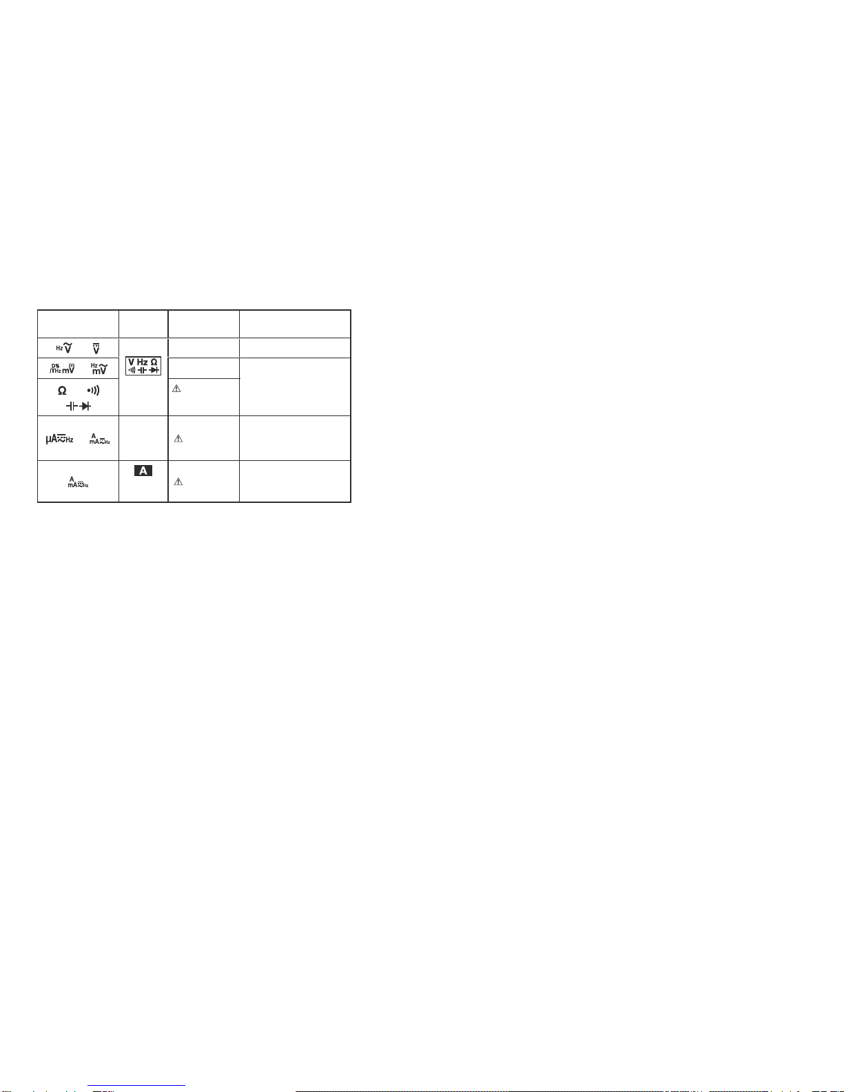
3. Do not apply higher voltage or current than the max. ratings
by each function. (See 1-3)
4. Use caution when working with voltages above 33 V ac rms,
46.7 V ac peak, or 70 V dc. These voltages pose a shock
hazard.
5. Do not use the meter to measure lines that may have
inductive voltage or surge voltage (e.g. motors) because the
input voltage may exceed the maximum rated voltage.
6. Never operate the meter with the case or battery lid removed.
7. Remove test leads from the meter before opening the meter
case for replacing the battery or fuse.
8. Never attempt to repair or modify the instrument, except for
battery and fuse replacement.
9. Do not use any unspecified type of test leads.
10.Keep your fingers behind the finger guards of the test leads
while measurement.
11.Connect the common test lead (Black) before you connect
the live test lead (Red). Disconnect the live test lead first.
12.Make sure the function, range, and terminals are properly set.
13.Do not switch the function, range, or the plugs to another
while measurement.
14.Do not operate the meter when it is wet or with wet hands.
WARNING
Incorrect measurement may be performed in a ferromagnetic or
intense electric field near transformers, high-current circuits, and
radio equipments.
CAUTION
[1] SAFETY PRECAUTIONS
*Before use, read the following safety precautions.
This instruction manual explains how to use your digital multimeter
PC700. Before using, read through this manual to reduce the risk
of fire , electric shock, and/or injury. And save it together with the
product so that you can refer to the manual as necessary.
Use the instrument only as specified in this manual or the protection
provided by the instrument may be impaired.
The instructions given under the headings of " WARNING" and
must be followed to prevent accidental burn andelectric shock.
1-1 Explanation of Warning Symbols
The meanings of the symbols used in this manual and attached to
the product are as follows.
:Extremely-important instructions for safe use
・WARNING identifies conditions and actions that could result in
accidental burn and electric shock.
・CAUTION identifies conditions and actions that could cause
damage the instrument.
:Do not touch! Possible high voltage.
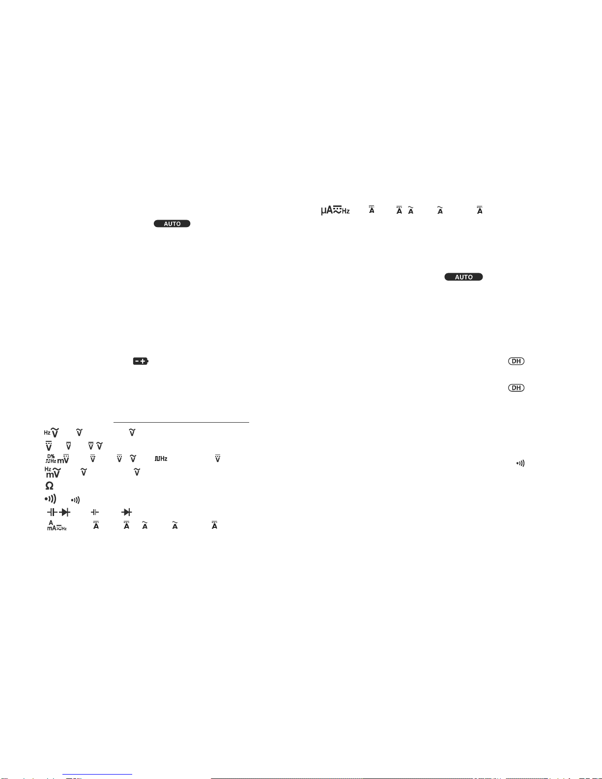
:Ground :Diode Hz:Frequency
:Fuse :Beep :Logic-LevelFrequency
:DirectCurrent(DC) :Capacitor :Duty Cycle
:Alternate Current (AC) :Resistance
:Double Insulation or Reinforced

―4 ―― 3 ―
1-3 Overload Protection
Function
Measuring
terminal
Max.RatedInput Overload Protection
「 」,「 」
and
COM
1000V dc/ac 1050V rms, 1450V peak
「 」,「 」
10V dc/ac
600Vrms
「 」,「 」
「 」
Do not apply
any voltage or
current.
「 」,「 」
mAµA
and
COM
600mA dc/ac
Do notapply
anyvoltage. 0.63A/500V Fuse
Breaking capacity: 50kA
「 」 and
COM
10A dc/ac
Do notapply
anyvoltage. 12.5A/500V Fuse
Breaking capacity: 20kA
[2]APPLICATIONS AND FEATURES
2-1 Applications
This instrument is a portable digital multimeter designed to
measure light electric circuits. The instrument offers not only
measurements for small communication equipments, home
electric appliances, output from a wall socket, and many batteries,
also circuit analyses with additional functions.
2-2 Features
• Compliant with IEC61010-1 CAT. Ⅲ600V, CAT. Ⅱ1000V, and safe
design using fuseswith large number of breaking capacity.
• 9999 count display (ACV, DCV, Hz)
• Fast response display
(Numeric parts: 5 times/Sec. Bar graph part: 60 times/Sec.)
• Dual Display shows "Voltage or Current and its Frequency", and
"AC components and DC components of Voltage or Current"
• Maximum DC/AC voltage measurement resolution: 0.01 mV
• Frequency (Sensitivity selectable),
Wide capacitance range (0.01nF to 25.00mF)
• Relative mode with auto ranging
• PCLink7 (separately available software) allows you to download
logged data into your PC with USB optical communication unit
(KB-USB7)

LCD display
Range hold button
Select button
Relative button
Data hold button
Power/
Function selector
Measuring terminal
for A
Measuring terminal
for mAµA
Common terminal Measuring
terminal
Light shielding magnet cap
Optical
communication
unit connector
StandBattery door
Holster
Finger guards
Plugs Test probe (red)
Test probe (black)
Test leads TL-23a
3
Detachable test pin covers
Test pins
⇒
↑
↓
Light shielding magnet cap
Magneticallyattractable
materialwall(e.g.steel)
DMM body Attach the light shielding magnet cap
with side touched to the wall.
―6 ―― 5 ―
[3] Parts Identification
3-1 Multimeter and Test Leads
With the detachable test pin covers: CAT. III 600V
Without the detachable test pin covers: CAT. II 1000V
How to detach the light shielding magnet cap
Turn the light shielding magnet cap counterclockwise to detach.
An application of the light shielding magnet cap
Note:
Keep the light shielding magnet cap away from cellular phones,
analog watches, floppy disks, magnetic cards, magnetic tapes, and
magnetic tickets. Otherwise, the memorized information may be lost.

①
②
③
④
⑤ ⑥
⑦
⑧
⑨
⑩⑪
⑫
⑬
⑦ ⑧
①Main display
②Sub display
③Analog bar graph
④Relative mode indicator
⑤Auto range mode indicator
⑥Data hold indicator
⑦DC measurement indicator
⑧AC measurement indicator
⑨Polar charactor
⑩Continuity check indicator
⑪Low battery voltage indicator
⑫Unit of readings for main display
⑬Unit of readings for sub display
―8 ―― 7 ―
3-2 Display
[4] DESCRIPTION OF FUNCTIONS
4-1 Power Switch/Function Selector
Turn the switch to turn on/off the power and select a measuring
function. All segments of the LCD display will be turned on for 1
seconds after power-on, and then the meter will be ready to use.
Note:
The push buttons between the display and the function selector
work differently depending on how long you press. In this
manual, "press" means pressing momentary and "press and
hold for 1 sec. or more"means pressing longer.
4-2 Auto Power Saving
The Auto Power Saving mode turns the meter off automatically
after approximately 30 minutes of no activities. While the Auto
Power Saving mode, following activities set the auto power saving
back.
1) Function selector or push button operations
2)Non-OL readings in the Ωfunction, diode test, or continuity
check, non-zero readings in the Duty cycle/Frequency
measurement functions, or significant measuring readings of
above 512 counts in the other function ranges
While data communication to your PC is in use, Auto Power
Saving mode will be temporarily cancelled.
4-2-1 How to get back from theAuto Power Saving
Press the SELECT, RANGE HOLD, △REL、or HOLD button, or
disconnect theobject to measure and turn the power switch off and then
back on, and select a function before connecting the object.

―10 ―― 9 ―
4-2-2 How to disable the Auto Power Saving
Press the SELECT button while turning the meter power on.
Release the SELECT button after is turned off. (All
segments of the display turn on after power-on.) Then the meter
will be ready to use.
Turn the power switch OFF and then back on to resume.
Note:
Even in the Auto Power Saving mode, approx. 50µA will be
consumed. When in the auto power saving mode, intense
light like the direct sunlight into the optical communication unit
on the back of the DMM increases the consumption current.
Mount the attached light shielding magnet cap on the optical
comminucation unit connector when not in use. Always turn the
power switch to the OFF position when the meter is not in use
for a long time.
4-3 Low Battery Indication
Decreasing the internal battery voltage to approx. 7V due to
wearing down turns on the indicator on the LCD display.
Replace the battery with new one when the indicator turns on.
Use under "Low Battery" may cause malfunctions.
4-4 Measuring Function Selection
At each position of the function selector, press SELECT button
(⇒) to select measuring functions as follows.
* Dual display: [Main display/Sub display]
・
「 」
:[ /Hz ] ⇔[ Hz/ ]
・
「
」
:[ ] ⇔[ / ]
・
「 」
:[m ] ⇒[m /m ] ⇒[ ] ⇒[D%] ⇒[m ] ⇒…
・
「」
:[ m /Hz] ⇔[ Hz/ m ]
・
「 」
:[Ω](SELECT button will not be used here.)
・
「 」
:[ ](SELECT button will not be used here.)
・
「 」
:[ ] ⇔[ ]
・
「
」
:[(m) ]⇒[(m) /(m) ] ⇒[(m) /Hz] ⇒[ (m) ] ⇒…
・
「 」
:[µ]⇒[µ/µ]⇒[µ/Hz ] ⇒[µ]⇒…
Note:
The last selection of each function will be saved as power up
default for repeat measurement convenience.
4-5 Range Hold
Press the RANGE HOLD button to select manual-ranging, and the
meter will remain in the range it was in. ( turns off.) In
the manual-ranging mode, press the button again to step through
the ranges. Select an appropriate range making sure units and
decimal point positions. To resume auto-ranging mode, press and
hold the button for 1 second or more.
Note:
Manual ranging mode is not available in the Hz functions.
4-6 Data Hold
Press HOLD button to freeze present reading for later view. (
indicator turns on.) Input fluctuation will not reflect on the indicated
value. Press the HOLD button again to disable the data hold
feature and go back to the normal measurement mode. (
indicator turns off.)
Note:
Function changes or functional operations will cancel the data hold
feature.
4-7 Beeper Control
Press the RANGE HOLD button while turning the meter power on
to disable the beeper. Release the RANGE HOLD button after
is turned off. (All segments of the display turn on right after power-
on.) Then the meter will be ready to use. Turn the power switch
OFF and then back on to resume.
Note:
The beeper for the continuity check and the plug improper
connection warning will not be disabled.

―12 ―― 11 ―
4-9 Test Leads Improper Connection Warning
The meter beeps as well as displays “InEr” to warn the user
against possible damage to the meter due to test leads improper
connections to the , or input jacks when other function
(like voltage function) is selected. (Temperature measurement
function is an exception.)
Note:
“InEr” warning may be indicated due to weak battery even if the
test leads are connected properly.
4-10 Relative Measurement
Press the △REL button to activate the relative measurement
mode and △indicator turns on. The relative measurement
mode offsets the meter to display relative values against
a reference. The meter displays its readings subtracting
the reading at the moment the △REL button is pressed.
Press △REL button again to exit the relative measurement
mode. This function works only on the main display.
4-11 Terms
Analog bar graph
The analog bar graph provides a visual indication of
measurement like a traditional analog meter needle.
Average sensing RMS calibrated
RMS (Root-Mean-Square) is the term used to describe the
effective or equivalent DC value of an AC signal. Most digital
multimeters use average sensing RMS calibrated technique to
measure RMS values of AC signals. This technique is to obtain
the average value by rectifying and filtering the AC signal.
The average value is then scaled upward (calibrated) to read
the RMS value of a sine wave. In measuring pure sinusoidal
waveform, this technique is fast, accurate and cost effective.
In measuring non-sinusoidal waveforms, however, significant
errors can be introduced because of different scaling factors
relating average to RMS values.
⇒
USB Optical Communication Unit
(KB-USB7)
Optical Communication Unit Connection
4-8 PC (Personal Computer) Interface
The instrument equips with an optical isolated interface port at the
meter back for data communication. KB-USB7, dedicated USB
optical communication unit (separately available), and PCLink7,
dedicated software, allow you to transfer real time readings and
internally logged data to your PC. For more information, see the
"HELP" for PCLink7 (PC linkage software).
Note:
Intense light like the direct sunlight into the optical communication
unit on the back of the DMM increases the consumption current.
Mount the attached light shielding magnet cap on the optical
comminucation unit connector when not in use.

―14 ―― 13 ―
[5] Measuring procedures
5-1 Pre-operational Check
1. Do not use the instrument if the meter or test leads look
damaged.
2. Make sure the test leads and the fuse are not broken.
WARNING
Make sure the low battery indicator is off after power-on. Replace
the battery with new one if the indicator is on.
CAUTION
Perform pre-oparational check for safety.
(Inspection using continuity check)
Contact us for repair.
START
Meter/Test leads damaged?
①Connect the red plug of the test lead to measuring
terminal and the black one to the COM terminal.
②Set the function selector to .
③Short-circuit between the red and black test pins.
Ωturns on?
Beeper sounds?
Finished
Does not turn on.
Does not sound.
Turns on. Sounds
Looks OK
Damaged
*In the case nothing is displayed, check for the battery.

/ Hz Hz /
―16 ―― 15 ―
5-2
「 」
(Max. rated input voltage: 1,000V dc/ac)
• AC Voltage ( )/Frequency (Hz) Simultaneous Measurement
1) What to measure
・(ACV):Sinewavevoltagessuchasoutputfrom awallsocket.
・Hz (Frequency): Frequency on a AC circuit.
2) Measuring ranges
・: 9.999V, 99.99V, and 999.9V
・Hz: 15.00Hz to 10.00kHz (Auto ranging)
3) Measuring procedure
①Connect the red plug of the test lead to the VHz measuring
terminal and the black one to the COM terminal.
②Set the function selector to .
③Press the SELECT button to select a display style.
④Apply the test pins (Red and Black) to the object to measure.
⑤Read the display.
1. Do not apply any input signal exceeding the max. rated input
voltage.
2. Do not switch the function selector while measuring.
3. Keep your fingers behind the finger guards of the test leads
while measurement.
WARNING

―18 ―― 17 ―
Note:
Hz input sensitivity varies automatically with a selected voltage
range. 9.999V range has the highest sensitivity and the 999.9V
range has the lowest. Auto ranging measurements normally set
the most appropriate trigger level. You can also press the RANGE
HOLD button to select another trigger level (voltage range)
manually.
If the Hz reading becomes unstable, select higher voltage range
to avoid electrical noise. If the reading shows zero, select lower
voltage range.
Range Frequency measurement (Hz)
Input sensitivity (Sine wave) Frequency range
9.999V 2.5V 15.00Hz 〜10.00kHz99.99V 25V
999.9V 100V
The display style of [Hz/ ] does not show the bar graph.
As a normal condition, non-connected test leads may cause
unstable readings.
5-3
「
」
(Max. rated input voltage: 1,000V dc/ac)
・DC Voltage( ) measurement
・DC Voltage( )/AC Voltage( ) simultaneous measurement
1) What to measure
・(DC Voltage): Batteries, DC circuit voltages, etc.
・/ (DC voltage component/AC voltage component)
2) Measuring ranges
・, / : 9.999V, 99.99V, 999.9V
3) Measuring procedure
①Connect the red plug of the test lead to the V measuring
terminal and the black one to the COM terminal.
②Set the function selector to .
③Press the SELECT button to select a function you want to
perform.
④Apply the test pins (Red and Black) to the object to
measure.
⑤Read the display.
1.Donotapplyanyinputsignalexceedingthemax.ratedinputvoltage.
2.Donotswitchthefunctionselectorwhilemeasuring.
3. Keep your fingers behind the finger guards of the test leads while
measurement.
WARNING

/
―20 ―― 19 ―
Note:
・The display style of [ / ] does not show the bar graph.
5-4
「 」
(Max. rated input voltage: 10V dc/ac)
・DC voltage (m ) measurement
・DC Voltage(m )/ACVoltage(m ) simultaneous measurement
・Logic-level frequency ( ) measurement
・Duty cycle ( D%) Measurement
1. Do not apply any input signal exceeding the max. rated input
voltage.
2.Do not switch the function selector while measuring.
3.Keep your fingers behind the finger guards of the test leads while
measurement.
WARNING
1) What to measure
・m (DC voltage): DC circuit voltage lower than 600mV
・m /m (DC voltage component/AC voltage component)
・(Logic level frequency): 3V, 5V logic circuit frequency
・D%(Duty cycle): Logic level signal duty cycle (Square wave)
2) Measuring ranges
・m , m /m : 60.00mV and 600.0mV
・:Auto ranging,5.000Hzto1.000MHz(Squarewave)
・D%: 0.00%to100.0%(Squarewave5Hzto 10kHz)
3) Measuring procedure
①Connect the red plug of the test lead to the VHz measuring
terminal and the black one to the COM terminal.
②Set the function selector to .
③Press the SELECT button to select a function you want to
perform.
④Applythe test pins (Red and Black) to theobject to measure.
⑤Read the display.

m m / m D%
―22 ―― 21 ―
Note:
・The display style of [m /m ], [ ], and [ D%] does not
show the bar graph.

Hz/ mm / Hz
―24 ―― 23 ―
5-5
「 」
(Max. rated input voltage: 600mV dc/ac)
・AC Voltage(m )/Frequency (Hz) Simultaneous Measurement
1. Do not apply any input signal exceeding the max. rated input
voltage.
2. Do not switch the function selector while measuring.
3. Keep your fingers behind the finger guards of the test leads while
measurement.
WARNING
1) What to measure
・m (AC voltage): AC voltage lower than 600mV
・Hz(Frequency): Frequency on a AC circuit lower than 600mV
2) Measuring ranges
・m : 60.00mV and 600.0mV
・Hz: 15.00Hz to 10.00kHz (Auto ranging)
3)Measuring procedure
①Connect thered plug ofthe test lead to the VHzmeasuring
terminal and the black one to the COM terminal.
②Setthe function selector to .
③Press the SELECTbutton to select afunction you want to
perform.
④Apply the test pins (Red and Black) to the object to measure.
⑤Read the display.
・The display style of [Hz/m ] does not show the bar graph.
・As a normal condition, non-connected test leads may cause
unstable readings.
Note:
Range Frequency measurement (Hz)
Input sensitivity (Sine wave) Frequency range
60.00mV 40mV 15.00Hz 〜50.00kHz
600.0mV 60mV

Ω
―26 ―― 25 ―
5-6
「 」
(Do not apply any voltage or current.)
・Resistance (Ω) measurement
1) What to measure
・Ω(Resistance): Resistor, circuit resistance, etc.
2) Measuring ranges
・Ω: 6 ranges; 600.0Ω, 6.000kΩ, 60.00kΩ, 600.0kΩ, 6.000MΩ,
and 60.00MΩ
*Open circuit voltage between the measuring terminals: < 1.2Vdc
(< 1.0V dc for 60.00MΩrange)
3) Measuring procedure
①Connect the red plug of the test lead to measuring terminal and
theblackonetotheCOMterminal.
②Setthefunctionselectorto .
③Apply thetest pins (Red and Black) to theobjectto measure.
④Read thedisplay.
Do not apply any voltage or current to the measuring terminals.
In the case of high resistance measurement, readings may be
unstable due to external inductive influence.
CAUTION
WARNING
Note:
To avoid external noise influence, shield the object to measure with
COM potential. Measurements with finger-touched test pins may
cause some errors being influenced by human body conductance.

―28 ―― 27 ―
5-7
「 」
(Do not apply any voltage or current.)
・Continuity Check ( )
1) What to measure
・(Continuity check): Wiring connections, Operation of
switches, etc.
2) Measuring ranges
・:Beeper threshold level: between 20Ωand 300Ω
Response time: < 100µs
*Open circuit voltage between the measuring terminals: < 1.2Vdc
3) Measuring procedure
①Connect the red plug of the test lead to measuring terminal
and the black one to the COM terminal.
②Set the function selector to .
③Apply the testpins (Red and Black) to the object to measure.
④A continuous beep tone indicates a complete wire.
(TheLCDdisplayindicatesthemeasured resistanceatthetime.)
Do not apply any voltage or current to the measuring terminals.
In the case of high resistance measurement, readings may be
unstable due to external inductive influence.
CAUTION
WARNING
Note:
To avoid external noise influence, shield the object to measure with
COM potential. Measurements with finger-touched test pins may
cause some errors being influenced by human body conductance.

Note:
Capacitance function does not show the bar graph.
―30 ―― 29 ―
5-8
「 」
(Do not apply any voltage or current.)
・Capacitance ( ) measurement
・Diode ( ) test
5-8-1 Capacitance ( ) measurement
CAUTION
1.Dischargethecapacitorbeforeanymeasurement.
2. The instrument applies the current to the capacitor to measure.
Capacitors with large leakage such as chemical capacitors cannot be
measured accurately.
1) What to measure
(Capacitance): Capacitance of capacitors
2) Measuring ranges
: 7 ranges; 60.00nF, 600.0nF, 6.000µF, 60.00µF, 600.0µF,
6.000mF, and 25.00mF
3) Measuring procedure
①Connect the red plug of the test lead to measuring
terminal and the black one to the COM terminal.
②Set the function selector to , then press the SELECT
button to select the capacitance measurement. (Unit "F"will
be indicated.)
③Apply the test pins (Red and Black) to the object to measure.
④Read the display.
1. Do not apply any voltage or current to the measuring terminals.
2. Measuring live circuit may damage the meter.
WARNING

Note:
・Open circuit voltage between the measuring terminals: < 3.5Vdc
・Test current: 0.4mA (typical)
・Diode test function does not show the bar graph.
Forward biased test Reverse biased test
―32 ―― 31 ―
5-8-2 Diode ( ) test
1)
What to measure
(Diodetest): Judging thediode(Goodordefective)
2)
Measuring procedure
①
Connect the red plug of the test lead to measuring
terminal and the black one to the COM terminal.
②
Set the function selector to , then press the SELECT
button to select the diode test.
(The sub display shows [diod].)
③
Apply the black test pin to the cathode of the diode, and the
red to the anode.
④
The display will show the forward voltage drop (forward
biased).
*
Forward biased voltage drop for a good silicon diode is
between 0.400V to 0.900V. A reading higher than that
indicates a defective diode. A zero (or close to)reading
indicates a defective diode (shorted). An OL indicates a
defective diode (open).
⑤
Apply the red test pin to the cathode of the diode, and the
black one to the anode.
*
A reading [OL] for reverse biased voltage drop indicates
the diode is good. Any other readings indicate the diode is
defective (resistive or shorted).

Correct way Wrong way
Power supply
Load
Power supply
Load
―34 ―― 33 ―
5-9
「 」
,
「 」
・DC current (m ,µ, ) measurement
・AC current (m ,µ, )/Frequency(Hz) simultaneous
measurement
・DC current (m
,
µ
,
)/AC current (m
,
µ
,
)
simultaneous measurement
1. Do not apply any voltage to the measuring terminals.
2. Be sure to connect the meter in series with the load object.
3. Do not apply any input exceeding the max. rated current.
4. First turn off the circuit to measure, then cut the part. Connect
the test leads of the meter properly in series with the circuit.
WARNING
5-9-1 Current (mA/µA) measurement
(m ,m , µ,µMax.rated input current 600mA dc/ac)
1) What to measure
・m , µ(DC current): DC circuit current
・m , µ(AC current): AC circuit current
・m /m ,µ/µ(DCcurrentcomponent/ACcurrentcomponent)
・Hz (Frequency): Measuring current frequency
2) Measuring ranges
mA : 2 ranges; 60.00mA and 600.0mA
µA : 2 ranges; 600.0µA and 6000µA
3) Measuring procedure
①Set the function selector to or , then press the
SELECT button to select [m ], [m /m ],
[m / Hz] for mA range , or select [µ[µ/µ], [µ/Hz]
for µA range.
②Connect the red plug of the test lead to measuring
terminal and the black one to the COM terminal.
③Connect the test pins (red and black) in series with the circuit
to measure.
・m ,µ: Connect the black test pin to the lower electric
potential side of the circuit to measure, and the red test pin
to the higher electric potential side in series with the object.
・m /µ: Connect the test pins (red and black) in series with
the circuit to measure.
④Read the display.

µ µ /µ
―36 ―― 35 ―
5-9-2 Current (A) measurement
(, Max. rated input current AC 10A dc/ac )
1) What to measure
・(DC current): DC circuit current
・(AC current): AC circuit current
・/ (DC current component / AC current component)
・Hz (Frequency): Measuring current frequency
2) Measuring ranges
6.000A and 10.00A
3) Measuring procedure
①Set the function selector to , and press the SELECTbutton to
select adisplay style from [ ], [ / ],and [ / Hz].
②Connect the red plug of the test lead to measuring terminal
and the black oneto theCOM terminal.
③Connect thetestpins(red and black)inserieswiththecircuitto
measure.
・: Connectthe black testpin to the lower electric potential side
ofthe circuit to measure, and the red testpin to thehigher
electric potential sidein series with theobject.
・: Connect thetest pins (red and black) in serieswiththecircuit
to measure.
④Read thedisplay.
Note:
Measuring
Range Frequency (Hz)
Input sensitivity(Sine wave) Frequency range
600.0µA 60µA
15.00Hz 〜3.000kHz
6000µA 600µA
60.00mA 40mA
600.0mA 60mA
Table of contents
Other Sanwa Multimeter manuals