English 1
Table of Contents
Introduction . . . . . . . . . . . . . . . . . . . . . . . . . . . . . . . . . . . 2
bFeatures of Network Operation. . . . . . . . . . . . . . . . . 2
bOperating Environment. . . . . . . . . . . . . . . . . . . . . . . 2
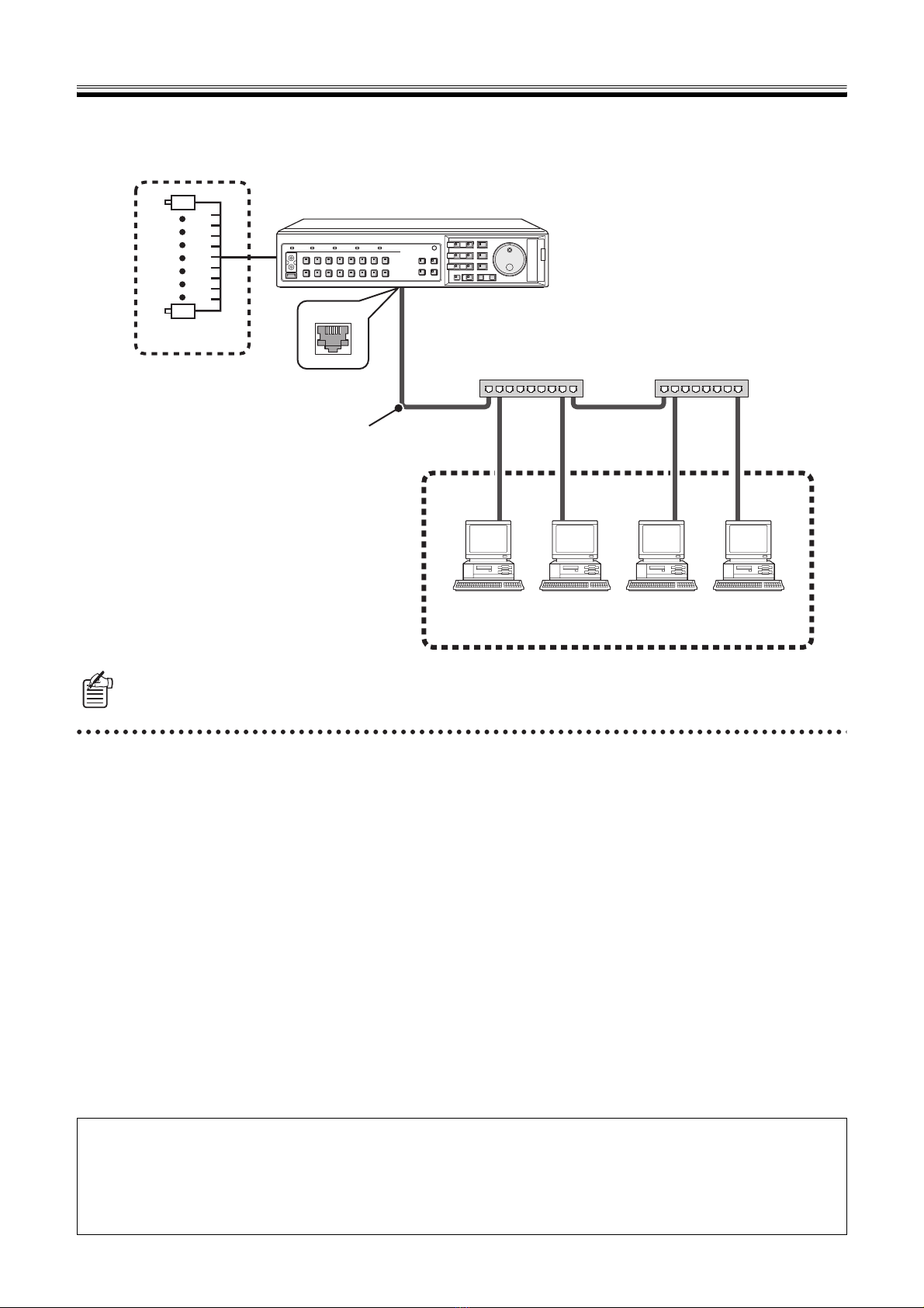
Network Connection Procedure . . . . . . . . . . . . . . . . . . . 3
1NETWORK SET Settings of DVR. . . . . . . . . . . . . . . 3
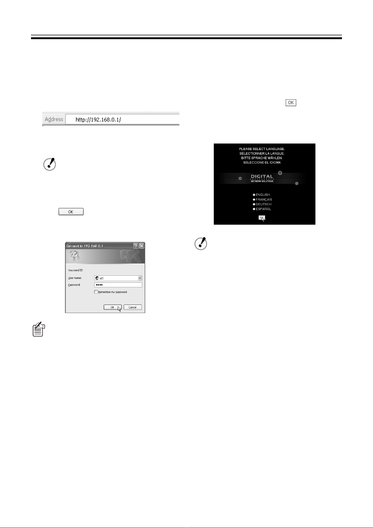
2TCP/IP Settings of the Computer . . . . . . . . . . . . . . . 3
3Network Operation Screen Display. . . . . . . . . . . . . . 5
bNetwork Connection Restrictions . . . . . . . . . . . . . . . 6
bChange to DVR Operation . . . . . . . . . . . . . . . . . . . . 6
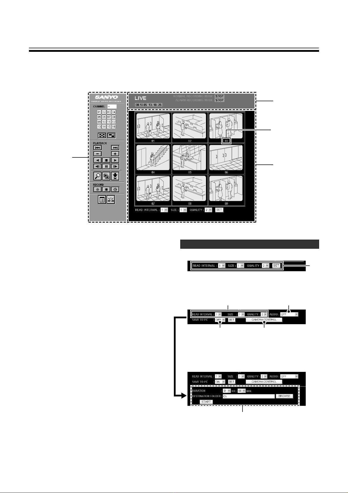
Organization of the Main Screen
and Functions of Each Part . . . . . . . . . . . . . . . . . . . . . . 7
bOrganization of Main Screen . . . . . . . . . . . . . . . . . . 7
1Functions of Operation Panel
and Operation Authority . . . . . . . . . . . . . . . . . . . . . . 8
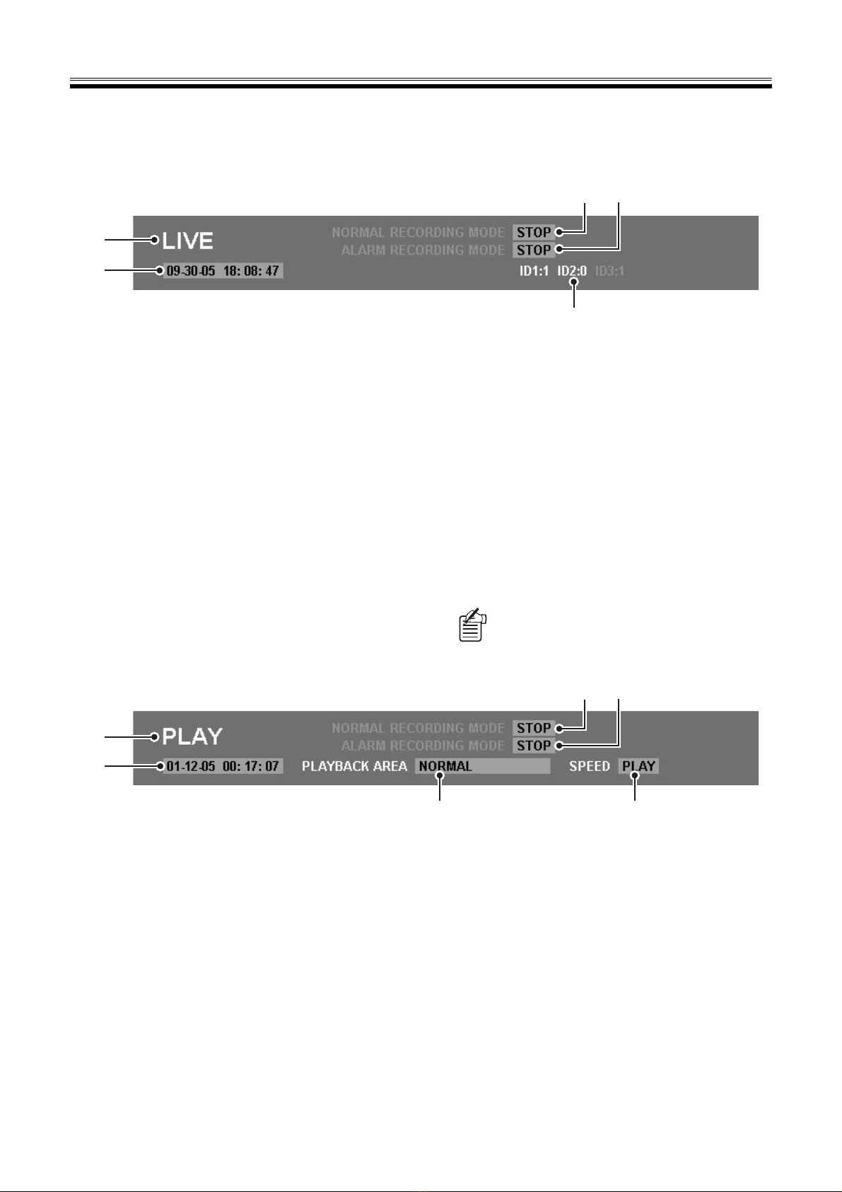
2Operating mode display panel . . . . . . . . . . . . . . . . . 9
View Live Video . . . . . . . . . . . . . . . . . . . . . . . . . . . . . . . 10
1Change display pattern of live video. . . . . . . . . . . . 10
2Set the display mode for images . . . . . . . . . . . . . . 11
3Playback audio . . . . . . . . . . . . . . . . . . . . . . . . . . . . 11
Recording Monitored Images . . . . . . . . . . . . . . . . . . . . 12
bNormal Recording (Normal Recording Area) . . . . . 12
bOther Recording Methods. . . . . . . . . . . . . . . . . . . . 12
View Recorded Images . . . . . . . . . . . . . . . . . . . . . . . . . 13
bPlayback Recorded Images . . . . . . . . . . . . . . . . . . 13
bBasic Playback Operations . . . . . . . . . . . . . . . . . . . 13
Search Recorded Images . . . . . . . . . . . . . . . . . . . . . . . 14
bSearch Screen Selection . . . . . . . . . . . . . . . . . . . . 14
1ALARM SEARCH . . . . . . . . . . . . . . . . . . . . . . . . . . 14
2ALARM THUMBNAIL SEARCH . . . . . . . . . . . . . . . 14
3TIME/DATE SEARCH . . . . . . . . . . . . . . . . . . . . . . . 15
4ARCHIVE AREA SEARCH . . . . . . . . . . . . . . . . . . . 15
5MOTION DETECTION SEARCH . . . . . . . . . . . . . . 16
Saving Images . . . . . . . . . . . . . . . . . . . . . . . . . . . . . . . . 17
ASaving live video on the computer . . . . . . . . . . . . . 17
BCopying Recorded Images
to the DVR’s Archive Area . . . . . . . . . . . . . . . . . . . 18
CDownloading Recorded Images
to the Computer . . . . . . . . . . . . . . . . . . . . . . . . . . . 19
DSaving Format for Image Files . . . . . . . . . . . . . . . . 20
Operating a Dome Camera . . . . . . . . . . . . . . . . . . . . . 21
Setting up the Basic Menu
Using Network Operations . . . . . . . . . . . . . . . . . . . . . . 22
Basic Settings Menu Outline . . . . . . . . . . . . . . . . . . . . 22
Basic menu setting procedure . . . . . . . . . . . . . . . . . . 23
Initial setting. . . . . . . . . . . . . . . . . . . . . . . . . . . . . . . . . . 24
ACLOCK SET . . . . . . . . . . . . . . . . . . . . . . . . . . . . . . 24
BSUMMER TIME SET/EXT. CLOCK SET. . . . . . . . . 24
CHOLIDAY SET. . . . . . . . . . . . . . . . . . . . . . . . . . . . . 24
Recording settings . . . . . . . . . . . . . . . . . . . . . . . . . . . . 25
AARECORDING AREA SET. . . . . . . . . . . . . . . . . . . 25
BRECORDING CONDITIONS SET . . . . . . . . . . . . . 26
CNORMAL REC MODE SET . . . . . . . . . . . . . . . . . . 27
DPROGRAM REC SET. . . . . . . . . . . . . . . . . . . . . . . 28
ETIMER SET. . . . . . . . . . . . . . . . . . . . . . . . . . . . . . . 28
FALARM REC MODE SET . . . . . . . . . . . . . . . . . . . . 30
General settings. . . . . . . . . . . . . . . . . . . . . . . . . . . . . . . 32
ADISPLAY SET . . . . . . . . . . . . . . . . . . . . . . . . . . . . . 32
BBUZZER SET . . . . . . . . . . . . . . . . . . . . . . . . . . . . . 32
CHDD SET . . . . . . . . . . . . . . . . . . . . . . . . . . . . . . . . 33
DNETWORK SET . . . . . . . . . . . . . . . . . . . . . . . . . . . 34
ERS-485 SET . . . . . . . . . . . . . . . . . . . . . . . . . . . . . . 34
Screen settings and DVR information . . . . . . . . . . . . . 35
AMASK SET . . . . . . . . . . . . . . . . . . . . . . . . . . . . . . . 35
BPOWER LOSS/USED TIME . . . . . . . . . . . . . . . . . . 35
CINTIALIZATION LOG . . . . . . . . . . . . . . . . . . . . . . . 35
DVR Viewer2. . . . . . . . . . . . . . . . . . . . . . . . . . . . . . . . . . 36
bOperating Environment . . . . . . . . . . . . . . . . . . . . . . 36
bInstalling the Viewer Software. . . . . . . . . . . . . . . . . 36
bInternet Option Settings . . . . . . . . . . . . . . . . . . . . . 36
bRunning and Quitting Viewer . . . . . . . . . . . . . . . . . 36
bStructure of the Screen and the
Function of each Section . . . . . . . . . . . . . . . . . . . . 37
bOpening Iimage Files . . . . . . . . . . . . . . . . . . . . . . . 38
bSwitching the Display Pattern of the Screen . . . . . . 39
bSelecting the Channel Displayed on the Screen. . . 39
bFunctions of the Viewer Operating Panel . . . . . . . . 40
bSaving and Printing Images . . . . . . . . . . . . . . . . . . 41
bSetting the Date and Time Display Format . . . . . . . 41