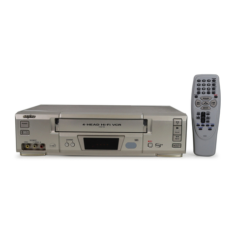
Sanyo HR-VX200 Manual

I
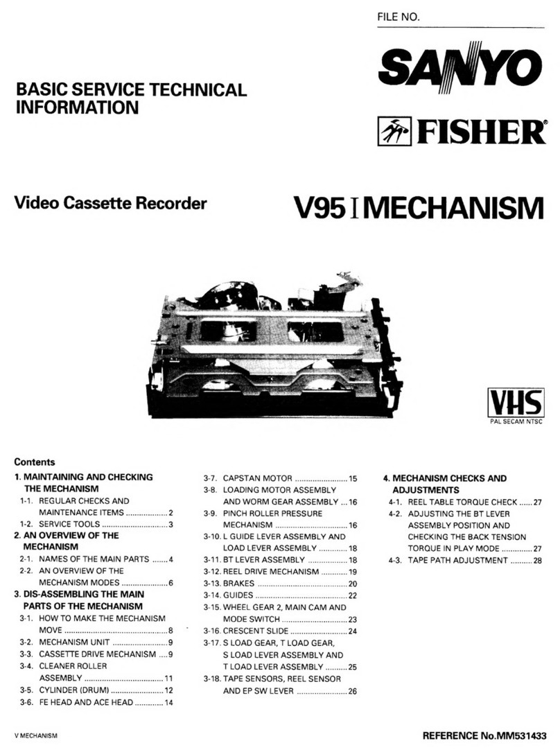
FILE NO.
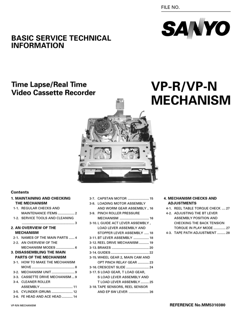
-BASIC SERVICE TECHNICAL
INFORMATION
L
Video Cassette Recorder
S* o
VC MECHANISM
Contents
1. MAINTENANCE AND INSPECTION
OF MECHANISM
1-1. REGULAR CHECKSAND
MAINTENANCE ITEMS ..................2
1-2. SERVICETOOLS .............................3
1-3. CLEANING .......................................4
2. AN OVERVIEW OF MECHANISM
2-1. NAMES OF MAIN PARTS ..............4
2-2. AN OVERVIEW OF
MECHANISM MODES ....................6
3. OPERATING THE MECHANISM
3-1. SERVICE MODE ..............................8
3-2. DRIVING THE LOADING MOTOR
(“assy,motor loading bb VC’’)BY
SUPPLYING DC VOLTAGE ............9
3-3. OPERATING THE MECHANISM
MANUALLY .....................................9
4. DISASSEMBLING THE MAIN
PARTS OF THE MECHANISM
4-1. MECHANISM UNIT ....................... 10
4-2. CASSETTE MECHANISM ............. 11
4-3. COMPL LEVERCLEANER ............14
4-4. CYLINDER (DRUM) ....................... 15
4-5. LEVEREPSW VC .......................... 16
4-6. HEAD ERASE FULL VC................. 17
4-i’.
4-8.
4-9.
ASSY HEAD R/PACE VC.............. 17
PINCH ROLLERDRIVING
SECTION AND ASSY
LEVERLOAD VC ........................... 18
CAPSTAN MOTOR ....................... 19
4-10. GEAR LOCKVC, GEARWHEEL
1/2, CAM MAIN, GEAR RELAY
PINCH VC.......................................2O
4-11. LOADING MOTOR ........................21
4-12. ASSY LEVERBT,
ASSY BRAKEBAND .....................22
4-13. ASSY BRAKES/T VC, COMPL
MOUNTING IDLERVC .................22
4-14. ASSY BRAKESOFT TVC,
TAKE-UP SIDE REELSPINDLE VC,
GEAR REELTVC ..........................23
4-15. SLIDE SOFT SVC, SUPPLY SIDE
REELSPINDLE VC,
GEAR REELSVC ..........................23
4-16. ASSY PULLEY FRICTION VC,
4-17
GEAR CLUTCH VC,
LEVERCLUTCH VC.......................24
LEVERCONTROL BRAKEVC,
COMPL LEVERACT
BRAKEVC......................................25
m
PAL SECAM NTSC
4-18. SLIDE CRESCENTVC ...................25
4-19. ASSY LEVERSPRING BT.............26
4-20. GEAR LOAD S/l, ASSY
LEVERLOAD S/T, MOUNTING
INCL S/T GUIDE VC ......................26
4-21. ASSY ROLLERGUIDE ..................28
4-22. SPRING EARTH VC.......................28
4-23. SPRING GUIDE EARTHVC,
GUIDE SVC...................................28
5. CHECKING AND ADJUSTING THE
MECHANISM
5-1. CHECKINGTHE REELTORQUE
VALUE ...........................................29
5-2. ADJUSTING THE ASSY
LEVERBT POSITION AND
CHECKINGTHE BACKTENSION
TORQUE DURING PLAY ..............30
5-3. ADJUSTING TAPE PATH .............30
VC MECHANISM REFERENCE No. MM531683

1. MAINTENANCE AND INSPECTION OF MECHANISM
1-1. REGULAR CHECKS AND NOTE: OIL AND GREASE
MAINTENANCE ITEMS .Always use the specified brands of oil and grease. If
To obtain full function and maximum performance from you use agrease with the wrong viscosity, for
the set, and to stop it getting dirty or scratched, we example, this can lead to all sorts of problems. Be
recommend that you carry out the following maintenance careful to keep the oil and grease free of dust and
foreign bodies.
procedures and regular checks. The maintenance checks .
described in the following section should also be carried A“drop” of oil is the amount of oil remaining on the
out without fail after carrying out any repairs to the set. tip of arod with adiameter of 1.5mm after it is dipped
in oil to adepth of Icm and then taken out
1-1-1. REGULAR CHECKS oClean 0Check AOil
Hours of use (H)
Part maintained 500 1000 1500 2000 2500 3000 3500 4000 4500 5000 Remarks
Tape guide o0 0 0 0 0 0 0 0 0
Assy, head rlp ace vc o0 0 0 0 0 0 0 0 0
Tape path ~ompi, cylinder XXXX o0000000 0 ‘he ‘ife ‘f ‘arts ‘aries
system enormously, depending on the
(AssY, cylinder, upr XXXX) 0environment in which the part ia
(0) (0) (0) (0) (0) (0) (0) (0) (0) “~e~,
Assy, mounting cleaner o000 0
Assy, lever, pinch vc o0 0 0 0 0 0 0 0 0
Reel, spindle vc oOA oOA o
Drive Belt, reel vc o0QoQo0 0 0 0
system Relay gear, Pulley shaft, Gear shaft AAAAA
Assy, motor loading bb vc o000 0
Back tension o000 0 Playback tension torque:
30 to 50g/cm
Brake system o000 0
Perform-
ance
checks FWD, REW, PLAY torque, FWD: 650g/cm or over
o@o00REW 650g/cm or over
REV (R-SEARCH) torque PLAY (SP mode): 60 to 110g/cm
REV (R-SEARCH): 115 to 180g/cm
Note: The XXXX of the “compl, cylinder, XXXX” display differs according to the model.
-2-

L
L
1-2. SERVICE TOOLS
1-2-1. SERVICE TOOLS
NOTES ON ALIGNMENT TAPES
Select aPAL or NTSC alignment tape from the list below, according to the transmission system of the VCR you are
repairing.
PAL: For models with 625 scanning lines and afield frequency of 50Hz
NTSC: For models with 525 scanning lines and afield frequency of 60Hz
Tool No.
No. Tool Remarks
NTSC PAL
1Alignment tape VHJ-0005 VHJ-OO08 SP colour bar lkHz (normal)
2Alignment tape VHJ-0006 VHJ-0009 SP monoscope 7kHz or 6kHz (normal)
3Alignment tape VHJ-0007 EP monoscope
4Alignment tape VHJ-0052 LP monoscope
5Eccentric screw driver VHJ-0003 Used to adjust the tape path
6Torque dial gauge VHJ-0004 Used to measure reel winding torque
7Cassette torque meter VHJ-0016 Used to measure back tension torque
8
9
10
11
12
13
14
15
Torque gauge screwdriver VHJ-0014 Used to adjust the tightening torque
of screws (2.3 mm dia. bit)
3mm dia. bit for torque screw driver VHJ-0045 Used to replace the bit of the torque
gauge screwdriver
Upper drum fitting tool kit (includes VHJ-01 13) VHJ-0112 Used to reassemble the upper cylinder
Hexagonal wrench VHJ-0113 Spare hexagonal wrench for upper
drum fitting tool kit
Oil VHJ-0099
Grease VHJ-0100
Grease VHJ-0114
Grease VHJ-0115
No.1,2,3,4
No.7
VHJ-0112
‘3
VHJ-011
and
No.10, 11
No.5
NO.8
!No.12
NO.6
No.9
No.13, 14, 15 Fig. 1-2-1
3-

1-3. CLEANING
1-3-1. CLEANING THE CYLINDER (DRUM)
(Refer to Fig. 1-3-l.)
Moisten achamois with methyl alcohol, and clean the
video head. Wipe the chamois in the horizontal direction
on the video head. Take note that wiping it in the vertical
direction or applying excessive force may cause damage
of the video head.
Clean the cylinder surface with chamois or asoft cloth
soaked with methyl alcohol.
1-3-2. CLEANING THE TAPE PATH SYSTEM AND
REEL DRIVING SYSTEM
Clean the pinch roller, capstan shaft, tape guides, “head,
erase full VC”, “assy, head r/p ace VC”, “reel, spindle VC”,
“assy, pulley, friction vc”r “belt, reel”, etc. with chamois
or asoft cloth soaked with methyl alcohol.
Xxxx
Tape path surface
Fig. 1-3-1 -
2. AN OVERVIEW OF MECHANISM
2-1. NAMES OF MAIN PARTS
2-1-1, “COMPL, CASSETTE MECHA VC”
Hood, sensorvc
I(4’QJ
Stand, Ivc ‘1 o
0
0“
a
~ ~
o
0° 00
Guide, cassette Ivc oao
\G#l
OLever, lid )Spring, lid opener vc
P~p/1 Spring, plate vc
\‘Pe?er ‘c i/
Spring, tray vc \v“] /
ve vc
e-.:--
‘w/’’LevedrivervcvcJrd-.-c aprlrly,
Frame under
-
start vc
Fig. 2-1-1
-4-

2-1-2. MECHANISM CHASSIS (UPPER)
Assy, mounting cleaner Motor, capstan dc 3W vc
Motor, stator cyl dc 2W vc
I I Assy, head r/p ace vc
/ I
Ass
As
2-1-3.
Lever, ep sw vc Gear, reel s vc I
Compl, mounting
idler vc
MECHANISM CHASSIS (LOWER)
~MOtO: capstan‘c3WVC A=Tl
Fig. 2-1-2
Gear,
G
t
Spri Vc
GearW~ee12 \Compi,gear, worm \Assy, pulley, friction vc
Gear, wheel 1Assy, motor loading bb vc Fig. 2-1-3
-5-

2-2. AN OVERVIEW OF MECHANISM MODES
2-2-1. MECHANISM MODE SWITCHING TABLE
NOTE: The letters and figures enclosed in the mechanism mode column are the codes on the crescent slide.
MODE SWITCH OUTPUT TABLE
HEX DATA (POSEW 2) (Pos’iw 1) (Pos:w o)
oHHH
I1H H L
2HLH
3HL L
4LH H ,
5LHL
6LLH
7LLL
L: Connected to Cterminal (GND)
H: Not connected to Cterminal (GND)
APPEARANCE OF MODE SWITCH AND
RELATIONSHIP BETWEEN MODE POSITION
INTIAL
IIN REW
EJECT
F/REW
REVIEW
(R-SEARC
E
IDLER I\
PLAY/STOP
STILIJSLOW
Fig. 2-2-1 .—
-6-

2-2-2. MOVEMENT CHECK LIST FOR THE MAIN PARTS OF MECHANISM
MECHANISM MODE ~~
\_ No. K
PRINCIPAL PARTS T
Lu z
—
1Assy, brake tvc OFF OFF
2Assy, brakes vc OFF OFF
3Assy, brake soft tvc OFF OFF
I4ISlide softs vc ION ION
I5IAssv, lever, bt IOFF IOFF
I6ISpring, bt IOFF IOFF
7Assy, lever, pinch vc UP UP
8Gear, clutch vc PLAY PLAY
9Assy, lever load vc UNLO UNLO
10 Assy, brake capstan OFF OFF
‘c 11 Assy, mounting incl s/t vc
12 Assy, mounting cleaner IOFF IOFF
2-2-3. CHECKING THE MECHANISM MODE
POSITIONS
Check the mark for “slide, crescent VC” from the top and
bottom sides of the mechanism to determine the
appropriate mechanism mode position.
LModels with display tubes which come with aservice
mode setting function will indicate HEX DATA on the
display tube. Refer to “3-l-l. SHIFTING TO THE SERVICE
MODE” for more details.
1. CHECKING FROM THE TOP SIDE OF THE
MECHANISM
As shown in Fig. 2-2-2 and Fig. 2-2-3, the “slide, crescent
VC” has marking lines and symbols to indicate the
mechanism modes with the edge of the mechanism
Lchassis as a reference.
The mechanism mode can be determined from the
marking line for the “slide, crescent VC” which matches
the reference line of the mechanism chassis. The HEX
DATA can also be checked from the mechanism chassis
hole.
Note:
●No HEX DATA is indicated for the EJECT mode,
Instead, the hole will be empty.
●No HEX DATA is indicated for the IN REW mode
because it is near the INITIAL mode and so cannot
be indicated. For the same reason, there is also no
marking line for the INITIAL mode.
(S): Strength (W): Weakness
OFF IOFF IOFF IOFF IOFF IOFF IOFF ION ~N/OFI
OFF IOFF IOFF ION ION IOFF IOFF IOFF IOFF
ON ION ION IOFFIOFFIOFF IOFF IOFF IOFF
OFF IOFFIOFF ION ION ION ION ION IOFF
OFF IOFF IOFF 1ON(W)ION(W)10N(S) 10N(S) ]ON(S) ION(W)
UP IUPDOWNIDOWNIUPION IOFF ION ION ]OFF IOFF
‘LAY IPLAY IPLAY IPLAY IPLAY IPLAY IPLAY IPLAY IFF
III1I I 1I
JNLOILO ILOILOILOILO ILO lLO ILO
OFF \OFF IOFF IOFF \ON ION IOFF IOFF IOFF
ILOIUNLOI I I I I I
OFF I(ON) I(ON) IOFF IOFF IOFF ]OFF IOFF IOFF
Take this edge as the reference-line,
Indicates
HEX DATA.
Fig. 2-2-2
L.
L
-7-
Fig. 2-2-3

.
w
2. CHECKING FROM THE BOTTOM SIDE OF THE
MECHANISM
As shown in Fig. 2-2-4, the “slide, crescent VC” has
marking lines and symbols to indicate the mechanism
modes with the edge of the “mounting crescent vc” as a
reference.
The mechanism mode can be determined from the
marking line for the “slide, crescent VC” which matches
the reference line of the “mounting crescent VC”.
In Fig. 2-2-4, as the marking line for 6(FF/REW) matches
the reference line for the “mounting crescent VC”, it
indicates that the mode is the FF/REW mode.
Note:
There is no marking Iineforthe INITIAL mode because it
is near the IN REW mode and so cannot be displayed.
The edge of the “Mounting, crescent VC”
P
H)
Fig. 2-2-4
2-2-4. MALFUNCTION DIAGNOSIS AND
WARNING MESSAGES FOR DROP IN HEAD
OUTPUT
Some models may come with afunction to display
malfunction diagnosis and warning messages when the
head output drops.
Refer to these messages to locate the faulty conditions
and cause of faults during repairs.
For details, refer to the service manuals for the respective
models.
3. OPERATING THE MECHANISM
There are three methods to check mechanism operations;
setting the service mode, applying DC voltage to the
“assy, motor loading bb VC” directly and rotating it,
rotating the “assy, motor loading bb VC” manually.
3-1. SERVICE MODE
The service mode is aspecial mode for services which
allows mechanism operations to be checked and the
cassette tape to be ejected forcibly when it cannot be
removed easily during service repairs using the keys of
the remote controller and main unit.
3-1-1. SHIFTING TO THE SERVICE MODE
1)
2)
3)
With the power ON, continuously press the counter
reset button of the remote controller for more than
15 seconds to set the service mode.
At the same time the service mode is set, the channel
display on the display tube changes to a2-digit
number (HEX DATA in the mode switch output table
described in 2-2-1) indicating the current mechanism
mode position. (Refer to Fig. 3-l-l. )
The service mode can be shifted from all mechanism
modes. (Excluding Power off)
Note 1: Models with no display tubes cannot be
displayed the mechanism mode, but can be
shifted to the service mode.
Note 2: The channel display position on the display
tube differs according to the model.
Indicatesthe
mechanism mode (HEX DATA).
II
-0
I II 17”nn“1-1n
u1! u“ ILlILl‘u u
Fig. 3-1-1
-8-

i
3-1-2. OPERATIONS AFTER SHIFTING TO THE
1)
2)
3)
SERVICE MODE
By continuously pressing the channel button ((+) or
(A)) of the main unit or remote controller, the loading
motor rotates in the loading direction, and the mode
of the mechanism is shifted from the EJECT position
to the FF/REW position of the final mode.
At the same time, the mechanism mode (2-digit
number) currently shifted to is displayed on the
display tube in order. At this time, the drum motor
(“motor, rotor cyl dc 2W VC”) and capstan motor
(“motor, capstan dc 3W VC”) will not rotate.
To shift the mode of the mechanism from the FF/REW
position in the unloading direction (EJECT position
direction), continue pressing the channel button ((-)
or (Y)) of the main unit or remote controller.
At this time, the drum motor will not rotate, but the
capstan motor will rotate in the direction in which
the tape is rewound by the supply reel table.
Continue pressing the PAUSE/STILL button for the
supply reel table ;O wind the tape.
Note 1: To shift in the PLAY, FF/REW directions
without loading the cassette tape, refer to
Fig. 3-1-2, press the “lever, lid opener VC”
~of the “compl, cassette mecha VC” from
the top to release the lock, and make sure
the “stand, IVC” @does not get caught.
@Stand,
pener vc
3-2. DRIVING THE LOADING MOTOR
(“ASSY, MOTOR LOADING BB VC”)
BY SUPPLYING DC VOLTAGE
The loading motor shown in Fig. 3-2-1 (“assy, motor
loading bb VC”) can be driven by supplying DC6V to
DCIIV voltage to its terminals.
1) Disconnect the power plug.
2) Refer to 4-1, and remove the mechanism unit.
3) To rotate in the PLAY and FF/REW directions, connect
the +pole to terminal Aand the -pole to terminal B.
To rotate in the EJECT direction, connect the –pole
to terminal Aand the +pole to terminal B.
Note 1:
Note 2:
To rotate in the PLAY, FF/REW directions,
refer to Fig. 3-1-2, press the “lever, lid
opener VC” @of the “compl, cassette mecha
VC” from the top to release the lock, and
make sure the “stand, iVC” @does not get
caught.
If the loading motor (“assy, motor loading
bb VC”) stops rotating after shifting to the
FF/REW and EJECT modes, stop supplying
the DC voltage.
Arrow indicating EJECT direction.
t
Assy, motor loading bb vc
IVc 3-3. OPERATING THE
1)
2)
Fig. 3-1-2
3-1-3. EXITING THE SERVICE MODE
1) The service mode can be exited by turning off the
power.
2) After exiting the mode, normal operations can be
performed.
Fig.
MECHANISM
MANUALLY
3-2-1
Refer to 4-1 and remove the mechanism unit.
Rotate the loading motor (“assy, motor loading bb
VC”) at the bottom of the mechanism unit with your
finger.
For the unloading direction (EJECT direction), rotate
the loading motor (“assy, motor loading bb VC”) in
the direction of the arrow marked on the loading
motor (“assy, motor loading bb VC”) with your finger.
For the loading direction (FF/REW direction), rotate
in the opposite direction of the arrow. (Refer to Fig.
3-2-l.)
-9-
4. DISASSEMBLING THE MAIN @. Screws
PARTS OF THE MECHANISM @Flexlble 4%7 ~@:cre~s
cable
PRECAUTIONS
●Disassemble and assemble the mechanism in the
EJECT mode.
.Assemble the mechanism in the opposite order of
disassembly referring to “Precautions on Assembly”.
.When removing the mechanism unit from the main
unit, handle it carefully so that the parts do not
damage.
In particular, when the “compl, cassette mecha VC”
is removed to turn over the mechanism, handle it
carefully as the “lever, ep sw VC” may damage easily.
●As plastic clamps are used for preventing the parts
from dislocating, be careful not to apply excessive
force and cause damages.
4-1. MECHANISM UNIT
(Refer to Fig. 4-1-1 to Fig. 4-l-3.)
1) Refer to the service manual of the model to be
2)
3)
repaired and remove the cabinet parts. @Screw I‘~@ Screw
Disconnect the connector 0of the “assy, head rlp 4
ace VC”, flexible cable @of the “motor stator, cyl dc Fig. 4-1-1
2W VC”, and flexible cable @of the “assy, cylinder
Iwr”.
Remove the two screws @I at the bot~om of the
chassis. (’m \
4) Remove the four screws @at the top of the chassis.
To remove the two screws @in front, press down
the “lever, lid opener VC” @of the “compl, cassette
mecha VC” from the top to release the lock, and move
the “tray VC” 0. Be careful not to apply excessive
force to the “tray VC” 0.
5) Lift the mechanism unit @towards the top and
release.
PRECAUTIONS ON ASSEMBLY
1.
2.
3.
4.
When attaching the mechanism unit @, check that
the mode switches on the mechanism unit and CP-I
board are set to the EJECT mode position. (Refer to
Fig. 4-1-2, and Fig. 4-l-3. )
Attaching the mechanism unit @crookedly may
cause damage of the “board to board” connector.
To avoid this, while holding the mechanism unit @
horizontally, fit the two dowels @on the chassis to
the holes and set in place.
Check that the tape sensor is at the designated
position.
Tighten the four screws@ in the following order; right
(rear) +right (front) +left (front) +left (rear).
other.
Fig. 4-1-2
,.-. .
Align the pos
Switch, m
Fig. 4-1-3
-1o-

4-2. CASSETTE MECHANISM
4-2-1. COMPL CASSETTE MECHA [11
(Refer to Fig. 4-2-1.)
1) Remove the two screws ~.
2) Lift the back of the “compl, cassette mecha vc”@
slightly and slide it backwards to remove.
PRECAUTIONS ON ASSEMBLY
1. Fit the two hooks @in front to the two holes @on
the mechanism chassis, adjust the four dowels @to
the four holes @, and attach the “compl, cassette
mecha VC” Q.
At this time, press the “lever, ep sw vcr’~to the front.
(Refer to Fig. 4-2-l.)
2. Tighten the two screws @with atorque of 5.9 to 6.0
kglcm.
@Lever wswvc \\\ ‘1) Iwl “-%Y-+xn
Fig. 4-2-1
-11-

Z
4-2-2. COMPL CASSETTE MECHA [21
1)
2)
3)
4)
5)
6)
7)
8)
9)
(Refer to Fig. 4-2-2 to Fig. 4-2-13.)
Remove the two clamps @and remove the “sensor
hood” ~.
Remove the two clamps @and pull out the “frame
under” @towards the front.
Remove the “spring, start VC” @.
Press the “lever, lid opener VC” @to release the lock,
and remove the “slide, drive VC” @.
Remove the “lever, door opener VC” @.
Remove the two clamps @of the “stand, rVC” 9,
pull out the “stand, IVC” 0, and then remove the
“stand rVC” ~.
Press the tip of the “lever, drive IVC” @to remove it
from the shaft 0of the “guide, cassette IVC” @,
and remove the assembly parts of the “lever, drive I
VC” @/’’lever, drive rVC” @/’’shaft, drive vc”@.
When removing the “lever, drive rVC” @from the
“guide, cassette rVC” @, be careful not to damage
the projection of the shaft @.
Remove the two “spring, tray VC” @.
Remove the “spring, lid opener VC” @.
10) Press the “lever, lid openervc” @in the direction of
the arrow shown in Fig. 4-2-3, remove the two clamps
@l with the notch of the “lever, lid opener VC” @
aligned with the protrusion of the shaft of the “guide, —
cassette rVC” 0, and pull out the “lever, lid opener
Vc” B.
11) Remove the two clamps @shown in Fig. 4-2-3, and
pull out the “guide, cassette rVC” 0.
12) Remove the two clamps @shown in Fig. 4-2-4, and
pull out the “guide, cassette IVC” @.
13) Insert athin slotted screwdriver into the hole @on
the “guide, cassette rVC” 0shown in Fig. 4-2-3 and
remove the clamp @, and pull out the “spring ,plate
VC” @. In the same way, insert athin slotted
screwdriver in the hole @of the “guide, cassette I
VC” @shown in Fig. 4-2-4 and remove the clamp @,
and pull out the “spring, plate VC” @.
14) Remove the screw @shown in Fig. 4-2-2, and remove
the “spring, tray earth VC” @. In almost all models,
the screw @and “spring, tray earth VC” @are not
used.
@Screw
@Spring, tl
earth vc
@Sensor hood
@Guide, cassette Ivc
\
‘Shaf. Z%%<T
?yl d
&Spring, plate vc ,-
@Tray, vc @Leve ‘“
@Spring,
tray vc (& G@Guide, (‘M. ‘
\-i’e cassette r~c ‘> ~I~
?“a*’’v2isi>x&
\
w, IIa opener vc
.*@ SPrin9, lid opener Vc
,rvc
Iide,
Vc
drive vc
@)Clamp
Fig. 4-2-2
-12-

n
L
L
@Spring, plate vc
@ClamD /
<“ @Lever, lid opener vc
@Clamps
@Guide, cassette rvc ,
w
The match position
‘+hg~y;!:;;:n”
!/ La Ild opener
Fig. 4-2-3
@Spring, plate vc
‘=@&<@c’amp
Fig. 4-2-4
PRECAUTIONS ON ASSEMBLY
1. Check that the “spring, plate VC” @and @do not
Lcome off after attaching to the “guide, cassette I/r
VC” @and 0.
2. As shown in Fig. 4-2-5, hook the “spring, lid opener
VC” @to the shaft @properly.
3. Refer to Fig. 4-2-6 to Fig. 4-2-11, and apply grease
(VHJ-0100) to the “stand, r/1 VC” @l and ~, “slide,
drive VC” ~, and “lever, door opener VC” @. (Apply
grease to the shaded parts. )
4. As shown in Fig. 4-2-12 and Fig. 4-2-13, check that
the shafts of the “guide, cassette I/r VC” @and @
and “lever, drive I/r VC” @and @are inserted
properly into the “stand, r/1 VC” @and 0.
Fig. 4-2-12 and Fig. 4-12-13 show the positions of the
shafts in the EJECT mode.
Insert the shafts into the “stand, r/1VC” @and @with
the “tray, VC” @descended.
5. After assembling, move the “slide, drive VC” @
forward and backward, and check that the “tray, Vc’r
L@rises and descends smoothly and the “lever, door
opener VC” @opens and closes smoothly.
L
‘@ Spring, lid opener vc
4
+
/Q
Shaft
&Protrusion
J\
yOK
44NG
Fig. 4-2-5
Apply grease (VHJ-0100) at the inner surface.
0Stand, Ivc Fig. 4-2-6
=a’’’’:’(vHJ
Fig. 4-2-7
@Stand, rvc
1
q-
,
~-~ 0‘\
=“-T :-
Apply grease —~
(VHJ-0100) at the
inner surface. \\ \
Apply grease (VHJ-0100) to the part
in contact with the “slide, drive VC”.
Fig. 4-2-8
-13-

Apply grease (VHJ-O1OO)
to the groove. Apply grease (VHJ-0100) to the side
\ /
/,!to the inner surface.
Apply grease (VHJ-01 00). Stand, rvc
Fig. 4-2-9
@Slide, drive vc
(VI-IJ-0100)
1
Apply grease (VHJ-0100).
Fig. 4-2-10
Apply grease (VHJ-0100).
@Lever, door opener vc
/
k
d
D
Fig. 4-2-11
Shaft of “guide, cassette rVC” @
‘~\+\4~1 .. .. .. ...... .. ....
‘5+~\ 00“(~
/5@--
Qu~
/
v
Shaft of “lever, drive rVC”@
Fig. 4-2-13
4-3. COMPL LEVER CLEANER
(Refer to Fig. 4-3-1.)
1) Remove the cla~p ~, and remove the “lever,
cleaner” @.
2) Remove the clamp @, and remove the “assy,
mounting cleaner” @.
PRECAUTIONS ON ASSEMBLY
1. Be careful not to dirty the “assy, mounting cleaner”
a.
2. When attaching the “lever, cleaner” @, hold the
clamp 0with the plastic spring @pressed against
the stopper @and attach.
—
.
B
@Assy, mounting cleaner ~@ Clamp
L@Lever, cleaner
@Stopper
Fig. 4-3-1
~Stand, Ivc Shaft of “guide, cassette IVC” @I
“~
or
o
p~ D
00 0
~“
Shaft of “lever, drive IVC”@
Fig. 4-2-12
-14-

m
.
4-4. CYLINDER (DRUM)
(Refer to Fig. 4-4-1 to Fig. 4-4-3.)
4-4-1. CYLINDER (DRUM) MOTOR, ASSY
\- 1)
2)
3)
4)
“L
5)
CYLINDER UPR XXXX
Disconnect the flexible cable @connected to the
“motor, stator, cyl dc 2W VC” 0.
Remove the two screws @, and remove the “motor,
stator, cyl dc 2W VC” 0, and “spring, earth cylinder”
@.
In this state, the “earth chip cylinder” @will fall off
if the top and bottom of the mechanism unit are
reversed.
Note: “earth chip cylinder” @can be removed by
removing the “mounting motor, cylinder” @
in step 4).
Remove the two screws @and remove the “motor,
rotor, cyl dc 2W vcr’ a.
Loosen the screw@ with the hexagonal wrench, and
remove the “mounting, motor, cylinder” ~.
Note: The hexagonal wrench (VHJ-0113) is 2mm
diagonally. It is provided with the servicing
tool upper drum fitting tool kit (VHJ-0112)
Remove the “assy, cylinder, upr XXXX” @and the
“spacer, cylinder” ~.
The “spacer, cylinder” ~may come off attached to
the “assy, cylinder, upr XXXX” @.
Note: The XXXX of the “assy, cylinder, upr XXXX”
display differs according to the model.
PRECAUTIONS ON ASSEMBLY
1.
L
2.
L
3.
4.
5.
Adjustments are required when attaching the
“mounting, motor, cylinder” @. As shown in Fig. 4-
4-2, face the protruded side of the “mounting motor,
cylinder” @downwards, and with the hexagonal
wrench pressed to screw @, adjust the position of
the “mounting motor, cylinder” in the direction of
the screw ~. In this state, hold the “mounting, motor,
cylinder” 0with the upper drum fitting tool (VHJ-
0112) and tighten the screw @with the hexagonal
wrench.
When attaching the “motor, rotor, cyl dc 2W VC” o,
the phase must be adjusted to that of the “assy,
cylinder, upr XXXX” @. As shown in Fig. 4-4-3, attach
so that the hole @of the “assy, cylinder, upr XXXX”
@I and hole @of the “motor, rotor, cyl dc 2W VC” 0
are on the same side.
Tighten the two screws @for attaching the “motor,
rotor, cyl dc 2W VC” @and the two screws @for
attaching the “motor, stator, cyl dc 2W VC” ~using a
torque of 2.5 to 3.5 kglcm.
Be careful that the tape path surface of the cylinder
(drum) does not scratch or become dirty.
If it becomes dirt, clean.
After attaching, refer to “5-3. Adjusting Tape Path”
and the section on electrical adjustments in the
service manuals for the respective models, and
adjust the switching position of the servo circuit.
@Screws @Flexible cable
1.
1> I
~@)Motor, stator, cyl dc 2W vc
2~@Motor, rotor,
\- Cyl dc 2W VC
-
/=~ \
@Mounting, motor, cylinder
@Spring, earth
cylinder /& &-~.
@Earth chip cylinder ‘r@=’@ ’crew
&
F\
Qo@As;yi~y~~der,
Fig. 4-4-1
/Upper drum
%!!lI ~
\
fitting tool
(W+J-0112)
9Mounting, motor,
“A-
u
cylinder B’oscrew
wrench
0Scre
Fig. 4-4-2
-15-

?)
0°0
@Assy, cylinder,,
0)
o0
upr XXXX Ob o~
o
o~ O.O
00
~Motor, rotor,
cyldc2wvc \e
@Hole
@Hole
Fig. 4-4-3
4-4-2. COMPL CYLINDER XXXX
(REFER TO FIG. 4-4-4.)
1) Refer to 4-1 and remove the mechanism unit.
2) Refer to 4-4-1 and remove the “motor, stator, cyl dc
2W Vc” ,“motor, rotor, cyl dc 2W VC”, “spring, earth
cylinder”, and “earth chip cylinder”.
3) Remove the three screws @at the bottom of the
mechanism and remove the “compl, cylinder XXXX”
Q.
Note: The XXXX of the “compl, cylinder, XXXX”
display differs according to the model.
PRECAUTIONS ON ASSEMBLY
1.
2.
3.
4.
5.
Be careful that the tape path surface of the cylinder
(drum) does not scratch or become dirty.
If it becomes dirt, clean.
Adjust the “compl, cylinder XXXX” @to the two
dowels @of the mounting part of the mechanism
chassis.
Tighten the three screws @with a3.9 to 4.2 kg/cm
torque.
There is aneed to adjust the phase to the “assy,
cylinder, upr XXXX” when attaching the “motor,
rotor, cyl dc 2W VC”.
As shown in Fig. 4-4-3, attach so that the hole @of
the “assy, cylinder upr XXXX” @and hole @of the
“motor, rotor, cyl dc 2WVC” @are on the same side.
After attaching, refer to “5-3. Adjusting Tape Path”
and the section on electrical adjustments in the
service manuals for the respective models, and
adjust the switching position of the servo circuit.
@Compl, cylinder XXXX
Fig. 4-4-4
4-5. LEVER EP SW VC (Fig. 4-5-l.)
1) Refer to 4-2-1, and remove the “compl, cassette
mecha VC”.
2) Remove the “spring, ep sw VC” ~.
3) Press the two clamps @and remove the “lever, ep
Sw Vc” a.
PRECAUTIONS ON ASSEMBLY
1. Make sure that the clamps @are hooked properly to
the “lever, ep sw VC” @.
P
@Lever,
@c
Vc
—
-
Fig. 4-5-1 ----..’
-16-

i
4-6. HEAD ERASE FULL VC
(Refer to Fig. 4-6-1.)
1) Remove screw ~.
2) Remove the “head, erase full VC” @.
‘i PRECAUTIONS ON ASSEMBLY
1. Tighten the three screws @with a6.0 to 7.0 kg/cm
torque.
2. Be careful that the tape path surface does not scratch
or become dirty. If it becomes dirt, clean.
l_-
4-7. ASSY HEAD R/P ACE VC
(Refer to Fig. 4-7-l.)
1) Remove screw ~.
2) As shown in Fig. 4-7-1, press the “assy, head r/p ace
VC” @in the arrow direction and then remove
upwards.
PRECAUTIONS ON ASSEMBLY
1. Adjust the hole @of the “assy, head rlp ace vcr’ ~
to the position of the pin @of the mechanism
chassis,
2. Tighten the screw @with a4.0 to 5.0 kg/cm torque.
3. After attaching, check that clamp @of the “lever,
cleaner” is hooked to the mounting part of the “assy,
head r/p ace VC” @.
4. Be careful that the tape path surface does not scratch
or become dirty. If it becomes dirt, clean.
5. After attaching, refer to “5-3. Adjusting Tape Path”
and adjust the tracking (X value).
@Assy, head rlp ace vc
@Screw,
Fig. 4-6-1
Fig.
Hole
4-7-1
“L
‘L
-17-

m
4-8. PINCH ROLLER DRIVING SECTION
1)
2)
3)
4)
5)
6)
7)
8)
AND ASSY LEVER LOAD VC
(Refer to Fig. 4-8-1 to 4-8-7.)
Remove the “spring, pinch roller VC” @.
Remove the “assy, lever, pinch VC” @.
Press the clamp @of the “mounting, opener VC” ~,
and remove the “mounting, lift pinch VC” @.
Remove the screw @.
Remove the clamps @and @, and remove the
“mounting, opener vc” 0.
Remove the “gear, cam pinch VC” ~.
Remove the washer @, and remove the “assy, lever
load VC” @and “spring, lever load VC” @.
Slide the “gear, rack pinch VC” ~in the rear direction
fully and then remove it.
PRECAUTIONS ON ASSEMBLY
1.
2.
3.
4.
5.
6.
Refer to Fig. 4-8-2 to Fig. 4-8-5, and apply grease
(VHJ-0100) to the “gear, rack pinch VC” @, “gear, cam
pinch VC” @r “mounting, opener VC” ~, and sliding
parts of the mechanism chassis. (Apply grease to the
shaded parts. )
After attaching the “gear, rack pinch VC” @, slide it
until it touches the front.
Refer to Fig. 4-8-6, and insert one end of the “spring,
lever load VC” @into the hole~ of the outserter and
hook the other end to the “assy, lever load VC” ~.
Refer to Fig. 4-8-7, and align the Amark to the “gear,
cam pinch VC” @and “gear, relay pinch VC” @.
Tighten the screw @with a5.0 to 6.0 kglcm torque.
Check that the clamps @and @of the “mounting,
opener VC” @are hooked properly to the mechanism
chassis. Check that the clamp @is hooked properly
to the “mounting, lift pinch VC” ~.
Ier vc
c
Vc
hVC
Apply
to the
@Gear, rack pinch vc
Fig. 4-8-2
grease
side.
@l Gear, cam pinch
I
Fig. 4-8-3
@Mounting, opener vc
1
Apply grease
Fig. 4-8-4
Fig. 4-8-1
-18-

.
m
L
Apply grease (VHJ-01 00)
rad to the bottom of the clamp
Fig. 4-8-5
@Hole
3
\-@Spring, lever
load vc
9@
,/.”--- ..+
,’ ‘i
-... :
-%.-$, ,’
..*. ---..,
\~Assv, lever load vc
Fig. 4-8-6
@Gear, cam pinch vc
Align the position 01
of the Amark.
@Gear, relay
pinch vc
4-9. CAPSTAN MOTOR
4-9-1. ASSY BRAKE CAPSTAN
(REFER TO FIG. 4-9-l.)
1) Remove the “spring, brake capstan” ~.
2) Remove the clamp ~, and remove the “assy, brake
capstan” Q.
PRECAUTIONS ON ASSEMBLY
1. Check that the clamp @is hooked properly to the
mechanism chassis .
@Spring, brake capstan
\1
@Assy, brake \=$$9
capstan @
\lfl
@Clamp. -~!.l~ml
4Rxs-
~-A J)FL---=
0
Fig. 4-9-1
“L
“L
Fig. 4-8-7
-19-

.
.
4-9-2. MOTOR CAPSTAN DC 3W VC
(REFER TO FIG. 4-9-2.)
1) Refer to 4-1 and remove the mechanism unit.
2) Remove the “belt, reel VC” @at the bottom of the
mechanism unit.
3) Remove the screw @, and remove the “mounting
capstan” @.
4) Remove the three screws@, and remove the “motor,
capstan dc 3W VC” @.
PRECAUTIONS ON ASSEMBLY
1.
2.
3.
Tighten the three screws @in the order of a, b, then
cwith atorque of 3.25 to 3.75 kglcm.
Insert the protruded part @of the “mounting
capstan” @into the hole @of the mechanism
chassis.
Be careful that the capstan shaft does not scralch or
become dirty. If it becomes dirt, clean.
@Screws
\\
$? “C
mHole l>. ,/ ‘1
)> 1
‘g:&
&
e7’
*@
Protruded part
&
@Motor, capstan Id i~.,~@Mounting
dc 3W VC capstan
=.,et-”cFig. 4-9-2
4-10. GEAR LOCK VC, GEAR WHEEL 1/2,
CAM MAIN, GEAR RELAY PINCH VC
(Refer to Fig. 4-10-1 to Fig. 4-10-3.)
1) Refer to 4-1 and remove the mechanism unit.
2) Remove the clamp~ at the bottom of the mechanism _
unit, and remove the “gear, lock VC” @.
3) Remove the clamp @, and remove the “gear, wheel
2“ @.
4) Remove the “special washer” ~, and remove the
“cam main” @.
5) Remove the clamp ~, and remove the “gear, wheel
1“ B.
6) Remove the clamps @and@, and remove the “gear,
relay pinch VC” ~.
PRECAUTIONS ON ASSEMBLY
1. Apply grease (VHJ-0100) to the shaded part@ in Fig.
4-10-2, and grease (VHJ-0114) to the shaded part @.
2. Apply grease (VHJ-0100) to the teeth of the “gear,
wheel 2“ @, “gear, wheel 1“ @, “cam main” ~, and
“gear, lock VC” @. Also apply grease to the groove
of the “cam main” @.
3. As shown in Fig. 4-10-3, align the gear phase of the -
“gear, relay pinch VC” ~, “gear, wheel 2“ @, “gear,
wheel 1“ @, “cam main” @, and “gear, lock VC” @.
,0 Special washer
.@
“’amp+=e -
@Gear,
wheel 1(“/
the
—.
Fig. 4-10-1
-20-
Table of contents
Other Sanyo VCR System manuals

Sanyo
Sanyo VHR-VX800 User manual

Sanyo
Sanyo VHR-7100 User manual

Sanyo
Sanyo VHR-H631 User manual

Sanyo
Sanyo VHR-590 User manual

Sanyo
Sanyo 5300 - SCP Cell Phone User manual

Sanyo
Sanyo VWM-950 User manual

Sanyo
Sanyo VHR-450 User manual

Sanyo
Sanyo VWM-800 User manual

Sanyo
Sanyo VHR-150 User manual

Sanyo
Sanyo TLS-224P User manual

Sanyo
Sanyo VHR-810 User manual

Sanyo
Sanyo TLS-9960 User manual

Sanyo
Sanyo VHR-274G User manual

Sanyo
Sanyo VHR-330EV User manual

Sanyo
Sanyo VHR-810 User manual

Sanyo
Sanyo VHR-VK310A User manual

Sanyo
Sanyo VHR-390 User manual

Sanyo
Sanyo VHR-420 User manual

Sanyo
Sanyo FISHER V95 I Mechanism Manual

Sanyo
Sanyo SRT-8040 User manual