Sartorius stedim 16694-2-50-06 User manual

85032-535-33
Operating Instructions | Bedienungsanleitung | Mode d'emploi
Istruzioni per l’uso | Instrucciones de manejo
Laboratory Vacuum Pumps | Labor Vakuumpumpen |
Pompes à vide de laboratoire | Pompe a vuoto da
laboratorio | Bombas de vacío para laboratorio
16694-2-50-06
16694-1-60-06

English Page 3
Deutsch Seite 13
Français page 23
Italiano pagina 33
Español página 43
2

3
1. Description,
Operating Conditions 4
2. Safety 4
3. Installation 4
4. Operation 5
5. Servicing 5
6. Cleaning 7
7. Trouble Shooting 7
8. Replacement Parts 8
9. Tables 8
Appendix 9
List of Contents
You have selected a high-quality Sartorius
Stedim Biotech product; the following tips
will help you operate it safely, and reliably
over a long period of time. Carefully study
the operating instructions before using the
pumps and observe at all times the relevant
instructions to avoid dangerous situations.
Symbols
Position in the illustration
– Important point
Task
• Advise to users
!Warning
Sartorius Stedim Biotech reserve
the right to make changes

4
1. Description, 2. Safety 3. Installation
Operating Conditions
– Note that the pumps may only be
used for their intended purpose.
The pumps must not be used in
areas where there is a danger of
explosion.
– For vacuum pumps: The gas dis-
charge at the pressure side must
be drained off safely and reliably.
Components connected to the
pumps must be designed to with-
stand the pneumatic performance
of the pumps (see table 2).
– Plug the pump only into properly
installed grounded outlets.
When the operation of the pump is
interrupted by the thermal switch,
the pump will re-start automatically
after cooling down. Take all care
necessary to prevent this leading to
a dangerous situation.
Specific safety instructions and
measures for the media being
handled must be observed.
– Use only original Sartorius Stedim
Biotech spare parts.
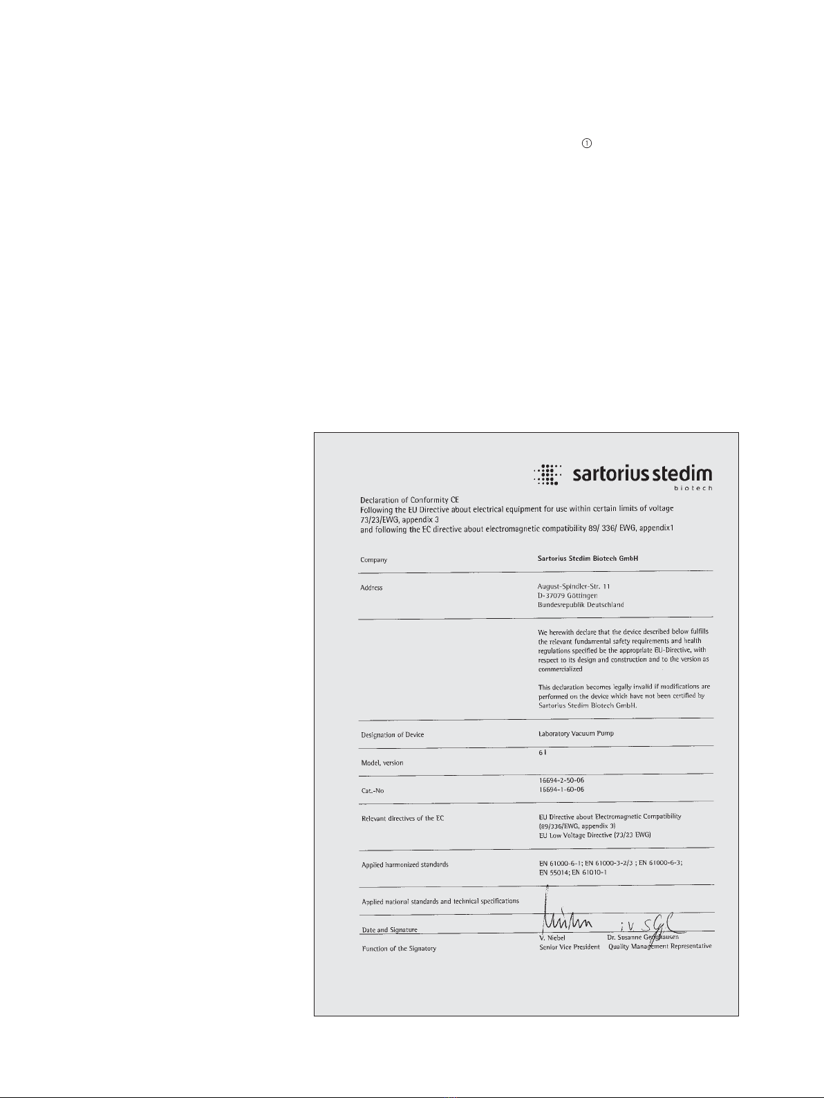
• The pumps conform to the safety
regulations of the EC Low Voltage
Directive 73/23 EEC, and of the EC
Directive 89/336 EEC concerning
Electromagnetic Compatibility.
The requirements of the following
harmonized standards are fulfilled:
EN 61010 part 1, EN 61000-6-1,
EN 61000-6-3.
– Choose a safe location (flat surface)
for the pump.
– Install the pump so as to ensure
adequate flow of air cooling.
– Fit the pump at the highest point
in the system, so that condensate
cannot collect in the head of the
pump – that prolongs working life
of structured diaphragm and pump.
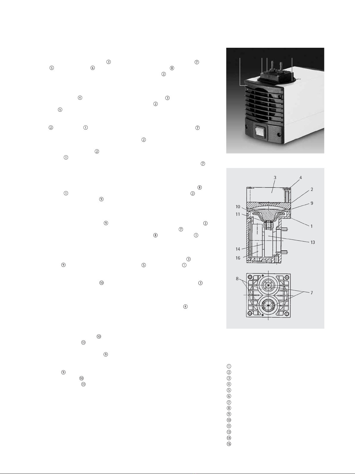
– At the pump head, remove the
protection plugs from the hose
connectors.
– Mounting the accessory parts filter
or silencer (if present): If the pump
is used as a vacuum pump, mount
a silencer at the pressure side if
necessary. If the pump is used as
a compressor, mount a filter at the
suction side if necessary.
• Before mounting the filter or
silencer, unscrew the corresponding
hose connector from the threads in
the pump head.
– Connect the suction and pressure
lines (tube ID 4 mm). For flow
direction see marking on the pump
head.
– Arrange the suction and pressure
lines so that condensate cannot run
into the pump (sloping lines).
– For vacuum pumps: The gas dis-
charge at the pressure side must
be drained off safely and reliably.
– Plug the pump only into properly
installed grounded outlets.
– Compare the supply data with the
electrical data of the pump. The
voltage must not vary by more than
+10% and –10% from that shown
on the type-plate.
The pumps transfer, evacuate and
compress 100% oil-free.
1.1 Electrical Equipment
– See table 1 for full electrical data.
– The protection class of standard
versions is IP 20.
– The pumps are fitted with a thermal
– switch to protect against over-
loading.
1.2 Operating Conditions
– Handling air, gases, and vapours
at temperatures between
+5°C … +40°C.
– For maximum permissible operating
pressure, ultimate vacuum, and
flow capacity: see table 2.
The pumps must not be used in
areas where there is a danger of
explosion.
– The pumps must not be used for
liquids.
– Before pumping a medium, the
compatibility of materials of pump
head, diaphragm and valves with
the medium must be checked
(for pump materials: see table 3).
– Pumps that may be employed as
vacuum pump and compressor
must not be used to produce
vacuum and pressure at the same
time.
If your potential application lies
outside the above limits discuss it
with our technical adviser (see last
page for contact address).
1.3 Ambient Condition
When the pumps are operating the
following ambient conditions must
be maintained:
– Ambient temperature during
operation: between +5°C … +40°C.
– During operation an adequate
supply of air for cooling must be
provided.
– The pumps must not be used in
areas where there is a danger of
explosion.
1.4 Pump materials
See table 3.
!
!
!
!
!

5
4. Operation 5. Servicing
– When the pump is at a standstill
the inlet and exhaust must be at
normal atmospheric pressure.
– Change the filter (accessory) if it
is dirty.
– Pumps that may be employed as
vacuum pump and compressor
must not be used to produce vacu-
um and pressure at the same time.
– Diaphragm and valve plates are the
only parts subject to wear. Wear is
usually indicated by a drastic reduc-
tion in the pneumatic performance
(vacuum, pressure, delivery). When
replacing parts proceed as described
in section 5.
– Ambient conditions: see chapter
1.3.
Before working on the pump,
disconnect it from the electricity
supply by pulling the plug out.
• Diaphragm and valve plates are
the only parts subject to wear.
They are simple to change.
• Always change valve plates,
diaphragm, and sealing rings at the
same time. If the diaphragm and
the valve plates are not changed
at the same time the nominal
performance of the pump is not
guaranteed after the service.
• If aggressive, toxic or other types
of gases hazardous to health have
been pumped please observe:
1.) Clean the pump and its compo-
nents before servicing.
2.) Ensure that the service personnel
is not subject to a health hazard
during diaphragm and valve plate
changes. Apply the necessary safety
measures (example: the use of
protective gloves).
3.) Ensure that the discarded parts and
materials are safely and correctly
disposed of.
Parts|tools required
– Service Set (see section 8)
– Philips-head screwdriver No. 1
– Small screwdriver
– Pencil
Changing the structured diaphragm,
valve plates, and sealing rings in the
following sequence:
a) Remove pump head
b) Change structured diaphragm
c) Change valve plates and sealing
rings
d) Refit pump head
See figs. 4 and 5.
– The pumps can be switched on and
off using the power switch.
Specific safety instructions for the
media being handled must be
observed.
– Before pumping a medium, the
compatibility of materials of pump
head, diaphragm, and valves with
the medium must be checked (for
pump materials: see table 3).
– The pumps must not start against
pressure or vacuum. This also
applies when the pump restarts
after the power has been cut off
for a short period. If a pump starts
under pressure or vacuum, then
the thermal switch will be activated
and switch the pump off.
When the operation of the pump is
interrupted by the thermal switch,
the pump will re-start automatically
after cooling down. Take all care
necessary to prevent this leading to
a dangerous situation.
The maximum permissible operat-
ing pressure (see table 2) must not
be exceeded.
– To prevent the maximum permis-
sible operating pressure being
exceeded, restriction or control of
the air or gas flow should only be
carried out in the suction line.
– If restriction or control of the air
or gas flow is made on the pressure
side ensure that the maximum per-
missible operating pressure is not
exceeded. Excessive pressure (with
all of the related hazards) can be
prevented by placing a bypass line
with a pressure-relief valve between
the pressure and suction sides of
the pump. For further information,
contact our specialists (contact
address: see last page).
!
!
!
!

6
a) Removing pump head
Mark the position of head plate ,
cover and cover plate relative
to each other by a drawing line
with a pencil. This helps avoid
incorrect assembly later.
Undo the 4 screws in the head
plate and lift the head plate with
the cover off the pump housing.
Mark the position of intermediate
plate and housing relative to
each other by a drawing line with
a pencil.
Lift the intermediate plate off
the housing .
b) Change structured diaphragm
Using a small screwdriver, between
the housing and the outer edge
of the structured diaphragm ,
carefully lever the edge of the
diaphragm lightly upwards.
Grip the structured diaphragm
on opposite sides, unscrew it about
two turns (anti-clockwise).
Hold the pump with one hand,
so that the head is pointing
downwards. Turn the structured
diaphragm anti-clockwise to
unscrew it.
Take the diaphragm support
and diaphragm spacer(s) k off the
threaded portion of the diaphragm
and retain them.
Check that all parts are free from
dirt and clean them if necessary
(see section 6. Cleaning).
Put the diaphragm support and
diaphragm spacer(s) , in that
order, on the threaded portion of
the new structured diaphragm .
Screw the new structured
diaphragm , complete with
diaphragm support and
diaphragm spacer(s) into the
connecting rod (clockwise) and
tighten it by hand.
c) Changing the valve plates
Remove the valve plates and
sealing rings from the intermedi-
ate plate (sealing rings could
cling to the head plate).
Check that the valve seats in the
head plate and intermediate
plate are clean. If scratches or
distortion are evident on these
parts they should be replaced.
Lay the new valve plates in the
recesses in the intermediate plate
. The valve plates for suction and
pressure sides are identical, as are
upper and lower sides of the plates.
Check that the valve plates are
not deformed by moving them
gently sideways in their recesses.
Lay the new sealing rings on
the intermediate plate .
d) Refitting the pump head
Place the intermediate plate ,
with valve plates and sealing
rings on the housing , in the
position indicated by the drawing
line.
Place the head plate , with cover
on the housing , in the posi-
tion indicated by the drawing line.
Check that the head plate
is centred by moving it gently
sideways.
Tighten the screws , evenly and
diagonally, first gently, then firmly.
• If you have any questions about
servicing call our technical adviser
(see last page for contact address).
Specification
Housing
Intermediate plate
Head plate
Screw
Cover
Cover plate
Valve plate
Sealing ring
Structured diaphragm
Diaphragm support
Diaphragm spacer(s)
Connecting rod
Eccentric
Counter weight
6 4 3 5
Fig. 4: Pump parts
Fig. 5: Pump parts

7
6. Cleaning 7. Trouble Shooting
Before working on the pump isolate
the power supply securely, then
check that the lines are not live.
• The following tips for fault-finding
are best employed in the sequence
shown.
Pump produces no flow
– Thermal switch has opened due to
over-heating.
• Disconnect pump from mains
and allow to cool. Trace cause of
over-heating and eliminate it.
– Fuses in the pump are defective
(only authorized|qualified person-
nel should investigate this problem)
• Remove the pump from the source
of electrical power by pulling the
power plug.
• At the pump housing, fuses are
located at the IEC plug.
• Fuse ratings: see Table 1.
• Order numbers for fuses: see
Chapter 8.
– Connections or lines are blocked.
– An external valve is closed,
or a filter blocked.
– Liquid (condensate) has collected
in the pump head.
• Let the pump run for a few minutes
pumping air.
• Install the pump at the highest
point in the system.
– Diaphragm or valve plates are worn.
• Section 5 Servicing.
– When changing structured
diaphragm and valve plates, inspect
all parts for dirt before assembling
the pump head and clean them if
necessary.
– As far as possible, clean the parts
with a dry cloth. Only use solvents
for cleaning if the head materials
cannot be attacked (check the
resistance of the material!).
!Flow, pressure, or vacuum too low
– Compare the actual performance
with the figures in table 2.
– There is pressure on the pressure
side, and at the same time vacuum,
or a pressure above atmospheric,
on the suction side.
• Change pneumatic conditions.
– Liquid (condensate) has collected
in the pump head.
• Let the pump run for a few
minutes pumping air.
• Install the pump at the highest
point in the system.
– The cross-section of pneumatic
lines, or connected components is
too small, or they are restricted.
• To measure the performance,
disconnect the pump from the
system (small diameter tubing or
a valve can significantly affect
performance).
– There is a leak at a connector,
in a line, or in the pump head.
– Diaphragm or valve plates are worn,
or dirt is in the head.
• Section 5 Servicing.
• If the pump does not operate
properly and you cannot find any
of the above faults, send it to the
Sartorios Service Department.
• In order for Sartorius Stedim
Biotech to repair the pump, the
customer must provide a statement
on the media which were pumped
and on pump cleaning. Please fill
out the corresponding Sartorius
Stedim Biotech form, and submit it
together with the pump. A sample
statement for copying can be found
in the Appendix of these operating
instructions.

A Service Set contains all replace-
ment parts needed for one
complete service: 1 structured
diaphragm, 2 valve plates and
2 sealing rings.
Order-No.
1ED----0054
Fuses
There are two fuses for each pump.
Electrical Order-No. fuse
Version (1 piece)
230 V 025250
115 V 029986
100 V 020085
Table 1: Electrical Data
Electrical Type
Voltage 230 V 115V
Frequency 50 Hz 60 Hz
Power consumption 65 W 60 W
Operating current 0.63 A 1.2 A
Fuse* (2+) T (A)
* Order-No. see section 8
Table 2: Pneumatic Data
Delivery Ultimate vacuum Maximum permissible
(l/min*) (mbar abs) operating pressure
(bar g)
6 100 2.4
* Litre at SPT at atm. pressure
Table 3: Pump materials
Pump head Structured Valves
diaphragm
PPS EPDM FPM
Material abbrevations according to DIN ISO 1629 and 1043.1
8. Replacement Parts 9. Tables
8

9
• In order for Sartorius Stedim Biotech to repair the pump, the customer must provide
a statement on the media which were pumped and on pump cleaning. Please fill out
the corresponding Sartorius Stedim Biotech form, and submit it together with the
pump.
Statement|Certificate
We confirm that the pump model listed below (please specify)
Serial-No. (please specify)
was used to pump the following media:
and that the pump listed above was cleaned. There are no poisonous, aggressive,
biological, radioactive or other dangerous media in the pump.
Company Date|Signature
Appendix: Customer statement for repair order
(sample statement for copying)
Packaging that is
no longer required
must be disposed of
at the local waste
disposal facility. The
packaging is made
of environmentally
friendly materials
that can be used as secondary raw
materials.
The equipment, including acces-
sories and empty non-rechargeable
and rechargeable batteries, does not
belong in your regular household
waste; such equipment is manu-
factured from high-grade materials
and can be recycled and reused.
The European Directive 2002/96/EC
on Waste Electrical and Electronic
Equipment (WEEE) requires that
electrical and electronic equipment
be collected and disposed of sepa-
rately from other unsorted municipal
waste with the aim of recycling it.
The crossed out waste bin symbol
indicates that separate collection
is required.
In Germany and many other
countries, Sartorius AG takes care
of the return and legally compliant
disposal of its electrical and elec-
tronic equipment on its own. Such
equipment may not be thrown out
with household waste or brought
to collection centers run by local
public disposal operations – not
even by small commercial operators.
Please contact our on-site service
technicians or our Service Center in
Goettingen:
Sartorius AG
Service Center
Weender Landstrasse 94-108
37075 Goettingen, Germany
Tel.: +49.551.308.3333|4444
Fax: +49.551.308.3730
E-Mail:
Information and
Instructions on Disposal

10
For equipment disposal in the
following countries of the European
Economic Area (EEA), please con-
tact your local Sartorius subsidiary
or distributor:
Austria
Sartorius Ges.m.b.H. Wien
Harri Thenmaier
Tel.: +43.1.796.57.63
Fax: +43.1.796.57.6344
E-mail:
Belgium
Sartorius Technologies n.v.
Tel.: +32.2.756.06.80
E-mail:
Cypress
Markides & Vouros Ltd.
Klitos Theocharides
Tel.: +357.22.442822
E-mail:
Czechia
Sartorius Service and
Consulting Center
Karolina-Express
Tel.: +420.47.520.08.70|521.1348
Fax: +420.47.520.08.70
E-mail: [email protected]
Denmark
Sartorius A/S
Tel.: +45.70.23.44.00
E-mail:
Estonia
Sartorius Service and
Consulting Center
OÜ Perimex
Tel.: +372.6.726.777
Fax: +372.6.726.778
E-mail: [email protected]
Finland
Sartorius Ltd
Sally Brotherwood
Tel.: +44.1372737117
E-mail:
France
Sartorius S.A.
Jean-Marie Poitrot
Tel.: +33.1.69.19.21.19
E-mail:
Greece
Biodynamics SA
Constantin G. Liatsos
Tel.: +30.210.6449421
E-mail: http://www.biodynamics.gr
Hungary
Sartorius Service and
Consulting Center
S-Membran Kereskedelmi es
Szolgaltato Kft.
Tel.: +36.23.457.227|228|148
Fax: +36.23.457.147
E-mail:
Ireland
Sartorius Ltd
Sally Brotherwood
Tel.: +44.1372737117
E-mail:
Italy
Sartorius S.p.A.
Giuseppe Pollicino|Jury Ceccarelli
Tel.: +39.055.63.40.41
E-mail: [email protected]
United Kingdom
Sartorius Ltd
Sally Brotherwood
Tel.: +44.1372737117
E-mail:
Latvia
SIA „DOMA“
Tel.: +371.737.62 89
Fax: +371.732.62 99
E-mail: [email protected]
Lithuania
Sartorius Service &
Consulting Center
ETERMA Technikos salonas
Tel.|Fax: +370.2.237.611|
311.202|203
E-mail: [email protected].
Luxemburg
Sartorius Technologies n.v.
Tel: +32.2.756.06.80
E-mail:
Malta
Technoline Ltd.
Elisabeth Saguna
Tel.: +356.21.344345
E-mail:
Netherlands
Sartorius Filtratie B.V.
Tel.: +31.30.602.50.80
E-mail:
Norway
Sartorius Ltd
Sally Brotherwood
Tel.: +44.1372737117
E-mail:
Poland
Sartorius Service and
Consulting Center
SARTOPOL
Tel.: +48.61.879.29.33|877.17.43
Fax: +48.61.879.25.04
E-mail: [email protected]
Portugal
Sartorius S.A.- Representacão
em Portugal
Palmira Mendes
Tel.: +21.750.10.00
E-mail:
Slovakia
Sartorius Service and
Consulting Center
Sartorius Slovensko s.r.o.
Tel.|Fax: +421.31.5-52 64 98
Fax: +421.31.5-52 99 38
E-mail: [email protected]
Slovenia
Sartorius Service and Consulting
Center for Separation Technology
Sanolabor d.d.
Tel.: +386.1.585.42.66
Fax: +386.1.585.42.98
E-mail: [email protected]
Sartorius Service and Consulting
Center for Mechatronics:
ALBA d.o.o.
Tel.: +386.3.4281.800
Fax: +386.3.4281.810
E-mail: [email protected]

11
Spain
Sartorius S.A.
Tel.: +34.91.358.60.98
E-mail:
Sweden
Sartorius Ltd
Sally Brotherwood
Tel.: +44.1372737117
E-mail:
Switzerland
Sartorius AG Schweiz
Roland Baumgartner
Tel.: +41.1.746.50.25
E-mail:
United Kingdom
Sartorius Ltd.
Sally Brotherwood
Tel.: +44 1372737117
E-mail:
In countries that are not members of
the European Economic Area (EEA)
or where no Sartorius affiliates, sub-
sidiaries, dealers or distributors are
located, please contact your local
authorities or a commercial disposal
operator.
Sartorius AG, its affiliates, sub-
sidiaries, dealers and distributors will
not take back equipment contami-
nated with hazardous materials (ABC
contamination). Before returning any
equipment to us, the sender must
fill out the attached Non-hazardous
Declaration completely and return it
to us in advance. No repair or return
is possible unless a completed Non-
hazardous Declaration form has
been submitted.
Prior to disposal or scrapping of the
equipment, remove any rechargeable
or non-rechargeable batteries and,
if they are empty, dispose of them
in local collection boxes. Only for
customers in Germany: On request,
Sartorius will have the Foundation
of Manufacturers’ Mutual Return
System for Batteries (GRS, Stiftung
Gemeinsames Rücknahmesystem
Batterien) provide customers in
Germany with battery collection
boxes.
Note: In Germany, Sartorius AG is
entered in the EAR Registry of the
Foundation for Used Electrical and
Electronic Equipment (Stiftung
Elektro-Altgeräte Register).
The WEEE registration number for
Germany is DE 49923090.

12
Non-hazard Declaration
Declaration of Safety and Acceptability as Non-Hazardous to Health
The safety and health of our employees, the legal regulations governing the handling of materials that pose hazards
to health and the environment and the regulations governing occupational safety mandate and require that this Non-
hazardous Declaration be filled out completely for all equipment returned to the respective Sartorius Stedim Biotech
affiliate, subsidiary, dealer or distributor listed for your country. No repair or return is possible unless a completed
Non-hazardous Declaration form has been submitted.
Fax or mail a copy of a completed Non-hazardous Declaration form in advance to the respective Sartorius Stedim Biotech
affiliate, subsidiary, dealer or distributor listed for your country (for the fax number or address, please refer to our list of
countries). We require this information before the equipment|component arrives. An additional copy must accompany the
equipment|component. If necessary, the shipping company must be notified.
Incomplete entries or non-compliance with this procedure will automatically lead to considerable delays in processing.
In the event of return, we do not differentiate between
– still utilizable and|or repairable used electrical and electronic equipment and no longer utilizable and|or repairable used
electrical and electronic equipment or
– between waste that is subject to monitoring by the supervisory authorities and waste that is not subject to any special
monitoring by the supervisory authorities (used electrical and electronic equipment).
Model: Serial No.:
I|we guarantee that the following measures have been taken:
The equipment|component has been freed of hazardous materials to ensure that persons involved with the handling|repair
are not exposed to any hazard or danger whatsoever.
The equipment has been packaged for safety and the complete labeling has been affixed to it.
The shipping agent has been notified (as prescribed) about the hazardous nature of the shipment.
The person sending in the equipment|component is hereby notified that said person shall be liable to Sartorius Stedim
Biotech, its affiliates, subsidiaries, dealers and distributors as well as to any third parties – in particular to any of employees
of Sartorius Stedim Biotech, its affiliates, its subsidiaries, dealers or distributors involved with the handling|repair of the
equipment|component – for any damage, caused by entries that are incomplete or incorrect on account of negligence,
gross negligence or willful intent.
Name:
Position:
Date:
Signature:
Company’s stamp:

13
1. Gerätebeschreibung|
Anwendungsbereich 14
2. Sicherheit 14
3. Aufstellen und Anschließen 14
4. Betrieb 15
5. Instandhaltung 15
6. Reinigung 17
7. Fehlerbehebung 17
8. Ersatzteile 18
9. Tabellen 18
Anhang 19
Sie haben sich für ein Sartorius Stedim
Biotech Produkt entschieden. Die folgenden
Hinweise helfen Ihnen, dieses hochwertige
Produkt sicher, zuverlässig und über einen
langen Zeitraum zu betreiben. Lesen Sie
unbedingt diese Betriebsanleitung, bevor
Sie das Gerät in Betrieb nehmen und
beachten Sie die Betriebsanleitung bei
allen Anwendungen, um Gefahren und
Schäden zu vermeiden.
Zeichen
Bildposition
– Merkpunkt
Arbeitsschritt
• Benutzungshinweis
!Warnhinweis
Technische Änderungen
vorbehalten
Inhaltsverzeichnis

14
1. Beschreibung und 2. Sicherheit 3. Aufstellen und
Anwendungsbereich Anschließen
Die Pumpen fördern, evakuieren
und komprimieren 100% ölfrei.
1.1 Elektrische Daten
– Genaue elektrische Daten:
siehe Tabelle 1.
– Die Pumpen sind standardmäßig in
der Schutzart IP20 ausgeführt.
– Die Pumpen werden von einem
Thermoschalter gegen Überlastung
geschützt.
1.2 Anwendungsbereich
– Fördern von Luft, Gasen und
Dämpfen mit einer Temperatur
von +5°C … +40°C.
– Maximal zulässiger Betriebsüber-
druck, Endvakuum, Förderleistung:
siehe Tabelle 2.
Die Pumpen dürfen nicht in
explosionsgefährdeter Umgebung
eingesetzt werden.
– Die Pumpen dürfen keine Flüssig-
keiten fördern.
– Vor der Verwendung eines Mediums
ist die Verträglichkeit der Materia-
lien von Pumpenkopf, Membrane
und Ventilen mit dem Medium zu
prüfen (zu Pumpenmaterialien:
siehe Tabelle 3).
– Für Pumpen, die als Kompressor
und Vakuumpumpe einsetzbar sind:
Druck und Vakuum können nicht
gleichzeitig erzeugt werden.
Liegt Ihre Anwendung außerhalb
des o.g. Bereichs, so sprechen Sie
mit unserem Fachberater (Kontakt-
adresse: siehe letzte Seite).
1.3 Umgebung
Während des Betriebes sind
folgende Umgebungsbedingungen
einzuhalten:
– Umgebungstemperaturbereich im
Betrieb: +5°C … +40°C.
– Im Betrieb muss eine ausreichende
Kühlluftzufuhr gewährleistet sein.
– Die Pumpen dürfen nicht in
explosionsgefährdeter Umgebung
eingesetzt werden.
1.4 Pumpenmaterialien
Siehe Tabelle 3.
– Beachten Sie, dass die Pumpen nur
für den bestimmungsgemäßen
Gebrauch eingesetzt werden dürfen.
Die Pumpen dürfen nicht in
explosionsgefährdeter Umgebung
eingesetzt werden.
– Für Vakuumpumpen:
Der Gasausstoß an der Druckseite
ist sicher abzuleiten.
Die an die Pumpen anzuschließende
Komponenten müssen auf die
pneumatischen Daten der Pumpen
ausgelegt sein (siehe Tabelle 2).
– Schließen Sie das Gerät nur an
ordnungsgemäß installierte
Schutzkontaktsteckdosen an.
Wird der Pumpenbetrieb durch
den Thermoschalter wegen Über-
hitzung unterbrochen, so starten
die Pumpen nach Abkühlung auto-
matisch. Sorgen Sie dafür, dass
hieraus keine Gefahrensituationen
entstehen können.
Für die zu verwendenden Medien
sind die entsprechenden Sicher-
heitsvorschriften und -maßnahmen
zu beachten.
– Verwenden Sie ausschließlich
Original-Ersatzteile von Sartorius
Stedim Biotech.
• Die Pumpen entsprechen den
Sicherheitsbestimmungen der
EG-Niederspannungsrichtlinie
73/23 EWG und der EG-Richtlinie
über die elektromagnetische
Verträglichkeit 89/336 EWG.
Folgende harmonisierte Normen
werden erfüllt: EN 61010 Teil 1,
EN 61000-6-1, EN 61000-6-3.
– Wählen Sie einen sicheren Standort
(ebene Fläche) für die Pumpen.
– Die Pumpen derart aufstellen, dass
ihr Lüfterrad ausreichend Kühlluft
ansaugen kann.
– Die Pumpen nach Möglichkeit
an der höchsten Stelle im System
aufstellen, damit sich kein Konden-
sat im Pumpenkopf ansammelt –
das erhöht die Lebensdauer von
Membrane und Pumpe.
– Am Pumpenkopf Schutzstopfen von
den Schlauchnippeln entfernen.
– Montage der Zubehörteile Ansaug-
filter oder Geräuschdämpfer (falls
vorhanden): Wird die Pumpe als
Vakuumpumpe eingesetzt, bei
Bedarf Geräuschdämpfer druck-
seitig montieren. Wird die Pumpe
als Kompressor eingesetzt, bei
Bedarf Ansaugfilter saugseitig
montieren.
• Vor der Montage des Ansaugfilters
oder des Geräuschdämpfers ist
der entsprechende Schlauchnippel
aus dem Gewinde im Pumpenkopf
herauszudrehen.
– Saug- und Druckleitung an-
schließen (Schlauch ID 4 mm).
Zur Durchflussrichtung siehe
Markierung auf dem Pumpenkopf.
– Saug- und Druckleitung so
verlegen, dass kein Kondensat in
die Pumpe fließen kann (abfallende
Leitungen).
– Für Vakuumpumpen:
Der Gasausstoß an der Druckseite
ist sicher abzuleiten.
– Schließen Sie das Gerät nur an
ordnungsgemäß installierte
Schutzkontaktsteckdosen an.
– Die Daten der Versorgungsspan-
nung sind mit den elektrischen
Pumpendaten zu vergleichen; die
Versorgungsspannung darf um
maximal +10% bzw. –10% von
der nominalen Pumpenspannung
abweichen.
!!
!
!
!

15
4. Betrieb 5. Instandhaltung
– Ein- und Ausschalten der Pumpen
über den Netzschalter.
Für die zu verwendenden Medien
sind die entsprechenden Sicher-
heitsvorschriften und -maßnahmen
zu berücksichtigen.
– Vor der Verwendung eines
Mediums ist die Verträglichkeit
der Materialien von Pumpenkopf,
Membrane und Ventilen mit dem
Medium zu prüfen (zu Pumpen-
materialien: siehe Tabelle 3).
– Die Pumpen dürfen nicht gegen
Druck oder Vakuum anlaufen. Beim
Einschalten muss in den Leitungen
der normale atmosphärische Druck
herrschen. Dies gilt auch im Betrieb
nach einer kurzzeitigen Strom-
unterbrechung. Läuft eine Pumpe
gegen Druck oder Vakuum an,
reagiert der Thermoschalter und
schaltet die Pumpe ab.
Wird der Pumpenbetrieb durch den
Thermoschalter wegen Überhitzung
unterbrochen, so starten die
Pumpen nach Abkühlung auto–
matisch. Sorgen Sie dafür, dass
hieraus keine Gefahrensituationen
entstehen können.
Der maximal zulässige Betriebs-
überdruck (siehe Tabelle 2) darf
nicht überschritten werden.
– Drosselung oder Regulierung der
Luft- bzw. Gasmenge sollte nur in
der saugseitigen Leitung erfolgen,
um ein Überschreiten des maximal
zulässigen Betriebsüberdrucks zu
vermeiden.
– Wird eine Drosselung oder Regu-
lierung der Luft- bzw. Gasmenge
druckseitig ausgeführt, so ist
darauf zu achten, dass der maximal
zulässige Betriebsüberdruck der
Pumpe nicht überschritten wird.
Drucküberschreitungen mit den
damit verbundenen Gefahren lassen
sich durch eine Bypass-Leitung mit
Druckentlastungsventil zwischen
Druck- und Saugseite der Pumpe
vermeiden. Für weitere Informatio-
nen sprechen Sie bitte unsere
Fachberater an (Kontaktadresse:
siehe letzte Seite).
– Bei Pumpenstillstand muss in den
Leitungen der normale atmosphäri-
sche Druck hergestellt werden.
– Ansaugfilter (Zubehör) sind bei
Verschmutzung zu wechseln.
– Für Pumpen, die als Kompressor
und Vakuumpumpe einsetzbar sind:
Druck und Vakuum können nicht
gleichzeitig erzeugt werden.
– Membrane und Ventilplatten sind
die einzigen Verschleißteile der
Pumpen. Eine Abnutzung macht
sich meistens durch einen starken
Abfall der pneumatischen Leistung
(Vakuum, Druck, Förderleistung)
bemerkbar. Beim Austausch ist
gemäß dem folgenden Kapitel 5
vorzugehen.
– Umgebungsbedingungen:
siehe Kapitel 1.3.
Bevor an einer Pumpe Arbeiten
ausgeführt werden, ist die Pumpe
vom Stromnetz durch Ziehen des
Netzsteckers zu trennen.
• Membrane und Ventilplatten sind
die einzigen Verschleißteile der
Pumpen. Sie lassen sich einfach
auswechseln.
• Grundsätzlich sollten Ventilplatten,
Membrane und Dichtringe zum
gleichen Zeitpunkt gewechselt
werden. Wird mit dem Membran-
wechsel nicht gleichzeitig der
Ventilplattenwechsel vorgenom-
men, so ist die Sollleistung der
Pumpe nach der Instandhaltung
nicht gewährleistet.
• Wurden mit der Pumpe aggressive,
toxische oder anderweitig gefähr-
liche, gesundheitsgefährdende oder
schädliche Stoffe gefördert, so gilt
zu beachten:
1.) Die Pumpe bzw. deren Teile sind
vor der Instandhaltung zu reinigen.
2.) Es ist sicherzustellen, dass das
Instandhaltungspersonal keinen
Gefahren ausgesetzt ist. Dazu
müssen entsprechende Schutz-
maßnahmen ergriffen werden
entsprechend der geförderten
Medien (ein Beispiel hierfür ist
die Verwendung von Schutz-
handschuhen).
3.) Die sachgerechte Entsorgung der
Verschleißteile ist sicherzustellen.
Notwendige Werkzeuge|
Materialien
– Ersatzteilset (siehe Kapitel 8)
– Kreuzschlitz-Schraubendreher Nr.1
– Kleiner Schraubendreher
– Bleistift
Der Wechsel von Strukturmembra-
ne, Ventilplatten und Dichtringen
ist in der folgenden Reihenfolge
durchzuführen:
a) Pumpenkopf abmontieren
b) Strukturmembrane wechseln
c) Ventilplatten und Dichtringe
wechseln
d) Pumpenkopf montieren
Siehe Abb. 4 und 5.
!
!
!
!

16
a) Pumpenkopf abmontieren
Kopfdeckel , Abdeckung und
Gehäusedeckel mit einem durch-
gehenden Bleistiftstrich markieren.
Damit lässt sich ausschließen, dass
die Teile beim späteren Zusammen-
bau falsch montiert werden.
Die vier Kopfdeckelschrauben
lösen und den Kopfdeckel zusam-
men mit mit der Abdeckung
vom Pumpengehäuse abnehmen.
Zwischenplatte und Gehäuse
durch einen durchegehenden
Bleistiftstrich markieren.
Zwischenplatte von Gehäuse
abnehmen.
b) Strukturmembrane wechseln
Mit einem kleinen Schraubendreher
vorsichtig zwischen Gehäuse und
dem äußeren Rand der Struktur-
membrane einfahren; Membra-
nenrand leicht hochhebeln.
Die Strukturmembrane an den
gegenüberliegenden Seitenrändern
anheben, fassen und gegen den
Uhrzeigersinn etwa zwei Umdre-
hungen herausdrehen.
Pumpe derart in eine Hand neh-
men, dass Pumpenkopf nach unten
zeigt. Strukturmembrane gegen
den Uhrzeigersinn vollständig
herausdrehen.
Stützkelch und Passscheibe(n)
vom Gewindebolzen der Struktur-
membrane abnehmen und
aufbewahren.
Alle Teile auf Verunreinigung
kontrollieren und gegebenenfalls
reinigen (siehe hierzu 6. Reinigung).
Stützkelch und Passscheibe(n)
auf den Gewindebolzen der neuen
Strukturmembrane schieben.
Die neue Strukturmembrane mit
Stützkelch und Passscheibe(n)
auf den Pleuel schrauben (im Uhr-
zeigersinn) und handfest anziehen.
c) Ventilplatten wechseln
Von der Zwischenplatte die
Ventilplatten und die Dichtringe
entfernen (Dichtringe kleben
eventuell an Kopfdeckel).
Ventilsitze, Zwischenplatte und
Kopfdeckel auf Sauberkeit prü-
fen; bei Unebenheiten und Kratzern
sind diese Teile zu ersetzen.
Die neuen Ventilplatten in die
Ventilsitze der Zwischenplatte
einlegen; die Ventilplatten für
Druck- und Saugseite sind iden-
tisch, gleiches gilt für Ober- und
Unterseite der Ventilplatten.
Durch leichte horizontale Bewe-
gung der Ventilplatten sicher-
stellen, dass diese nicht verspannt
liegen.
Neue Dichtringe in die
Zwischenplatte einlegen.
d) Pumpenkopf montieren
Zwischenplatte mit Ventilplatten
und Dichtringen entspre-
chend der Bleistiftmarkieriung auf
das Gehäuse setzen.
Kopfdeckel zusammen mit der
Abdeckung entsprechend der
Markierung auf das Gehäuse
setzen.
Durch leichte seitliche Bewegung
des Kopfdeckels dessen Zentrierung
prüfen.
Schrauben über Kreuz handfest
anziehen.
• Sollten Sie bezüglich der Instand-
haltung Fragen haben, so sprechen
Sie mit unserem Fachberater
(Kontaktadresse: siehe letzte Seite). Legende
Gehäuse
Zwischenplatte
Kopfdeckel
Schraube
Abdeckung
Gehäusedeckel
Ventilplatte
Dichtring
Strukturmembrane
Stützkelch
Passscheiben(n)
Pleuel
Exzenter
Gegengewicht
6 4 3 5
Abb. 4: Teilebezeichnung
Abb. 5: Teilebezeichnung

17
6. Reinigung 7. Fehlerbehebung
– Beim Ventilplatten- und Membran-
wechsel sind vor dem Zusammen-
bau des Pumpenkopfes alle Teile
auf Verunreinigung zu kontrollieren
und gegebenenfalls zu reinigen.
– Die Teile möglichst mit einem
Wischtuch trocken reinigen.
Lösungsmittel sollten bei der
Reinigung nur verwendet werden,
wenn die Kopfmaterialien nicht
angegriffen werden können
(Beständigkeit des Materials
prüfen!).
Bevor an der Pumpe gearbeitet
wird, Pumpe von Stromversorgung
trennen durch Ziehen des Netz-
steckers.
Die folgenden Anleitungen zur
Fehlersuche sind hierarchisch auf-
gebaut, d.h. praktischerweise in
der angegebenen Reihenfolge zu
nutzen.
Pumpe fördert nicht
– Thermoschalter hat wegen Über-
hitzung der Pumpe angesprochen.
• Pumpe vom Netz nehmen, abküh-
len lassen, Ursache der Überhitzung
feststellen und beseitigen.
– Sicherung(en) der Pumpe defekt
(Störungssuche darf nur durch
Fachpersonal erfolgen).
• Pumpe vom Netz nehmen durch
Ziehen des Netzsteckers.
• Sicherungen befinden sich am
Pumpengehäuse am Kaltgeräte-
stecker
• Dimensionierung der Sicherungen:
siehe Tabelle 1.
• Bestell-Nummern der Sicherungen:
siehe Kapitel 8.
– Anschlüsse oder Leitungen sind
blockiert.
– Ein externes Ventil ist geschlossen
oder ein Filter verstopft.
– Im Pumpenkopf hat sich Flüssigkeit
(Kondensat) gesammelt.
• Pumpe einige Minuten mit dem
Medium Luft betreiben.
• Pumpe an der höchsten Stelle im
System montieren.
– Membranen oder Ventilplatten
sind abgenutzt.
• Kapitel 5 Instandhaltung.
Förderleistung, Druck oder
Vakuum zu niedrig
– Erreichte Pumpenleistung zunächst
mit den Daten in Tabelle 2 ver-
gleichen.
– An der Druckseite steht Überdruck
und an der Saugseite gleichzeitig
Vakuum oder ein Druck über
Atmosphäre an.
• Pneumatische Verhältnisse ändern.
– Im Pumpenkopf hat sich Flüssigkeit
(Kondensat) gesammelt.
• Pumpe einige Minuten mit dem
Medium Luft betreiben.
• Pumpe an der höchsten Stelle im
System montieren.
– Pneumatische Leitungen oder
Anschlussteile haben einen zu
geringen Querschnitt oder sind
gedrosselt.
• Um die Leistungswerte zu messen,
Pumpe vom System abkoppeln;
bereits eine Leitung mit zu dünnem
Querschnitt oder z.B. ein in das
System installiertes Ventil können
den Messwert erheblich verändern.
– Leckstellen an den Anschlüssen,
den Leitungen oder am Pumpen-
kopf.
– Membranen bzw. Ventilplatten sind
defekt oder Kopfteile verschmutzt.
• Kapitel 5 Instandhaltung.
• Sollten Sie keinen der angegebenen
Fehler feststellen können, obwohl
die Pumpe nicht ordnungsgemäß
arbeitet, so senden Sie die Pumpe
an den Sartorius Stedim Biotech
Kundendienst.
• Voraussetzung für die Reparatur
der Pumpe durch Sartorius Stedim
Biotech ist eine Bescheinigung
des Kunden über die geförderten
Medien und zur Reinigung der
Pumpe. Bitte füllen Sie deshalb das
entsprechende Formular aus und
senden Sie es zusammen mit der
Pumpe ein; eine Kopiervorlage der
Bescheinigung befindet sich im
Anhang dieser Betriebsanleitung.
!

18
8. Ersatzteile 9. Tabellen
Ein Ersatzteilset enthält alle für
eine vollständige Pumpenkopf-
Instandhaltung erforderlichen
Ersatzteile:
1 Strukturmembrane, 2 Ventil-
platten und 2 Dichtringe:
Bestell-Nr.
1ED----0054
Elektrische Sicherungen
Jede Pumpe enthält zwei elektri-
sche Sicherungen.
Elektrische Bestell-Nr.
Variante Sicherung
(1 Stück)
230 V 025250
115 V 029986
100 V 020085
Tabelle 1: Elektrische Daten
Elektrische Variante
Spannung 230 V 115 V
Frequenz 50 Hz 60 Hz
Leistungsaufnahme 65 W 60 W
Stromaufnahme 0,63 A 1,2 A
Sicherung* (je 2) T (A) 1,0 3,2
* Ersatzteil-Nr. siehe Kapitel 8
Tabelle 2: Pneumatische Daten
Förderleistung Endvakuum Maximal zulässiger
(l/min*) (mbar abs) Betriebsüberdruck
(barü)
6 100 2,4
* Liter im Normzustand
Tabelle 3: Pumpenmaterialien
Pumpenkopf Struktur- Ventile|
membrane Dichtungen
PPS EPDM FPM
Werkstoffkürzel nach DIN ISO 1629 und 1043.1

19
• Voraussetzung für die Reparatur der Pumpe durch Sartorius Stedim Biotech ist eine
Bescheinigung des Kunden über die geförderten Medien und zur Reinigung der
Pumpe. Bitte füllen Sie deshalb das entsprechende Formular aus und senden Sie
es zusammen mit der Pumpe ein.
Bescheinigung
Wir bestätigen, dass mit dem unten aufgeführten Pumpenmodell (bitte eintragen)
Serien-Nr. (bitte eintragen)
folgende Medien gefördert wurden:
und dass die oben aufgeführte Pumpe gereinigt wurde. Es befinden sich weder
giftige, aggressive, biologische, radioaktive noch andere Medien in der Pumpe.
Firma Datum|Unterschrift
Wird die Ver-
packung nicht
mehr benötigt, ist
diese der örtlichen
Abfallentsorgung
zuzuführen.
Die Verpackung
besteht aus
umweltfreundlichen Materialien,
die als Sekundärrohstoffe dienen
können.
Das Gerät inklusive Zubehör und
leere Akkus|Batterien gehören
nicht in den Hausmüll, denn sie
sind aus hochwertigen Materialien
hergestellt, die recyclet und wieder
verwendet werden können. Die
europäische Richtlinie 2002|96|EG
(WEEE) fordert, die elektrischen
und elektronischen Geräte vom un-
sortierten Siedlungsabfall getrennt
zu erfassen, um sie anschließend
wiederzuverwerten. Das Symbol mit
der durchgestrichenen Mülltonne
weist auf die Notwendigkeit der
getrennten Sammlung hin.
In Deutschland und einigen anderen
Ländern führt die Sartorius AG die
Rücknahme und gesetzeskonforme
Entsorgung ihrer elektrischen und
elektronischen Produkte selbst durch.
Diese Produkte dürfen nicht – auch
nicht von Kleingewerbetreibenden –
in den Hausmüll oder an Sammel-
stellen der örtlichen öffentlichen
Entsorgungsbetriebe abgegeben
werden. Bitte wenden Sie sich an
unsere Service-Mitarbeiter vor Ort
oder an unsere Service Zentrale in
Göttingen:
Sartorius AG
Servicezentrum
Weender Landstrasse 94–108
37075 Göttingen
Tel.: +49.551.308.3333|4444
Fax: +49.551.308.3730
E-Mail:
Anhang: Bescheinigung des Kunden
für Reparatur-Auftrag (Kopiervorlage) Entsorgungshinweise

20
In folgenden Ländern des Euro-
päischen Wirtschaftsraums (EWR)
wenden Sie sich bitte an die lokalen
Sartorius-Niederlassungen:
Belgien
Sartorius Technologies n.v.
Tel.: +32.2.756.06.80
E-Mail:
Dänemark
Sartorius A/S
Tel.: +45.70.23.44.00
E-Mail:
Estland
Sartorius Service and
Consulting Center
OÜ Perimex
Tel.: +372.6.726.777
Fax: +372.6.726.778
E-Mail: [email protected]
Finnland
Sartorius Ltd
Sally Brotherwood
Tel.: +44.1372737117
E-Mail:
Frankreich
Sartorius S.A.
Jean-Marie Poitrot
Tel.: +33.1.69.19.21.19
E-Mail:
Griechenland
Biodynamics SA
Constantin G. Liatsos
Tel.: +30.210.6449421
E-Mail: http://www.biodynamics.gr
Großbritannien
Sartorius Ltd
Sally Brotherwood
Tel.: +44.1372737117
E-Mail:
Irland
Sartorius Ltd
Sally Brotherwood
Tel.: +44.1372737117
E-Mail:
Italien
Sartorius S.p.A.
Giuseppe Pollicino|Jury Ceccarelli
Tel.: +39.055.63.40.41
E-Mail: [email protected]
Lettland
SIA „DOMA“
Tel.: +371.737.62 89
Fax: +371.732.62 99
E-Mail: [email protected]
Litauen
Sartorius Service &
Consulting Center
ETERMA Technikos salonas
Tel.|Fax: +370.2.237.611|
311.202|203
E-Mail: [email protected].
Luxemburg
Sartorius Technologies n.v.
Tel: +32.2.756.06.80
E-Mail:
Malta
Technoline Ltd.
Elisabeth Saguna
Tel.: +356.21.344345
E-Mail:
Niederlande
Sartorius Filtratie B.V.
Tel.: +31.30.602.50.80
E-Mail:
Norwegen
Sartorius Ltd
Sally Brotherwood
Tel.: +44.1372737117
E-Mail:
Österreich
Sartorius Ges.m.b.H. Wien
Harri Thenmaier
Tel.: +43.1.796.57.63
Fax: +43.1.796.57.6344
E-Mail:
Polen
Sartorius Service and
Consulting Center
SARTOPOL
Tel.: +48.61.879.29.33|877.17.43
Fax: +48.61.879.25.04
E-Mail: [email protected]
Portugal
Sartorius S.A.- Representacão
em Portugal
Palmira Mendes
Tel.: +21.750.10.00
E-Mail:
Schweden
Sartorius Ltd
Sally Brotherwood
Tel.: +44.1372737117
E-Mail:
Schweiz
Sartorius AG Schweiz
Roland Baumgartner
Tel.: +41.1.746.50.25
E-Mail:
Slowakei
Sartorius Service and
Consulting Center
Sartorius Slovensko s.r.o.
Tel.|Fax: +421.31.5-52 64 98
Fax: +421.31.5-52 99 38
E-Mail: [email protected]
Slowenien
Sartorius Service and Consulting
Center for Separation Technology
Sanolabor d.d.
Tel.: +386.1.585.42.66
Fax: +386.1.585.42.98
E-Mail: [email protected]
Sartorius Service and Consulting
Center for Mechatronics:
ALBA d.o.o.
Tel.: +386.3.4281.800
Fax: +386.3.4281.810
E-Mail: [email protected]
Spanien
Sartorius S.A.
Tel.: +34.91.358.60.98
E-Mail:
Tschechien
Sartorius Service and
Consulting Center
Karolina-Express
Tel.: +420.47.520.08.70|521.1348
Fax: +420.47.520.08.70
E-Mail: [email protected]
Ungarn
Sartorius Service and
Consulting Center
S-Membran Kereskedelmi es
Szolgaltato Kft.
Tel.: +36.23.457.227|228|148
Fax: +36.23.457.147
E-Mail:
Zypern
Markides & Vouros Ltd.
Klitos Theocharides
Tel.: +357.22.442822
E-Mail:
This manual suits for next models
1
Table of contents
Languages:
Other Sartorius stedim Laboratory Equipment manuals

Sartorius stedim
Sartorius stedim Microsart Combi.jet 16847-CJ User manual

Sartorius stedim
Sartorius stedim Vivaspin Turbo 15 Instruction manual

Sartorius stedim
Sartorius stedim Sartobind S User manual

Sartorius stedim
Sartorius stedim SARTOFLOW Alpha plus SU User manual

Sartorius stedim
Sartorius stedim Sartocube ECO Series User manual

Sartorius stedim
Sartorius stedim Sartobind Phenyl nano 3 ml User manual