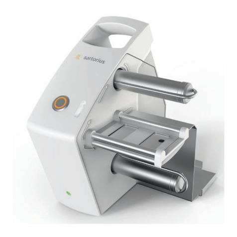
Sartorius Arium H2O-ARST-P-B User manual

Operating Instructions
Original Operating Instructions
Arium®Smart Station
H2O-ARST-P-B | H2O-ARST-P-T | H2O-ARST-UP-B|H2O-ARST-UP-T
Dispensing Unit
1000084125


Arium®Smart Station Operating Instructions 3
Contents
Contents
1 About these Instructions...........................5
1.1 Scope.......................................... 5
1.2 Accompanying Documents ................... 5
1.3 Target Groups ................................. 5
1.4 Symbols Used ..................................6
1.4.1 Warnings in Operation Descriptions ....6
1.4.2 Other Symbols . . . . . . . . . . . . . . . . . . . . . . . . . .6
2 Safety Information .................................7
2.1 Intended Use...................................7
2.1.1 Modifications to the Device.............7
2.1.2 Device Repairs and Maintenance .......7
2.1.3 Foreseeable Misuse.....................8
2.2 Personnel Qualification ........................8
2.3 Significance of these Instructions ..............8
2.4 Device Functionality............................8
2.5 Safety Information on the Device ..............9
2.6 Electrical Equipment ...........................9
2.6.1 Damage to the Device’s Electrical
Equipment ..............................9
2.6.2 Power Supply Unit and Power Supply
Cable....................................9
2.7 Accessories, Consumables, and Spare Parts....9
3 Device Description................................10
3.1 Device Overview ............................. 10
3.2 Hand-held Part................................11
3.3 Water Connections and Clips .................12
3.4 Electrical Connections ........................13
3.5 Models H2O-ARST-UP-B, H2O-ARST-P-B:
Wall Brackets for the Dispensing Unit.........14
3.6 Power Supply Unit and Wall Bracket ..........15
3.7 “Ultrapure” Version: Serial Connection of
Several Dispensing Units ......................16
3.7.1 System Setup ..........................16
3.8 Symbols on the Device ........................16
4 Operating Design ................................. 17
4.1 “Ultrapure” Version: Operating Elements in
Dispensing Mode..............................17
4.2 “Pure” Version: Operating Elements in
Dispensing Mode..............................18
4.3 Menu ..........................................19
4.3.1 “User” Role (Without PIN Protection) .19
4.3.2 “Administrator” Role ..................20
4.4 Messages in Dispensing Mode ................21
4.5 Message List .................................22
4.6 Numeric Keypad .............................23
4.7 Status Display of the Buttons.................23
4.8 Buttons in the Operating Display.............24
4.8.1 Buttons for Operation and Navigation
in Displays ............................24
4.8.2 Buttons for Editing or Managing
Entries ................................25
4.9 Navigating Menus ............................26
4.10 Menu Structure .............................. 27
4.11 Parameter List ................................28
4.11.1 Parameters in the “Information”
Menu..................................28
4.11.2 Parameters in the “Settings|
DisplayTemperature” Menu ..........29
4.11.3 Parameters in the “Settings|
Final Filter Reminder” Menu ..........29
4.11.4 Parameters in the “Settings|
Flow Rate” Menu......................29
4.11.5 Parameters in the “Settings|
Acoustic Signals” Menu...............30
4.11.6 Parameters in the “Settings|
Display Brightness” Menu.............30
4.11.7 Parameters in the “Settings|
Reset Settings” Menu.................30
4.11.8 Parameters in the “Role
Management” Menu...................31
4.11.9 Parameters in the “Care” Menu . . . . . . . .31
4.11.10 Adopting Parameters from theArium®
WaterTreatment Device ...............31
5 Installation ........................................32
5.1 Scope of Delivery.............................32
5.2 Selecting an Installation Site .................33
5.3 Unpacking and Installing the Device .........34
5.4 Installing the Stand Support Rod (Only for
Dispensing Unit with Stand)..................34
5.5 Installing the Stand Arm (Only for Dispensing
Unit with Stand) ..............................35
5.6 Installing the Wall Bracket for the Power
Supply Unit...................................36
5.6.1 Securing Wall Bracket with the
Adhesive Tapes .......................36
5.6.2
Securing the Wall Bracket with Screws
36
5.7 Dispensing Unit withWall Bracket:
Installing Wall Bracket for the Control Unit... 37
5.8 Dispensing Unit with Wall Bracket:
Securing Control Unit to the Wall Bracket ... 37
5.9 Dispensing Unit with Wall Bracket: Installing
the Wall Bracket for the Hand-held Part .....38
5.10 Acclimatization...............................38

4 Arium®Smart Station Operating Instructions
Contents
6 Getting Started ...................................39
6.1 Connecting Water Tubes .....................39
6.1.1 For “Ultrapure” Version: Establishing
Serial Water Circulation System for one
Dispensing Unit .......................39
6.1.2 For “Ultrapure” Version: Establishing
Serial Water Circulation System for up
to Three Dispensing Units.............40
6.1.3 For “Pure” Version: Connecting the Dis-
pensing Unit to the Arium®Bagtank ..43
6.1.4 For “Pure” Version: Connecting
Dispense Tube of the Hand-held Part
. 44
6.1.5 For “Ultrapure” Version: Connecting
Dispense Tubes of the Hand-held Part
. 44
6.1.6 LeakTest ..............................44
6.1.7 Connecting the Hand-held Part ......44
6.1.8 Installing the Hand-held Part .........45
6.1.9
Connecting the Ethernet System Cable
45
6.1.10 Inserting Clips.........................45
6.1.11 Securing Protective Tubing ...........46
6.2 Connecting the Power Supply Unit...........46
6.3 Connecting the Final Filter (Optional) .......48
7 Operation.........................................49
7.1 Switching the Device On and Off.............49
7.2 Dispensing Water.............................49
7.2.1 Preparing to Dispense Water .........49
7.2.2 Dispensing Water Manually ...........50
7.2.3 Dispensing Water with Volume-control 51
7.2.4 Confirming Dispensing Cancellation..54
7.3 Opening the Menu ...........................55
7.4 Activating or Deactivating Standby Mode....55
7.4.1 ECO Mode............................55
7.4.2 Standby Mode ........................55
7.5 Changing System Settings ...................56
8 Cleaning and Maintenance .......................57
8.1 Cleaning......................................57
8.1.1 Cleaning the Operating Display.......57
8.1.2 Cleaning the Device Housing.........57
8.2 Maintenance Schedule.......................58
8.3 Opening the “Care” Menu....................58
8.4 Changing the Final Filter .....................59
8.4.1 Removing the Final Filter .............59
8.4.2 Connecting the New Final Filter ......59
8.5 Performing Venting...........................60
8.6 “Pure” Version: Perform Depressurization . . . . .61
8.7 Enabling, Disabling, or Configuring Reminders
for Replacing Final Filters ....................62
9 Faults .............................................63
9.1 Warning Messages ...........................63
9.2 Error Messages ...............................63
9.3 Other Faults ..................................64
10 Decommissioning .................................65
10.1 Decommissioning ............................65
11 Transport..........................................65
11.1 Transporting the Device......................65
12 Storage and Shipping .............................66
12.1 Storage .......................................66
12.2 Returning the Device and Parts ..............66
13 Disposal...........................................67
13.1 Decontaminating the Device.................67
13.2 Disposing of Device and Parts................ 67
14 Technical Data ....................................68
14.1 Dimensions and Weights .....................68
14.1.1 Dispensing Unit with Stand ...........68
14.1.2 Dispensing Unit with Wall Bracket ....68
14.2 Installation Conditions .......................68
14.2.1 Space Requirement for the
Dispensing Unit with Stand ...........68
14.3 Ambient Conditions..........................69
14.4 Storage Conditions...........................69
14.5 Electrical Data................................69
14.5.1 Power Supply to the Power Supply
Unit ...................................69
14.5.2 Power Consumption of the
Dispensing Unit .......................70
14.5.3 Safety and Electrical Compatibility ...70
14.6 Device Functions.............................70
14.7 Interfaces......................................71
14.7.1 Specifications of the Ethernet
Interfaces ..............................71
14.7.2 Specifications for the USB-C
Interface ...............................71
14.8 Permitted Devices or Components............71
14.9 Materials ......................................71
14.10Cleaning Agents and Cleaning Procedures ...71
14.10.1 Cleaning Agents .......................71
14.10.2 Cleaning Procedure....................71
14.11 Information on Disposal . . . . . . . . . . . . . . . . . . . . . . 72
14.11.1 Batteries .............................. 72
14.12 IT Connection of the Device.................. 72
14.12.1 Using the IT Connection .............. 72
14.12.2 General Recommendations for
Access Restrictions ................... 72
15 Accessories and Consumables ....................73
15.1 Accessories................................... 73
15.2 Consumables................................. 73
16 Sartorius Service ..................................73
17 Conformity Documents ...........................73

About these Instructions
Arium®Smart Station Operating Instructions 5
1 About these Instructions
1.1 Scope
These instructions are part of the device. These instructions apply to the
device in the following versions:
Device Model
Dispensing unit as benchtop version for
ultrapure water, “Ultrapure” version (type 1)
H2O-ARST-UP-T
Dispensing unit as benchtop version for pure
water, “Pure” version (type 2 and type 3)
H2O-ARST-P-T
Dispensing unit with wall mounting bracket for
ultrapure water, “Ultrapure” version (type 1)
H2O-ARST-UP-B
Dispensing unit with wall mounting bracket for
pure water, “Pure” version (type 2 and type 3)
H2O-ARST-P-B
1.2 Accompanying Documents
t In addition to these instructions, observe the following documentation:
−Instructions for the water treatment device used, e.g. Arium®Pro,
Arium®Comfort, Arium®Advance, and Arium®Bagtank
1.3 Target Groups
The instructions are designed for the following target groups. The target
groups must possess the knowledge listed below.
Target Group Knowledge and Qualifications
User The user is familiarwith the operation of the device and
the associated work processes.The user understands
the hazards which may arise when working with the
device and knows how to prevent them. They have
been trained in the operation of the device.
Administrator The administrator is responsible for integrating the
device into the production process. The administrator
ensures the reliable functioning of the system and
device software. The administrator is trained in the
operation of the device.
Operator The operator of the device is responsible for ensuring
compliance with workplace health and safety
regulations.The operator must ensure that anyone
working with the device has access to the relevant
information and is trained to workwith the device.

About these Instructions
6 Arium®Smart Station Operating Instructions
1.4 Symbols Used
1.4.1 Warnings in Operation Descriptions
WARNING
Denotes a hazard that may result in death or severe injury if it is not avoided.
CAUTION
Denotes a dangerwith risk that moderate or minor injury may result if it is
not avoided.
NOTICE
Denotes a hazard that may result in property damage if it is not avoided.
1.4.2 Other Symbols
t Required action: Describes actions which must be carried out.
The actions in the sequence must be carried out in succession.
y Result: Describes the result of the actions carried out.
[ ] Text inside brackets refers to operating and display elements.
[ ] Text inside brackets indicates status, warning, and error
messages.
Figures on the Operating Display
The figures on the operating display of the device may differ from those in
these instructions.

Safety Information
Arium®Smart Station Operating Instructions 7
2 Safety Information
2.1 Intended Use
The device is a dispensing unit and is used to dispense water from an Arium®
water treatment device or Arium®Bagtank. The device must be operated
with pure or ultrapure water in a laboratory.
Up to three dispensing units can be connected to an Arium®water
treatment device in series.
The device is exclusively designed for use according to these instructions.
Any further use beyond this is considered improper.
If the device is used improperly:The device’s protective systems may be
impaired. This can lead to unforeseeable personal injury or property
damage.
Operating Conditions for the Device
Do not use the device in potentially explosive environments. Only use the
device indoors.
The device may only be used with the equipment and under the operating
conditions described in the Technical Data section of these instructions.
2.1.1 Modifications to the Device
If the device is modified, for example by attaching extra components: The
safety of the device may be impaired or the device compliance may lose its
validity.
If you have any queries regarding modifications to the device, contact
Sartorius.
2.1.2 Device Repairs and Maintenance
Device repairs and maintenance may only be carried out by persons with
appropriate specialized knowledge. If the device is not repaired or serviced
by a specialist:The safety of the device may be impaired or the test marks
may lose their validity.
We recommend that any repairwork, even that not covered by the warranty,
is carried out by Sartorius Service or after consulting Sartorius Service.
Only the maintenance tasks described in these instructions should be
carried out. For maintenance tasks that need to be carried out by Sartorius
Service, contact Sartorius Service.

Safety Information
8 Arium®Smart Station Operating Instructions
2.1.3 Foreseeable Misuse
It is only safe to use the device when operated in accordance with its
intended use.The following applications, for example, are not permitted:
−The vessel to be filled overflows due to unattended water dispensing.
−Do not use unfiltered water, instead only use pure or ultrapure water.
−Do not connect the device to a drinking water line.
−The connection of unsuitable devices.
2.2 Personnel Qualification
If individuals who do not have sufficient knowledge on the safe handling of
the device carry out work on the device: Those individuals may injure
themselves or other people nearby.
t Ensure that all persons working on the device possess the necessary
knowledge and qualifications (for description, see Chapter“1.3 Target
Groups”, page 5).
t If a particular qualification is required for the actions described: Have
these activities carried out by the required target group.
t If no particular qualification is required for the actions described: Have
these activities carried out by the “user” target group.
2.3 Significance of these Instructions
Failure to follow the instructions in this manual may have serious
consequences, e.g. danger to individuals.
t Read the instructions carefully and completely. The required actions in
the instructions build on each other.
t Ensure that the information contained in these instructions is available
to all individuals working on the device.
t Retain the instructions.
t If these instructions are lost, request a replacement or download the
latest version from the Sartorius website (www.sartorius.com).
2.4 Device Functionality
A damaged device orworn-out parts can cause malfunctions or lead to
hard-to-detect hazards.
t Only operate the device when it is safe and in proper working order.
t Complywith the maintenance intervals (for intervals and maintenance
work, see Chapter“8.2 Maintenance Schedule”, page 58).
t Organize the immediate repair of any malfunctions or damage by
Sartorius Service.

Safety Information
Arium®Smart Station Operating Instructions 9
2.5 Safety Information on the Device
Symbols, e.g., warnings and safety stickers, are safety information for
handling the device. Missing or illegible safety information may lead to
serious injuries.
t Do not conceal, remove, or modify the symbols.
t Replace the symbols if they become illegible.
2.6 Electrical Equipment
2.6.1 Damage to the Device’s Electrical Equipment
Damage to the device’s electrical equipment, e.g., damaged insulation, may
result in unforeseeable hazards.
t If the electrical equipment of the device is defective, cut off the power
supply and contact Sartorius Service.
t Keep live parts away from moisture. Moisture can cause short circuits.
2.6.2 Power Supply Unit and Power Supply Cable
Serious injury can result, e.g., from electric shocks, if an unsuitable/
inadequately dimensioned power supply cable or unsuitable power supply
unit is used.
t Only use the original power supply unit and original power supply cable.
t If the power supply unit or power supply cable must be replaced: Please
contact Sartorius Service. Do not repair or modify the power supply unit
or power supply cable.
2.7 Accessories, Consumables, and Spare Parts
Unsuitable accessories, consumables, and spare parts can adversely affect
functionality and safety, and have the following consequences:
−Risk of injury to persons
−Damage to the device
−Device malfunctions
−Failure of the device
t You should only use approved accessories, consumables, and spare parts
supplied by Sartorius.
t Only use accessories, consumables, and spare parts that are in proper
working order.

Device Description
10 Arium®Smart Station Operating Instructions
3 Device Description
3.1 Device Overview
5
8
9
3
1
6
4
2
7
Fig.1: Dispensing unit with stand (example)
Pos. Name Description
1 Hand-held Part Controls the dispensing of water.
2 Stand arm Holds the hand-held part.
3 Adjustment button Used to set the height for the hand-held part.
4 Protective tubing Used to protect the water tubes and the data cable.
5 Stand support rod Used for the height adjustment of the hand-held part.
6 Stand base Connects the control unit with the stand support rod.
7 Base plate
8 Control unit −Displays information about the system operation.
−Carries out system settings and work steps for the maintenance of the
device via a menu.
9 Operating display Has a touch-sensitive surface.

Device Description
Arium®Smart Station Operating Instructions 11
3.2 Hand-held Part
2
1
6
5
3
4
Fig.2: Hand-held part of the dispensing unit
Pos. Name Description
1 [Start / stop] button −If the key is briefly pressed: Starts or stops the dispensing.
−If the button is held down: Manual dispensing.
−If the button is released: Dispensing will be stopped.
2 [Plus] button −For “Ultrapure” version only: Starts the manual dispensing at level 1.
−For “Ultrapure” version only:When pressed, it increases the flow speed
by one level during volume-controlled dispensing.
−For “Ultrapure” version only:When held down, it increases the flow
speed level by level.
−Changes the menu selection for pre-defined levels of volume-
controlled dispensing.
3 Hand-held part Has an integrated touch sensor.
4 Water outlet Used for the connection of the final filter.
5 [Volume] button Starts the selection for the volume-controlled dispensing in pre-defined
levels.
6 [Minus] button −For “Ultrapure” version only:When pressed, it decreases the flow speed
by one level during volume-controlled dispensing.
−For “Ultrapure” version only:When held down, it decreases the flow
speed level by level.
−Changes the menu selection for pre-defined levels of volume-
controlled dispensing.

Device Description
12 Arium®Smart Station Operating Instructions
3.3 Water Connections and Clips
2
1
4
6
4
3
4
5
Fig.3: Water connections and clip (example)
Pos. Name Description
1 Mounting hole Clips are attached.
2 “Outlet” connection For “Ultrapure” version only: Used to connect the outlet tube to an Arium®
water treatment device or to the connection of anotherArium®Smart
Station.
3 “Inlet” connection −Used to connect the feed water tube and connects this device with an
Arium®water treatment device or Arium®Bagtank.
−For serial connection of several dispensing units: The feed water tube
connects the device with an upstreamArium®“Ultrapure” Smart
Station.
4 Clip Secures the protective tubing to the device.
5 “Red” hand-held part
connection
For “Ultrapure” version only: Used to connect the outlet tube from the
hand-held part.
6 “Blue” hand-held part
connection
For connecting the feed water tube to the hand-held part.

Device Description
Arium®Smart Station Operating Instructions 13
3.4 Electrical Connections
4
5
1 2 3
Fig.4: Electrical connections (example)
Pos. Name Description
1 Hand-held part connection Used to connect the hand-held part to the control unit.
2 Ethernet “A” Used to connect anArium®water treatment device or another Arium®
Smart Station.
3 Ethernet “B” Used to connect anArium®water treatment device or another Arium®
Smart Station.
4 USB-C Used to connect accessories, e.g., printers or USB mass storage devices
(for maximum storage size, see Chapter“14.7.2 Specifications for the
USB-C Interface”, page 71).
5 Power supply Used to connect the power supply unit.

Device Description
14 Arium®Smart Station Operating Instructions
3.5 Models H2O-ARST-UP-B, H2O-ARST-P-B: Wall Brackets for the
Dispensing Unit
2
3
4
1
4
Fig.5: Wall brackets for the dispensing unit (example)
Pos. Name Description
1 Wall bracket for hand-held part Used to hold the hand-held part.
2 Clip Secures the protective tubing.
3 Wall bracket for the control unit Used to hold the control unit.
4 Fixing screw Secures the control unit to the wall bracket.

Device Description
Arium®Smart Station Operating Instructions 15
3.6 Power Supply Unit and Wall Bracket
2
1
32
1
3
Fig.6: Power supply unit and wall bracket (example)
Pos. Name Description
1 Power supply unit Used to supply power to the device.
2 Power supply cable Has a country-specific plug type.
3 Wall bracket for power supply unit Secures the power supply unit horizontally or vertically to a wall.

Device Description
16 Arium®Smart Station Operating Instructions
3.7 “Ultrapure” Version: Serial Connection of Several Dispensing Units
3.7.1 System Setup
13
2
Fig.7: System setup with up to three dispensing units (example)
Pos. Name Description
1 Arium®water treatment device Supplies the ultrapure water to the dispensing units.
2 Protective tubing Contains the water tubes and the Ethernet system cable.
3 Dispensing unit Used for the removal and dispensing of ultrapure water.
3.8 Symbols on the Device
Symbol Meaning
Electrical voltage: Risk of injury due to live parts. Only electricians may have access to and work on
these parts.

Operating Design
Arium®Smart Station Operating Instructions 17
4 Operating Design
4.1 “Ultrapure” Version: Operating Elements in Dispensing Mode
In dispensing mode, the display shows information from the connected Arium®water treatment device, as well as the
buttons relevant for dispensing.
6
2
1
3
5
4
Fig.8: Dispensing mode of the dispensing unit for ultrapure water (schematic representation)
Pos. Name Description
1 Status bar −Indicates the water type, e.g., ultrapure.
−If there are messages present:
−Indicates that messages have been saved.
−Opens a message or the message list.
2 Measurement display Can display the following information:
−Current temperature (setting-dependent)
−Current conductivity
−Current TOC value (if available):
−Value shown in black: current measured value
−Value shown in gray: previous measured value
−Moving dots over the unit:The value is being updated
−Messages
3 Function bar Displays available operating functions for the current display.
4 Menu Opens the main menu.

Operating Design
18 Arium®Smart Station Operating Instructions
5 Flow speed −Indicates the level of the current flow speed using the number of
colored droplets.
−[-] and [+] symbols: Indicate that the flow speed can be increased or
reduced using the [Plus] and [Minus] buttons on the hand-held part.
−[+] and [–] symbols light gray or not visible: Indicates that the flow
speed cannot be changed.
6 Flow symbol Indicates whether water is currently being released.
4.2 “Pure” Version: Operating Elements in Dispensing Mode
In dispensing mode, the display shows information from the connected Arium®water treatment device, as well as the
buttons relevant for dispensing.
5
2
1
3
4
Fig.9: Dispensing Mode of the Dispensing Unit for PureWater (Schematic Representation)
Pos. Name Description
1 Status bar −Indicates the “Pure” water type.
−If there are messages present:
−Indicates that messages have been saved.
−Opens the message list.
2 Measurement display Can display the following information:
−Current conductivity
−Current temperature (setting-dependent)
−Messages
−Values shown in gray are not current measured values, but values
obtained during the last water production.
3 Function bar Displays available operating functions for the current display.
4 Menu Opens the main menu.
5 Bagtank display Displays the tank capacity and the filling level of the Arium® Bagtank.

Operating Design
Arium®Smart Station Operating Instructions 19
4.3 Menu
4.3.1 “User” Role (Without PIN Protection)
All system settings and work steps for dispensing can be carried out in the
menu.
5
Dispensing
13
4
Care
2
Fig.10: Menu for the “User” role (example)
Pos. Symbol Name Description
1Dispensing Opens the dispensing mode.
2Care Opens the “Care” menu.
3 Identifier If more than one dispensing unit is
connected: Displays the name and the
ID number.
4 Log in role Changes the role from “User” to
“Administrator” or “Service”.
5 Function bar Displays available operating functions
for the current display.

Operating Design
20 Arium®Smart Station Operating Instructions
4.3.2 “Administrator” Role
All system settings and work steps for the maintenance of the device can be
carried out in the menu.
6
41
5
2 3
Dispensing Care
Administrator Arium Smart Station 1
Fig.11: Menu for the “Administrator” role (example)
Pos. Symbol Name Description
1Dispensing Opens the dispensing mode.
2 User role If available: Displays the name of the
active user profile.
3Care Opens the “Care” menu.
4 Identifier If more than one dispensing unit is
connected: Displays the name and the
ID number.
5Log out a
role
Logs out the currently logged-in
Administrator or Service.
Returns to the “User” role.
6 Function bar Displays available operating functions
for the current display.
This manual suits for next models
3
Table of contents
Other Sartorius Dispenser manuals