Sartorius Sartocheck 3 plus User manual

Operating Instructions | Betriebsanleitung
Sartocheck® 3 plus
Filter Integrity Tester | Filterintegritäts-Testgerät
Version 1.00
1000025367

Contents
English . . . . . . . . . . . . . . . . . . . . . . . . . . . . . 3
Inhalt
Deutsch ........................... 56
Translation
When the unit is supplied to countries in
the EEA, the operating instructions must be
translated into the language or languages of
the country of use. If any discrepancies arise
in the translated text, the original German
operating instructions shall form the basis
for clearer interpretation or the manufacturer
must be contacted.
Copyright
Reproduction, dissemination, transfer by any
means and other use is not permitted without
the prior written consent of Sartorius Stedim
Biotech GmbH. Offenders will be liable for
damages. All rights reserved.

3
1.1 Table of Contents
1 Contents ..................... 3
1.1 Table of contents .............. 3
1.2 FCC ......................... 5
2 Overview and Proper Use ........ 6
2.1 Overview . . . . . . . . . . . . . . . . . . . . . 6
2.2 Proper Use .................... 6
2.3 Technical Data ................ 7
2.3.1 Dimensions and Weight ......... 7
2.3.2 Connection Data ............... 7
2.3.3 Pneumatics ................... 7
2.3.4 Test Media ................... 7
2.3.5 Product-Specific Data ........... 8
2.3.6 Test Methods ................. 8
2.3.7 General Data .................. 8
3 Safety ....................... 9
3.1 Notes|Explanations ............. 9
3.1.1 Device Identification ............ 9
3.2 Integrated Safety Devices ....... 10
3.3 Safety Measures .............. 10
(to be Performed by the Operator)
3.4 Obligations of the Operator ...... 10
3.5 Safety Tests Performed by the
Manufacturer at the Factory ...... 10
4 General Warnings ............ 11
4.1 Hazards .................... 11
4.2 Operating and
Maintenance Personnel ......... 11
4.3 Inserting Replacement
and Wearing Parts ............. 11
4.4 Switch-Off Procedures ......... 11
5 Installation ................. 12
5.1 Delivery Scope ............... 12
5.2 Goods Acceptance . . . . . . . . . . . . . 12
5.3 Setup Instructions ............. 13
5.3.1 Environmental and Site Conditions . 13
5.3.2 Transport and Unpacking ....... 13
5.4 Connections ................. 13
5.4.1 Front Side and Back Side ........ 13
5.4.2 Left and Right Sides of the Device . 14
5.4.3 SD Card Reader Description ...... 14
5.5 Connections with Internal
Pressure Sensor ............... 15
5.6 Replacing the Paper Roll and the
Ink Ribbon ................... 16
1 Contents
6 Functionality ................ 17
6.1 General Functional Description. . . . 17
6.2 Test Programs ................ 17
6.3 Management of the Test Results . . 17
6.4 Functionality Test ............. 17
6.5 Cleaning .................... 17
6.6 Self-Test for Broken Conductors
and Short-Circuiting ........... 18
6.7 Calibration .................. 18
6.8 Internal Pressure Sensor ........ 18
6.9 Pressure Gauge Function ........ 18
6.10 Cleaning|Drying .............. 18
6.11 Safety Functions .............. 18
6.12 Software Update .............. 18
6.13 Serial Number ................ 18
7 Operation ..................19
7.1 Switching on the Device ........ 19
7.1.1 Operating Elements . . . . . . . . . . . . 20
7.2 Switching the Device ON and OFF . 21
7.2.1 Test Execution ................ 22
7.2.2 Switching Off the Device ........ 22
7.2.3 Switching off the Device on
the Failure of the Power Supply ... 22
7.3 Tests ...................... 22
7.3.1 Test Conditions ............... 22
7.3.2 Test Selection ................ 22
7.3.3 Programming the Test ......... 23
7.4 Diffusion Test ................ 23
7.5 Bubble Point Test ............. 27
7.6 Diffusion and Bubble Point Test
(Complete Test) .............. 28
7.7 Water Intrusion Test|
Water Flow Test .............. 28
7.8 Pressure Drop Test ............ 29
7.9 Multidiffusion Test ............ 29
7.10 Volume Measurement .......... 30
7.11 Customer-Specific BP. . . . . . . . . . . 30
7.12 Customer-Specific Multidiffusion . 30
7.13 Program Database ............. 31
7.13.1 Test Program From
Internal Memory
(F1 - program database) ......... 31
7.13.2 Reading in the Test Program
from the SD Card
(F2 - Program Database) ........ 32
7.13.3 Saving a Backup of All Test
Programs on SD Card ........... 33
7.13.4 Reading in the Backup of All
Test Programs from the SD
Card (F6 - Program Database) .... 34
7.14 Visualization ................. 35

4
7.15 Special Functions ............. 35
7.15.1 Function Test of
Management Unit ............ 35
7.15.2 Function Test of Test Unit ...... 35
7.15.3 Cleaning ................... 36
7.15.4 Drying ..................... 37
7.15.5 Pressure Gauge Function ....... 37
7.15.6 Changing Your Own Password ... 37
7.16 Service .................... 38
7.16.1
Hardware Configuration ..........38
7.16.1.1 Interfaces and External Connections . 38
7.16.2 Software Configuration ..........39
7.16.3 Calibration|Alignment .......... 42
7.16.3.1 Calibration and Alignment of the
Internal Pressure Sensor ........ 43
7.16.4.2 Managing Users .............. 45
8 Maintenance|Servicing ....... 46
8.1 Maintenance ................ 46
8.1.1 Replacing the Microfuses ....... 46
8.1.2 Sartorius Stedim Biotech
Service Menu ................ 46
8.2 Cleaning ................... 46
9 Troubleshooting .............. 47
9.1 Troubleshooting .............. 47
10 Emergencies ................ 49
11 Information and Instructions
on Disposal and Repairs ....... 49
12 Annex ..................... 50
12.1 Detailed Test Description ....... 50
12.1.1 Diffusion Test ................ 50
12.1.2 Bubble Point Test ............. 50
12.1.3 Pressure Drop Test ............ 51
12.1.4 Water Intrusion Test|
Water Flow Test .............. 51
13 Index ...................... 53

5
Shielded Cables
Connections between the devices
and peripherials must be made
using shielded cables in order to
maintain compliance with FCC
radio frequency emission limits.
Modifications
Any modifications made to this
device that are not approved by
Sartorius Stedim Biotech GmbH
may void the authority granted
to the user by the FCC to operate
this equipment.
1.2 FCC
Note:
This equipment has been tested
and found to comply with the
limits for a Class B digital device,
pursuant to part 15 of the FCC
Rules. These limits are designed
to provide reasonable protection
against harmful interference in
a residential installation. This
equipment generates, uses and
can radiate radio frequency energy
and, if not installed and used in
accordance with the instructions,
may cause harmful interference to
radio communications. However,
there is no guarantee that interfer-
ence will not occur in a particular
installation. If this equipment
does cause harmful interference to
radio or television reception, which
can be determined by turning the
equipment off and on, the user is
encouraged to try to correct the
interference by one or more of the
following measures:
– Reorient or relocate the receiving
antenna.
– Increase the separation between
the equipment and receiver.
– Connect the equipment into
an outlet on a circuit different
from that to which the receiver
is connected.
– Consult the dealer or an experi-
enced radio|TV technician for help.

2.2 Proper Use
The Sartocheck® 3 plus is a filter
integrity tester. It was exclusively
developed, constructed and built
for the industrial and commercial
purpose of conducting filter tests
in pharmaceutical and biotechno-
logical production and laboratory
operations.
The unit is not intended for use in
or with explosive atmospheres!
The system is exclusively designed
for the purpose defined above.
Any other application above or
beyond this or any modifications
to the unit without the written
permission of the manufacturer
is not considered proper use.
Sartorius Stedim Biotech GmbH
cannot assume liability if
Sartocheck® 3 plus integrity test
units are subjected to improper use
or
improper operation. Sartorius
Stedim
Biotech is not liable
for
any damages resulting therefrom.
The operator bears the sole risk.
Proper use also includes compli-
ance with operating, inspection and
maintenance conditions prescribed
by the manufacturer. Non-com-
pliance with the warnings in the
operating instructions and instal-
lation instructions, in particular,
constitutes improper use of the
equipment. Only EMC-tested con-
trol leads and accessories may be
used. Units may only be returned in
their original boxes or appropriate
secure packaging. No liability can
be accepted for transport damage.
6
2 Overview and Proper Use
2.1 Overview: Sartocheck® 3 plus
Fig. 2-1 | Overview
Device figure
1 printer
2 display
3 keypad
4 Status LEDs
!
1
2
3
4

7
2.3 Technical Data
2.3.1 Dimensions and Weight
Sartocheck® 3 plus
Length: 460 mm
Width: 390 mm
Height: 212 mm
Weight: 13 kg
Packing Weight: 2.7 kg
2.3.2 Connection Data
Sartocheck® 3 plus
Power requirements
Operating voltage: 100-240 V/±10%
Number of phases: 1 Ph/N
Neutral conductor: Loadable N (in the Appendix)
Grounding conductor: Separate SL (yellow-green) (in the Appendix)
Frequency: 47-63 Hz
Protection rating: IP 44
Installation: According to VDE regulations
Allowable voltage fluctuation: ± 10% from normal value
Maximum operating pressure: 10 bar g
Operating pressure: min. 4 bar g
Maximum power input: 74 Watt
Internal limit pressure: 10 bar g
2.3.3 Pneumatics
Sartocheck® 3 plus
Required compressed air 4–9 bar g
Water, oil and particle free
2.3.4 Test Media
Sartocheck® 3 plus
Test gas: Compressed air, dehydrated and deoiled
Wetting fluid: Water or as described with the process
validation documents for the filter cartridge
to be tested

2.3.5 Product-Specific Data
Manual input range
upstream system volume 0*1)
–100000 ml
*1) When 0 is input, the upstream
system volume is measured.
Measuring Ranges
– Test pressure: 100–8000 mbar
– Pressure drop: 1–2000 mbar
– Max. measur-
able volume: 100000 ml
– Diffusion: 0.1–999.9 ml/min
– Water
intrusion: 0.1–999 ml/10 min
– Water flow: 0.01–99.9 ml/min
– Bubble point: 100–8000 mbar
Measuring Accuracy
– Pressure ± 0.1% ± 9.5 mbar
– Pressure drop ± 1 mbar
– Net volume
measurement ± 4 %
– Diffusion ± 5%
– Water
intrusion ± 5%
– Bubble point ± 50 mbar
Operating Conditions
– Room
temperature +15°C to +35°C
– Rel. humidity 10-80%
Display
– Size 8.4"
– Resolution 640 + 480 pixels
Data Output
– Service TU RS232 | RS485
– Service MU RS232
8
2.3.6 Test Methods
Test method Without ext. ref. tank With ext. ref. tank
Press. drop test: All filter systems up to net volume of 100 l
Diffusion test: Cartridge systems up to Cartridge systems up
net volume of 9000 ml net volume of 100000 ml
Bubble point test: Small systems and cartridge Small systems and cartridge
systems up to net volume systems up to net volume
of 9000 ml of 50000 ml
Multipoint diffusion Cartridge systems up to –
test: net volume of 9000 ml
Diffusion and Cartridge systems up to Cartridge systems up to
bubble point test net volume of 9000 ml net volume of 50000 ml
(complete test)
Intrusion test, Cartridge systems up to –
water flow test net volume of 9000 ml
2.3.7 General Data
Ambient conditions
Ambient
temperature: +5 up to
+35°C
Noise level: < 70 dB
Humidity: 95% at 25°C
The stated values apply from sea
level up to 2000 m.
The unit should be set up under
ambient conditions that produce
no negative effects during opera-
tion and processing, e.g. from
contaminated airflows, metallic
dust or fluids from leaks, conden-
sation, aerosols or widely changing
temperature conditions.
!

3.1 Notes|Explanations
Operating instructions
are binding;
the symbol is framed and
designated by a “book”.
Warnings
are framed and designated by
a “Hazard” triangle.
Electrical Hazards
are framed and designated by
the symbol to the left.
Notes
are framed and designated
by a “Hand”.
Grounding Conductor Connection
Is designated by this symbol at the
connection sites.
Mandatory Instructions
For handling electrical plug
connections.
9
3 Safety
The information contained in these
operating instructions applies to the
Sartocheck® 3 plus, item no. 16290.
The manufacturer’s label is affixed
to the rear panel of the unit.
Important:
if you have any questions
Always have the following
information ready:
– Model
– Version
– Serial number
Having the right information
readily available will ensure correct
and quick processing.
!
Fig. 3-1 | Device identification Sartocheck® 3 plus
3.1.1 Device Identification

10
3.2 Integrated Safety Devices
The installed safety equipment
must be inspected at regular test
intervals (d = daily, w = weekly,
m = monthly). The test methods
used are: S = sight inspection,
F = functional testing.
The unit has the following safety
equipment installed:
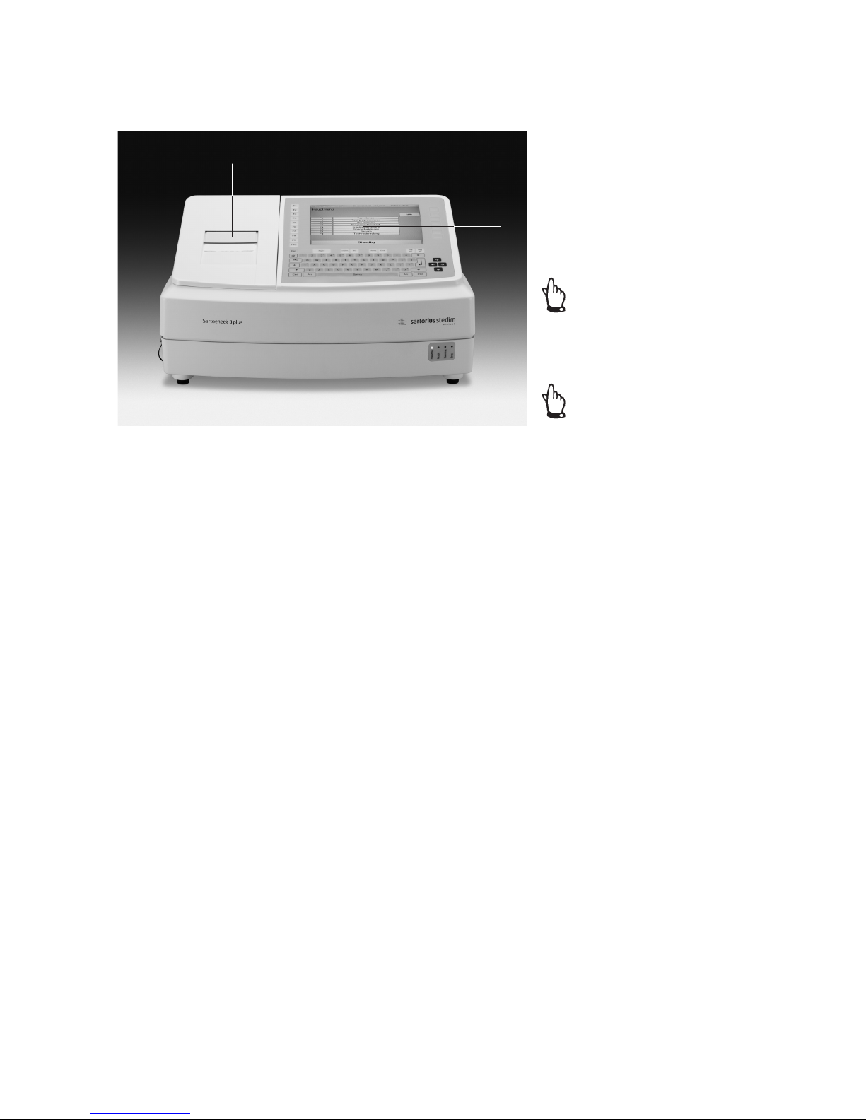
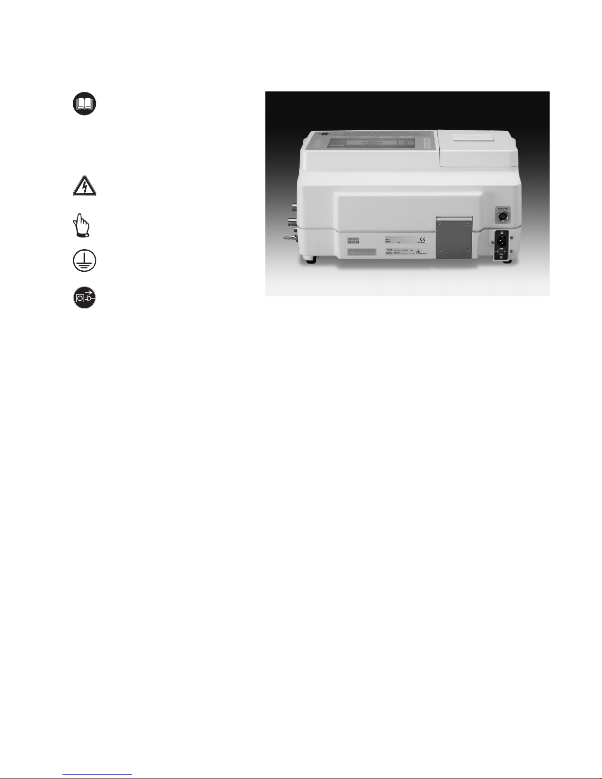
Line Disconnector
The unit is disconnected from the
mains voltage by switching off the
unit or when the unit is unplugged
from the wall outlet (mains supply).
Housing
All unit-specific components are
shielded against external influences
by a plastic housing. It is strictly
forbidden to disengage or disman-
tle the safety equipment. The func-
tion of this safety equipment must
be inspected and tested according
to the instructions given in the
Chapter “Maintenance”.
The operator is responsible for
instructing the operating personnel
and service and maintenance per-
sonnel about the meaning and the
function of the safety equipment.
These operating instructions are an
integral part of the unit and must
be available to operating personnel
and service and maintenance
personnel at all times.
The safety precautions and
warnings contained herein must
be observed.
3.3 Safety Measures
(to be performed by the operator)
The operator must
– Instruct his operating and servicing
personnel in the use of the filter
cartridge housing’s safety devices
and
– Ensure that the safety precautions
are complied with.
– The customer must prevent unau-
thorized persons (not operating and
servicing personnel) from access to
the filter cartridge housing danger
zone.
These operating instructions
must be kept in a safe place for
future reference. The frequency
of inspections and checks must
be observed.
The work described in these operat-
ing instructions is explained in such
a way that it can be understood
by trained workers and qualified
technicians.
Definitions Adapted from
EN 60204-1:
Trained Worker
A person familiarized with and, if
applicable, trained in his particular
duties by a qualified technician
and instructed about the potential
dangers in the event of improper
conduct and on the necessary safety
devices and safety precautions.
Qualified Technician
A person who, by virtue of his
technical training, know-how,
experience and knowledge of
relevant standards, is able to
assess the work assigned to him
and identify potential dangers.
3.4 Obligations of the Operator
In the European Economic Area
(EEA), the laws transposing Council
Directive (89/391/EEC) as well
as the corresponding individual
Directives and specifically includ-
ing Council Directive (89/655/EEC)
concerning the minimum safety and
health requirements for the
use of work equipment by workers
at work into national law in their
respectively valid versions must be
observed and compiled with.
In Germany, the Operational Safety
Regulation dated October 2002
must be observed (regulation
transposing the above-mentioned
Directives into national law).
The operator must obtain a local
operating permit and follow the
regulations and restrictions set
forth therein.
Additionally, the operator must
comply with the local rules and
regulations for:
– The safety of the personnel
(accident prevention regulations)
– The safety of the work equipment
(protective gear and equipment and
maintenance)
– Product disposal
(Waste Management Act)
– Material disposal
(Waste Management Act)
– Cleaning
(cleaning agents and disposal)
and the environmental rules and
regulations.
3.5 Safety Tests Performed by the
Manufacturer at the Factory
Testing and inspection according
to DIN EN 61010-1
!
Test
Interval Method
m S
Test
Interval Method
m S/F

11
4 General Warnings
4.1 Hazards
The safety systems and safety
notes described in these operating
instructions should be complied
with accordingly.
Keep the work area of the filter
cartridge housing free of objects
during operation so that unimpeded
access is possible at all times.
Before any installation, servicing
or repair work is carried out, make
sure you are aware of the electrical
hazards!
Unplug the equipment from the
wall outlet (mains supply) before
opening it!
Observe the required operating con-
ditions, especially with regard
to the temperature of the medium.
It is transmitted to the components.
Touching components or contact
with the medium can result in
burns or scalding.
Wear suitable protective clothing
if necessary. Don’t forget that the
components of the filter cartridge
housing store heat and cool down
slowly.
4.2 Operating and Maintenance
Personnel
Operating personnel and service
and maintenance personnel are
persons who are responsible for the
transport, installation, operation,
equipping, maintenance and clean-
ing as well as troubleshooting on
the unit.
1. The unit may only be operated
by trained and authorized per-
sons in accordance with operating
instructions that have been issued
by the operator.
2. The responsibilities for operation
of the unit must be clearly set
down and observed so that no
ambiguities arise with respect
to safety.
3. The safety precautions and
warnings given in the operating
instructions must be complied
with when carrying out any work
(operation, maintenance, repairs
etc.).
4. The operator shall never work in
any way that could impair the
safety of the unit or him|herself
or others.
5. It is the responsibility of the
operator to ensure that only
authorized persons work on
the unit.
6. It is the responsibility of the
operator to report immediately any
changes occurring on or to the unit
to the operating company.
7. It is the responsibility of the
operator to ensure that the unit is
only operated in perfect working
condition.
4.3 Inserting Replacement and
Wearing Parts
We must expressly draw your atten-
tion to the fact that replacement
parts and accessories that not have
been supplied by Sartorius Stedim
Biotech GmbH have not been tested
and approved by Sartorius Stedim
Biotech GmbH. The installation of
and|or the use of such products
can therefore have a negative effect
on the design properties of the unit
as constructed.
Sartorius Stedim Biotech GmbH is
not liable for any damages resulting
from the use of non-original parts
or non-original accessory parts.
Standard parts can be purchased
from specialized dealers.
4.4 Switch-off Procedures
The following shutdown procedure
must be followed before any
cleaning, servicing or repair work
is carried out.
1. Line disconnect
Turn off the main switch by pulling
out the AC adapter of the mains
supply.
2. Compressed air supply
Turn off the compressed air supply
and vent system.
Personnel may suffer physical inju-
ries or fatalities if this procedure is
not followed!
!

12
5 Installation
5.1 Delivery Scope
5.2 Goods Acceptance
Incoming inspection:
– Check the shipment for damage!
– Check the shipment against the
delivery note to ensure that it is
complete!
Complaints
If the shipment was damaged
during transit:
– Immediately contact the carrier!
– Keep the packaging material (in
case the carrier wants to inspect it
or the shipment has to be returned
to us)
If the shipment is not complete:
– Immediately contact Sartorius
Stedim Biotech GmbH or the
Customer Service Department in
your country!
If the delivery has other defects:
– Immediately contact Sartorius
Stedim Biotech GmbH or the
Customer Service Department in
your country!
The following are included in
the delivery scope of the Sarto-
check® 3 plus:
1. Filter integrity tester
Sartocheck® 3 plus, item no. 16290
2. Operating instructions and
technical documents
3. Accessories (not shown in
the picture)
– Tubing “Inlet” with compressed
air filter (I.D. = 6 mm)
Order no.: 18104
– Tubing “Outlet”
(I.D. = 4 mm) Order no.: 18103
– Spare ink ribbon cartridge
Order no.: 6982141
– Spare roll of printer paper
Order no.: 6982142
– Country-specific power cord
Packaging for Return Shipment
Use the original packaging and
original packaging material as far
as possible.
If the original packaging and
original packaging material are
no longer available:
– Commission a packaging company
with specialized technicians.
– Pack the unit in a shipping
container in such a way that
mechanical damage is prevented.
If you have any questions about
packaging and transport securing
devices, please contact Sartorius
Stedim Biotech GmbH.
Check the equipment supplied
against the delivery note.
Please report incomplete deliveries
immediately to the shipping carrier
or the supplier.
Interim Storage
The external packaging of the unit
and its spare and replacement parts
is designed for a storage period of
three months from delivery.
Units kept in interim storage must
be stored in a closed, dry room at
temperatures from +5°C to max.
+50°C.
Fig. 5-1 | Sartocheck® 3 plus
12

13
5.3 Setup Instructions
5.3.1 Environmental and Site Conditions
Select a place of installation that
meets the following conditions:
– no significant heat irradiation from
heating or sunlight
– no strong airflows
– no chemically aggressive
environment
– no significant shocks
– no dust impingement
– no significant impingement of
humidity
5.3.2 Transport and Unpacking
The unit and its accessories are
packaged according to the national
custom and protected against
impacts. To avoid damaging the
equipment, please comply with the
following notes and instructions:
– Please observe the Technical Data
in Chap. 3.
– Please observe the weight.
For transport to the unpacking site,
use a floor truck if appropriate.
– To prevent the unit from slipping,
it should always be carried or lifted
by two people.
– To open the packaging, remove the
unit and place it on a workbench
or table intended for that purpose.
– The workbench or table must be
level and able to bear the appro-
priate load. Allow sufficient space
around the workbench or table
for the operator to work.
– Unpack the accessories and
technical documents and put them
in a safe place.
– Moisture in the air can condense
on the surfaces of a cold unit
whenever it is brought into a
substantially warmer place. If
you transfer the unit to a warmer
area, make sure to condition it for
about 2 hours at room temperature,
leaving it plugged into AC power.
The positive temperature differ-
ential between the inside of the
unit and the ambient environment
essentially protects the unit against
humidity and moisture.
Open the packaging carefully. It is
a good idea to save the packaging
material (in case the carrier wants
to inspect it or the shipment has
to be returned).
Dispose of packaging materials
in compliance with prevailing
environmental safety regulations.
5.4 Connections
Before starting up the unit; make
sure that the unit is stable and
secure. Check all pneumatic and
electrical connections on the unit.
5.4.1 Front Side and Back Side
Fig. 5-2 | Front Panel
The following displays are located
on the front panel:
1 Standby
Is lit up when Sartocheck® 3 plus is
ready for operations, but not cur-
rently running any test program.
(Blinking LED)
2 Ready
Lights up when the result of the
filter test is ready. (LED lit)
3 Running
Is lit up when a test is currently
running. (LED lit)
4 Error
Lights up when the test unit has
identified an error and cancelled the
filter integrity test. (LED lit)
Fig. 5-3 | Back Panel
The following connection ports
are located on the back panel:
1 Housing ventilator
In the device, there is a ventilator
which ensures a constant tempera-
ture in the Sartocheck® 3 plus.
2 Service MU
Only Service function
(software upgrades)
3 AC adapter
Power plug for connecting the
power cord to mains supply.
4 Fuses
Fine-wire fuses between unit
and mains supply.
1 2 3 4 1 4
3
2

Fig. 5-4 | Left panel
Located on the left panel:
1 Main power switch
Switch on the power with the
main power switch.
2 Service TU
Only Service function
(software upgrades)
Fig. 5-5 | Right panel
Located on the right panel:
1 Ext. reference tank
Quick-release fastener for external
reference tank.
2 Venting 1
Outlet for ventilation 1
3 OUT
Quick-release fastener for test tube
4 Venting 2
Outlet for ventilation 2
5 IN
Quick-release fastener for
compressed air supply
14
5.4.3 SD card reader description
Fig. 5-6
1 SD card reader
2 cover
3 paper roll
1 2 3 4 5
1 2
123
Underneath the printer cover, there
is an SD card reader which can be
used for saving the test programs.
To prevent contamination, the
cover should be moved over the
opening (dust protection).
Do not remove the SD-Card during
the process of reading or writing.
5.4.2 Left and Right Device Sides of the Sartocheck® 3 plus

15
5.5 Connections With Internal
Pressure Sensor
The Sartocheck® 3 plus can be
operated with an internal pressure
sensor and with various tube con-
nections. The tube connections for
the Sartocheck® 3 plus are shown in
Fig. 5-7 and Fig. 5-8.
Attention!
Do not connect Sartocheck® 3 plus
to pressurized or high temperature
systems! Wait until the whole
system is at room pressure and
temperature!
Inlet Pressure During Operation
with Internal Pressure Sensor
The minimum operating pressure
required depends on the test meth-
od selected, but should be
at least:
> 4000 mbar and > 500 mbar
above the test pressure or above
the max. B.P. entered.
Check to make sure that all inlet
and outlet pressure tubing is con-
nected properly, that all electrical
connections have been correctly
installed, and that the paper roll
as well as the ribbon cartridge
have been inserted.
Fig. 5-7 | Connection with internal pressure sensor
Fig. 5-8 | Connection with internal pressure sensor and external vent
Sartocheck® 3 plus
Sartocheck® 3 plus

16
5.6 Replacing the Paper Roll and
the Ink Ribbon
To replace the paper roll, first
remove the printer cover by pushing
it backwards on the device. After
the cover has moved out of the
locking mechanism, it can easily be
removed by lifting it upwards.
Push the spindle into the hole in
the paper roll and insert the roll in
such a way that the spindle lies in
the holding device provided. The
paper must be fed on the lower
side backwards towards the print
unit. Feed the start of the paper
strip from the front directly into the
opening of the printer and briefly
press the "Paper" key. The paper
now feeds automatically through
the printer, along the ink ribbon,
and re-emerges from the top of the
print unit.
Now feed the printer paper from
the back|below through the slot in
the printer cover to its upper side so
that the paper re-emerges from the
device under the transparent cover.
Now replace the printer cover
on the device by feeding it from
above|behind onto the device and
pushing it from the back towards
the front until the cover slides into
the locking mechanism provided.
To replace the ink cartridge, the
printer cover must also be removed.
Afterwards, the black unit with
the ink ribbon can be removed by
pulling it upwards on its right side
(label "Lift"). The new ink cartridge
can then be reinserted in the oppo-
site sequence and the printer cover
can be closed again.
Make sure that the spindle of the
paper roll is correctly positioned in
the holding device provided.
Otherwise, the paper roll may jam
during the printing operation.

17
Sartocheck® 3 plus
1. printer
2. display
3. keypad
4. LED status lights
Fig. 6-1 | Overview
6 Functionality
6.1 General Functional Description
The Sartocheck® 3 plus is a
qualifiable filter integrity tester and
consists of a management unit and
a test unit.
The test unit is a mechanically,
pneumatically and electrically
closed functional unit.
A test unit cannot be operated
directly by the user, but is 100%
controlled by the data management
unit via an internal RS 485 inter-
face. With the help of its electrical
and pneumatic peripheral devices
the data management unit performs
the actual filter tests along with a
series of other additional functions.
Filter Integrity Test
The main purpose of Sartocheck® 3
plus is to test the integrity of mem-
brane filters according to various
methods.
6.2 Test Programs
In the test program, the procedural
steps and the parameters are set
down for the filter integrity test.
A programmed test program can
be loaded into the test unit and
the test will be run independently.
– Loading a test program
– Run a test program
The test unit runs through the
previously loaded test program, in
other words, it carries out the filter
integrity test and saves the result
in non-volatile memory. The data
management unit monitors the
progress of the filter test, i.e. it
reads in the current data in order
to present them to the user.
6.3 Management of the Test Results
In the management unit of the
Sartocheck® 3 plus, the measured
raw date (the test results) are pro-
cessed further, i.e. the units are
recalculated and the numbers are
converted into text.
6.4 Functionality Test
With the function test, the user
is able to interactively test the func-
tionality of pneumatic
components. The proportional
valves are not explicitly, but
rather implicitly tested in this
context.
6.5 Cleaning
Sartocheck® 3 plus starts the
procedure for cleaning and flushing
the internal lines and the volume
reference tank.
1
2
3
4

18
6.13 Serial Number
Every unit bears its own unique
serial number. The serial number
may not be changed during a
software update.
– The serial number is entered for
the first time during production
of the unit.
– If the PCB has to be replaced
during repairs that may arise later,
the unit must be assigned the
exact same serial number that is
imprinted on the manufacturer’s
label.
6.6 Self-Test for Broken Conductors
and Short-Circuiting
While controlling the valves and
sensors, the Sartocheck® 3 plus
hardware can check whether there
are any broken conductors or
short-circuits.
6.7 Calibration
The calibration function is used
to calibrate the internal pressure
sensor with the aid of more precise
reference measuring devices and to
adjust it if necessary. Each sensor
runs its own calibration date.
An adjustment routine automati-
cally follows the test. The test can
also be activated separately.
Sartocheck® 3 plus saves the raw
data for the calibration record in
permanent memory.
The operator can use the following
sensor types for determining the
reference pressure:
– Absolute pressure sensor:
The reference pressures are meas-
ured directly.
– Relative pressure sensor:
The measured reference pressures
relate to the ambient pressure. The
ambient pressure must be known or
measured with additional reference
measuring equipment.
6.8 Internal Pressure Sensor
Sartocheck® 3 plus sets either 6 or 8
pressure values and compares them
with the internal pressure sensor
and the pressure values measured
on the reference measuring instru-
ment (connected to the “OUT”
connector) to calculate scale and
linearization.
6.9 Pressure Gauge Function
In the pressure gauge function,
the Sartocheck® 3 plus behaves
like a digital pressure measuring
device. To do so, it uses the internal
pressure sensor.
6.10 Cleaning|Drying
Through the pneumatic connec-
tors, Sartocheck® 3 plus is able to
flush almost all internal volumes.
The user is responsible for ensuring
that no damage occurs to any com-
ponents of the Sartocheck® 3 plus
due to the pressure built up by the
pump used in the cleaning.
6.11 Safety Functions
– As one of its technical options,
Sartocheck® 3 plus runs the test
step Initialization|Security Status in
the event of a power failure. Basi-
cally, what this step does is close
the compressed air supply and the
block valve to the filter housing.
– Sartocheck® 3 plus is not responsi-
ble for ensuring whether the maxi-
mum pressure for the compressed
air supply to the filter housing is
too high. That means the user must
make sure that the initial pressure
cannot damage the filter housing.
6.12 Software Update
The operating software on
Sartocheck® 3 plus is updated
with a corresponding program run
exclusively with an external Laptop
(via the jacks Service MU| Service
TU). Since the configuration data
are localized in a battery-backed
RAM, they remain unchanged
during any software update.

19
7 Operation
Picture of Sartocheck® 3 Plus
1 printer
2 display
3 keypad
4 status lights
Fig. 7-1 | Overview
7.1 Switching on the device
1
2
3
4

General operating concept
The Sartocheck® 3 plus can be
operated using the keypad and the
various function keys. In general,
the menu is structured so that
the respective menu items can be
selected using the function keys to
the left and right next to the dis-
play. Alphanumeric entries can be
made via the keypad. Menu items
for which the alternative contents
have already been set (e.g. Yes or
No) can be changed by pressing
the associated function keys several
times.
The Sartocheck® 3 plus has an inter-
nal memory to store user-specific
settings and programmings (e.g.
test programs). There is no electro-
nic results database. Only the last
test result is retained in the memo-
ry, so that it can be printed out
again if necessary. This means that
the Sartocheck® 3 plus is a purely
paper-based system. The require-
ments with respect to 21 CFR Part
11 are therefore not applicable to
this tester.
To be able to archive test programs
or switch between different testers,
an SD card reader is integrated.
This is located under the printer
cover and can be used for standard
SD cards (max. 2 GB).
20
The display and control panel
features the following operating
elements:
1 Esc
Press this key to cancel the current
procedure.
2 F1-F 10
The function keys F1 to F10
correspond to the function types
shown on the display.
3 Log on
When pressed, the logon screen
is activated.
4 Log off
Press this key to log the current
user off.
5 Function keys (unlabelled)
The unlabelled function keys
located to the right of the display
are used to select the menu items
appearing directly adjacent to the
keys on the display during opera-
tion.
6 Cursor keys
The cursor keys labelled with arrows
can be used to navigate in the
menu.
7 Paper
This key advances the paper in the
internal printer.
8 PC keypad
Is used for inputting and starting
processes.
9 Home
When this key is pressed, program-
ming is cancelled without saving.
The former test is reinstated and
the user is automatically taken back
to the Main Menu.
10 End
Press this key to jump to the end
of the input line when entering
parameters and data.
7.1.1 Operating Elements
Fig. 7-2 | Display and control panel
7
8
9 10 432
1
6
5
Table of contents
Languages:
Other Sartorius Test Equipment manuals
Popular Test Equipment manuals by other brands

Greenlee
Greenlee HRCG-300 instruction manual

Goldanalytix
Goldanalytix GOLDSCREENPEN instruction manual

Svantek
Svantek SV 35A user manual

Slaughter
Slaughter 4320 Operation and service manual

Tektronix
Tektronix 7B85 instruction manual

CharlesWater
CharlesWater 99090 Installation, operation and maintenance guide