manuals.online logo
Brands
  1. Home
  2. •
  3. Brands
  4. •
  5. Satel
  6. •
  7. Security Sensor
  8. •
  9. Satel AQUA PLUS User manual

Satel AQUA PLUS User manual

®
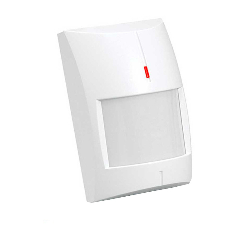
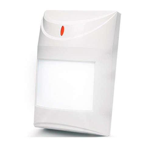
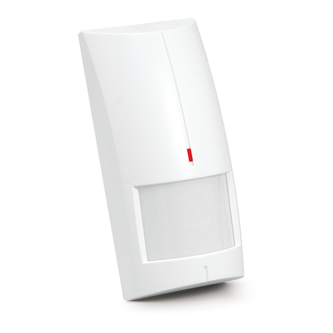
AQUA PLUS
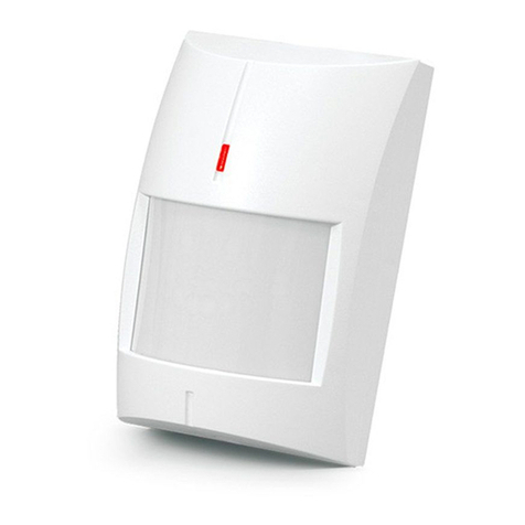
DIGITAL PASSIVE INFRARED DETECTOR
aqua_plus_en 05/09
The microprocessor-based, fully digital AQUA PLUS detector is characterized by
high sensitivity and interference resistance. Due to an advanced digital
temperature compensation feature, the device can work in a wide temperature
range. A dual element pyrosensor is used in the detector. The processor performs
two-way signal analysis, based on value and quantity.
The detector is provided with a prealarm feature. Prealarm is signaled by a short
flash of the LED after changes which do not meet the alarm criteria have been
sensed within the detector coverage area. The prealarm sensitivity depends on
what sensitivity is set on the detector pins. Frequently occurring prealarms may
cause an alarm.
For 30 seconds after the power-up, the detector remains in the starting state,
which is signalized by a rapid LED blinking. Only after this time has elapsed, the
detector will be ready to work.
The detector monitors the supply voltage. If the voltage drops below 9V (±5%) for
more than 2 seconds, the detector will signal a trouble by activation of the alarm
relay and by steady light of the LED indicator. Restoration of a minimum 9V (±5%)
voltage will turn the signaling off.
NC TMP COM 12V
NC TMP
JP1
JP2
JP3
PIR SENS.
LED ON/OFF
1
2
3
4
5
7
6
Fig. 1. View of detector electronics board.
Explanations to Fig. 1:
1 – terminals:
NC – relay (NC)
TMP – tamper contact
COM – common ground
12V – supply input
2 – red color LED to indicate:
– prealarm – short flash (approx. 120 ms);
– alarm – lit up for 2 seconds;
– starting state – blinking rapidly;
– low supply voltage – red light.
3 – pyroelement.
4 – tamper contact.
5 – scale for positioning of pyroelement against the lens (see: Fig. 7).
6 – fixing screw hole.
8 – detector configuration pins:
PIR SENS - setting detector sensitivity (see Fig. 2);
LED ON/OFF - enabling/disabling the LED signaling. The signaling is
enabled when the pins are shorted.
A
JP1
JP2
PIR SENS.
D
JP1
JP2
PIR SENS.
C
JP1
JP2
PIR SENS.
B
JP1
JP2
PIR SENS.
Fig. 2. Setting the detector sensitivity
(A – low sensitivity, B and C – medium sensitivity, D – high sensitivity)
[– pins shorted; – pins open].
Lenses
An extra wide (EWA) lens is installed in the detector. Optionally, lenses with other
characteristics (coverage patterns) can be purchased and installed.
Name Description Range Angle of view
EWA extra wide angle 15 m 141.2°
LR long range with access
zone monitoring
30 m main beam – 3 m wide (at the
end of range)
VB vertical barrier 22.5 m 2.2 m wide (at the end of range)
Table 1. Available lenses.
0 10 m 20 m
10 m
10 m
0
0
2,4 m
Fig. 3. Coverage area of a detector with EWA type lens.
Note: The detector operating range should be selected to match the size of
space where the detector will be installed. The size of the space along the
main direction of detector positioning is not to be less than 1/3 the nominal
range of the detector. Improper selection of the lens may cause excessive
sensitivity and trigger false alarms.
Installation
1. Open the housing as shown on Fig. 4.
I II
Fig. 4. Removing the cover.
2. Remove the electronics board.
3. Make suitable openings for screws and cable in the rear panel of the housing.
4. Pass the cable through the prepared opening.
5. Fix the rear housing panel to the wall or to the attached holder.
A B
DC
Fig. 5. Ways of installing the detector.
III
Fig. 6. Mounting the detector on the holder.
6. Fasten the electronics board, taking into consideration the height of detector
installation (see: Fig. 7).
h>2.4 m
B
2.4 m
A
2.4 m
h<2.4 m
C
2.4 m
D
2.4 m
h=2.4 m
2.4 m
Fig. 7. Effect of the height of installation on the detector coverage area and the
way of positioning the electronics board to optimize the area. Depending on the
mounting height, the medium scale line should be: aligned with the mark on the
enclosure (installation at a height of 2.4 m), situated above the mark (installation
higher than 2.4 m – example B) or below the mark (installation lower than 2.4 m –
example D).
7. Connect the leads to the corresponding terminals.
8. Using jumpers, set the working parameters of the detector.
9. Close the detector housing.
Start-up
1. Switch the detector power on. The LED will start blinking (if the LED ON/OFF
pins are shorted).
2. When the detector enters its working state (the LED will stop blinking), carry
out the detector range test, i.e. check that movement within the supervised
area will activate the alarm relay and lighting of the LED.
3. If necessary, change the detector sensitivity (pins PIR SENS.).
Specifications
Supply voltage................................................................................. 12 V DC ±15%
Current consumption, standby.......................................................................10 mA
Current consumption, maximum....................................................................12 mA
Relay contacts rated load (resistive)............................................. 40 mA / 16 V DC
Alarm signaling time ........................................................................................... 2 s
Detectable speed ................................................................................... 0.3...3 m/s
Security grade according to EN50131-2-2.................................................. Grade 2
Environmental class according to EN50130-5 .......................................................II
Operating temperature range ................................................................-10...+55°C
Standards complied with ........ EN50131-1, EN50131-2-2, EN50130-4, EN50130-5
Dimensions....................................................................................63 x 96 x 49 mm
Recommended installation height................................................................... 2.4 m
Weight .............................................................................................................. 90 g
SATEL sp. z o.o.
ul. Schuberta 79
80-172 Gdańsk
POLAND
tel. + 48 58 320 94 00
[email protected]
www.satel.pl
The latest EC declaration of conformity and product approval
certificates are available for downloading on website www.satel.pl

Other Satel Security Sensor manuals

Satel AQUA S User manual

Satel

Satel AQUA S User manual

Satel COBALT User manual

Satel

Satel COBALT User manual

Satel MAGENTA User manual

Satel

Satel MAGENTA User manual

Satel GREY User manual

Satel

Satel GREY User manual

Satel AQUA PRO User manual

Satel

Satel AQUA PRO User manual

Satel AQUA RING S User manual

Satel

Satel AQUA RING S User manual

Satel FD-1 User manual

Satel

Satel FD-1 User manual

Satel VD-1 User manual

Satel

Satel VD-1 User manual

Satel AQUA S User manual

Satel

Satel AQUA S User manual

Satel ASD-100 User manual

Satel

Satel ASD-100 User manual

Satel IVORY User manual

Satel

Satel IVORY User manual

Satel SLIM-DUAL-PRO User manual

Satel

Satel SLIM-DUAL-PRO User manual

Satel AQUA PET User manual

Satel

Satel AQUA PET User manual

Satel SPL-TO User manual

Satel

Satel SPL-TO User manual

Satel SLIM-DUAL-LUNA-PET User manual

Satel

Satel SLIM-DUAL-LUNA-PET User manual

Satel MGD-300 User manual

Satel

Satel MGD-300 User manual

Satel SILVER User manual

Satel

Satel SILVER User manual

Satel SLIM-PIR-LUNA-PET User manual

Satel

Satel SLIM-PIR-LUNA-PET User manual

Satel AXD-200-DG User manual

Satel

Satel AXD-200-DG User manual

Satel FD-1 User manual

Satel

Satel FD-1 User manual

Satel abax 2 ACD-220 User manual

Satel

Satel abax 2 ACD-220 User manual

Satel AFD-100 User manual

Satel

Satel AFD-100 User manual

Satel AGD-200-BR User manual

Satel

Satel AGD-200-BR User manual

Satel AMD-101 User manual

Satel

Satel AMD-101 User manual

Popular Security Sensor manuals by other brands

AJAX MotionProtect user manual

AJAX

AJAX MotionProtect user manual

Berker BLC Operation and assembly instructions

Berker

Berker BLC Operation and assembly instructions

B.E.G. LUXOMAT LC-Click-N 140 Installation and operation instruction

B.E.G. LUXOMAT

B.E.G. LUXOMAT LC-Click-N 140 Installation and operation instruction

Pepperl+Fuchs RMS-FRW manual

Pepperl+Fuchs

Pepperl+Fuchs RMS-FRW manual

3M DBI-SALA Nano-Lok XL Series instruction manual

3M

3M DBI-SALA Nano-Lok XL Series instruction manual

eufy Security Smart Buoy user manual

eufy Security

eufy Security Smart Buoy user manual

CAMDEN CM-419 Installation

CAMDEN

CAMDEN CM-419 Installation

Orno OR-CR-211 Instruction

Orno

Orno OR-CR-211 Instruction

Kistler 6021B Series instruction manual

Kistler

Kistler 6021B Series instruction manual

Extech Instruments DVA30 user guide

Extech Instruments

Extech Instruments DVA30 user guide

Levenhuk Ermenrich Wett MW10 user manual

Levenhuk

Levenhuk Ermenrich Wett MW10 user manual

Electronics Line EL-4755 manual

Electronics Line

Electronics Line EL-4755 manual

Uni-Trend UT12B operating manual

Uni-Trend

Uni-Trend UT12B operating manual

hager TRC321B quick start guide

hager

hager TRC321B quick start guide

Cree FSP-211 installation instructions

Cree

Cree FSP-211 installation instructions

Stahl FX15 Series operating instructions

Stahl

Stahl FX15 Series operating instructions

Calimet CM9-604 installation manual

Calimet

Calimet CM9-604 installation manual

SECO-LARM SLI Enforcer E-964-D390Q manual

SECO-LARM

SECO-LARM SLI Enforcer E-964-D390Q manual

manuals.online logo
manuals.online logoBrands
  • About & Mission
  • Contact us
  • Privacy Policy
  • Terms and Conditions

Copyright 2025 Manuals.Online. All Rights Reserved.