Segnalazione guasti Fault signalling
Il BL151 è dotato di un relè per la segnalazio-
ne dei guasti i cui contatti fanno capo ai mor-
setti [NA-COM-NC] / GUASTO.
The BL151 is equipped with a fault signalling
relay the contacts of which are connected to
terminals [NA-COM-NC] / GUASTO.
In assenza di malfunzionamenti: No faults:
Øi morsetti [NC] e [COM] sono collegati, Øterminals [NC] and [COM] are connected,
Ømentre il morsetto [NA] è appeso. Øwhilst terminal [NA] is disconnected.
In caso di cortocircuito o interruzione della li-
nea di alimentazione dei rivelatori: In the event of short-circuit or failure on the
power line to the detector:
Øil morsetto [NC] rimane appeso, Øterminal [NC] is disconnected,
Ømentre i morsetti [NA] e [COM] sono collegati. Øwhilst terminals [NA] and [COM] are con-
nected.
+Affinché il circuito di rilevazione guasti
funzioni, è indispensabile collegare il mor-
setto [A] del BL151 al morsetto [+B] dell’-
ultimo rivelatore d’incendio (collegamento
a 3 fili) come illustrato in figura 2.
+In order for fault signalling to operate, it
is necessary to connect terminal [A] of
the BL151 to terminal [+B] of the last fire
detector (a 3 wire connection) as illu-
strated in figure 2.
+Sui contatti [NA-COM-NC] / GUASTO può
circolare una corrente massima di 1 A. +A maximum 1 A current may circulate
on contacts [NA-COM-NC] / GUASTO.
Ripristino dei rivelatori To Reset Detectors
Un rivelatore d’incendio rimane in allarme an-
che quando sono cessate le cause che lo han-
no provocato.
A fire detector will hold alarm status even after
the cause of alarm has ceased.
Per ripristinare i rivelatori d’incendio andati in
allarme applicare la tensione di alimentazione
13.8 V) al morsetto [RST] per almeno 10 sec..
To reset the fire detectors to standby status
apply the 13.8 V voltage to terminal [RST] for
at least 10 seconds.
+Quando sul morsetto [RST] è presente
la tensione di alimentazione, i rivelatori
di incendio sono inibiti.
+When the voltage is present on the RST
terminal, the fire detectors will be inhibi-
ted.
Collegamento dei rivelatori d’incendio Connection of fire detectors
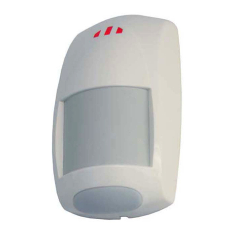
I rivelatori d’incendio RF501t, RT101 ed
RT102, vanno collegati ai morsetti [+B L.RIV.],
[-- L.RIV.] ed [A].
The RF501t, RT101 and RT102 fire detectors
should be connected to terminals [+B L.RIV.],
[-- L.RIV.] and [A].
Se si vuole la rilevazione dei guasti (vedere
paragrafo "Segnalazione guasti") eseguire i
collegamenti come in figura 2 nella quale il
morsetto [+B] dell’ultimo rivelatore viene colle-
gato al morsetto [A] del BL151.
If fault signalling is required (see the Fault Sig-
nalling paragraph) carry out the connection as
illustrated in figure 2, in which terminal [+B] of
the last detector is connected to terminal [A] of
the BL151.
In figura 1 invece è mostrato il collegamento con
soli 2 fili; in questo caso però non è possibile rile-
vare eventuali guasti sulla linea di alimentazione.
Figure 1 illustrates a 2 wire connection; in this
case, fault on the power line will not be signalled.
+Non collegare alcuna resistenza o diodo
di fine linea (R.F.L.) fra il morsetto [+B]
ed il morsetto [--] dell’ultimo rivelatore
(vedere figure 1 e 2).
A ciascun BL151 possono essere colle-
gati al massimo 10 rivelatori d’incendio.
Non collegare alcuna lampada di ripetizione
o altro dispositivo al morsetto [R] dei rivela-
tori termovelocimetrici RT101 ed RT102.
+No line end diode or resistance must be
connected to (R.F.L.) between terminal
[+B] and terminal [--] of the last detector
(see figures 1 and 2).
A maximum of 10 fire detectors may be
connected to each BL151 adapter.
Do not connect repeater lights or other
devices to terminal [R] of the Rate of
rise detectors RT101 and RT102.


