2 ASD-110 SATEL
Note: The alarm memory is cleared after exiting the test mode.
3. Installation
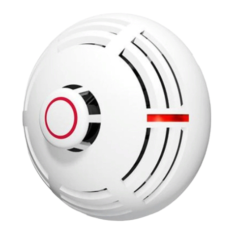
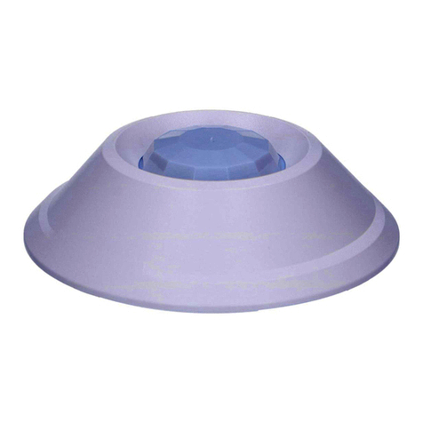
The detector is designed for indoor operation. It should be installed on the ceiling, at
a minimum distance of 0.5 meters from the walls.
Do not install the detector in places with high concentration of dust and/or
formation and condensation of water steam. The detector should not be
mounted in the vicinity of heaters and cookers.
The detector enclosure can not be closed without the battery inserted.
Be particularly careful during installation and replacement of the battery. The
manufacturer is not liable for the consequences of incorrect installation of the
battery.
The following description applies to installation of the detector which is to work within the
ABAX system. If the detector is to operate stand-alone, skip steps 5-8.
1. Remove the plastic dust cap.
2. Turn the cover counter-clockwise (Fig. 1) and remove it (Fig. 2).
3. Remove the battery and remove the protective film from it.
4. Re-install the battery.
5. Add the detector to the wireless system (see the ACU-100 controller manual, installer
manuals for INTEGRA 128-WRL or VERSA control panels).
6. Close the enclosure and temporarily fasten the detector at the future installation place.
7. Check the level of signal received from the detector by the ACU-100 controller or by the
INTEGRA 128-WRL control panel. If necessary, select another place for installation, to
ensure adequate communication quality.
8. Open the enclosure.
9. With the use of pins and screws, secure the enclosure base to the ceiling.
10.Close the detector enclosure.
11.Press and hold down the test / reset button (designated with the letter A in Figure 1) to
make sure that the detector works. Alarm should be triggered after a few seconds.
12.If any other operations which may cause contamination of the optical chamber are being
carried in the facility where the detector is installed, the detector must be temporarily
covered with a plastic dust cap.
4. Cleaning the optical chamber
The detector monitors the state of the optical chamber. Deposition of dust in the interior of
the chamber can in time lead to false alarms. Contamination of the chamber is indicated by
LED (2 flashes every 40 seconds). You should then:
1. If the detector is used in the ABAX system, start the service mode in the control panel.
2. Turn the cover counter-clockwise (Fig. 1) and remove it (Fig. 2).
3. Remove the battery.
4. Pull aside the mounting catches (Fig. 3) and remove the electronics board with the optical
chamber (Fig. 4).
5. Remove the cover from the thermistor (Fig. 5).
6. Pull aside the thermistor and its leads (Fig. 6).
7. Pull aside the mounting catch of the optical chamber (Fig. 7) and remove it (Fig. 8).
