manuals.online logo
Brands
  1. Home
  2. •
  3. Brands
  4. •
  5. Satel
  6. •
  7. Security Sensor
  8. •
  9. Satel AQUA S User manual

Satel AQUA S User manual

®
AQUA S
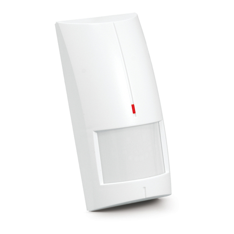
DIGITAL PASSIVE INFRARED DETECTOR
aqua_s_en 07/11
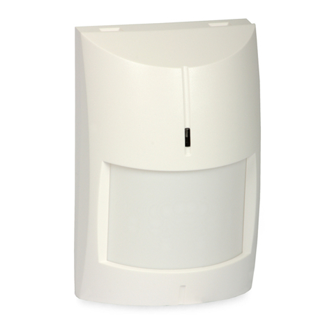
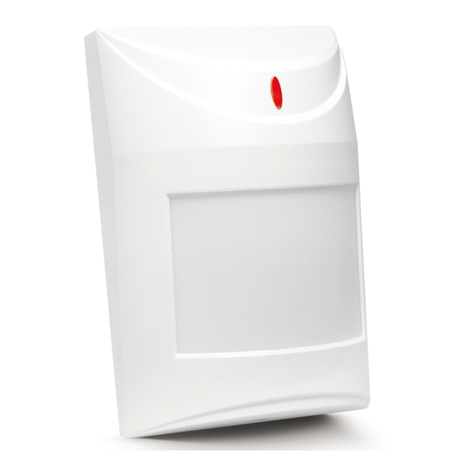
The microprocessor-based, fully digital AQUA S detector is characterized by high
sensitivity and interference resistance. A dual pyroelectric sensor is used in the
detector. AQUA S can be supplied with AC or DC 24 V voltage.
The detector is provided with a prealarm feature. Prealarm is signaled by a short
flash of the LED after changes which do not meet the alarm criteria have been
sensed within the detector coverage area. The prealarm sensitivity depends on
what sensitivity is set on the detector pins. Frequently occurring prealarms may
cause an alarm.
For 30 seconds after the power-up, the detector warms up. Only after this time
has elapsed, the detector will be ready to work. Warm-up is indicated by a rapid
LED blinking.
Fig. 1. View of detector electronics board.
Explanations to Fig. 1:
1 - terminals:
NC – relay (NC)
TMP – tamper contact
24V – supply input (AC/DC)
2 - red LED to indicate:
– prealarm – short flash (approx. 120 ms);
– alarm – ON for 2 seconds;
– warm-up – blinking rapidly;
– low supply voltage – ON.
3 - pyroelectric sensor.
4 - tamper contact.
5 - scale for positioning of pyroelectric sensor against the lens (see Figure 7).
6 - fixing screw hole.
7 - detector configuration pins:
PIR SENS. - setting detector sensitivity (see Fig. 2);
LED ON/OFF - enabling/disabling the LED signaling. The signaling is
enabled when the pins are shorted.
Fig. 2. Setting the detector sensitivity
(A – low sensitivity, B and C – medium sensitivity, D – high sensitivity)
[– pins shorted; – pins open].
Lenses
An extra wide (EWA) lens is installed in the detector. Optionally, lenses with other
characteristics (coverage patterns) can be purchased and installed.
Name Description Range Angle of view
EWA extra wide angle 15 m 141.2°
LR long range with access
zone monitoring
30 m main beam – 3 m wide (at the
end of range)
VB vertical barrier 22.5 m 2.2 m wide (at the end of range)
Table 1. Available lenses.
Fig. 3. Coverage area of a detector with EWA type lens.
Installation
1. Open the enclosure as shown on Figure 4.
Fig. 4. Removing the cover.
2. Remove the electronics board.
3. Make suitable openings for screws and cable in the enclosure base.
4. Pass the cable through the prepared opening.
5. Fix the enclosure base to the wall or to the attached bracket.
Fig. 5. Ways of installing the detector.
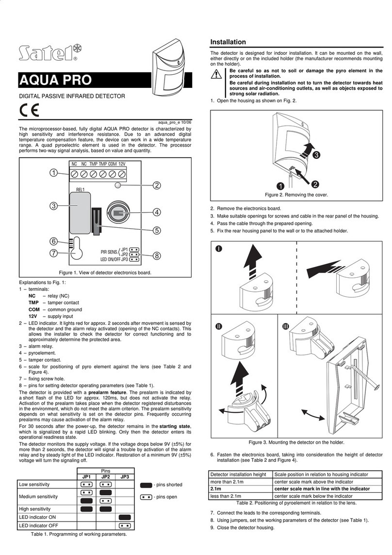
Fig. 6. Mounting the detector on the bracket.
6. Fasten the electronics board, taking into consideration the height of detector
installation (see Figure 7).
h>2.4 m
B
2.4 m
A
2.4 m
h<2.4 m
C
2.4 m
D
2.4 m
h=2.4 m
2.4 m
Fig. 7. Effect of the height of installation on the detector coverage area and the
way of positioning the electronics board to optimize the area. Depending on the
mounting height, the medium scale line should be: aligned with the mark on the
enclosure (installation at a height of 2.4 m), situated above the mark (installation
higher than 2.4 m – example B) or below the mark (installation lower than 2.4 m –
example D).
7. Connect the wires to the corresponding terminals.
8. Using jumpers, set the working parameters of the detector.
9. Close the detector enclosure.
Start-up
1. Switch the detector power on. The LED will start blinking (if the JP3 pins are
shorted).
2. When the detector is ready to work (the LED will stop blinking), carry out the
detector range test, i.e. check that movement within the coverage area will
activate the alarm relay and lighting of the LED.
3. If necessary, change the detector sensitivity (pins PIR SENS.).
Specifications
Supply voltage............................................................................24 V AC/DC ±15%
Max. current consumption (±10%) ............................................ 27 mA for 24 V AC
............................................ 14 mA for 24 V DC
Relay contacts rating (resistive load) ...................................... 40 mA / 27 V AC/DC
Alarm signaling time ........................................................................................... 2 s
Detectable speed ................................................................................... 0.3...3 m/s
Environmental class according to EN50130-5 .......................................................II
Operating temperature range ...............................................................-30...+55 °C
Maximum humidity........................................................................................93±3%
Dimensions....................................................................................63 x 96 x 49 mm
Recommended installation height................................................................... 2.4 m
Weight .............................................................................................................. 93 g
SATEL sp. z o.o.
ul. Schuberta 79
80-172 Gdańsk
POLAND
tel. + 48 58 320 94 00
[email protected]
www.satel.pl
The declaration of conformity may be consulted at www.satel.eu/ce

Other manuals for AQUA S

1

Other Satel Security Sensor manuals

Satel OPAL-GY User manual

Satel

Satel OPAL-GY User manual

Satel AMD-101 User manual

Satel

Satel AMD-101 User manual

Satel AQUA User manual

Satel

Satel AQUA User manual

Satel ARD-100 User manual

Satel

Satel ARD-100 User manual

Satel ASD-250 User manual

Satel

Satel ASD-250 User manual

Satel AQUA PRO User manual

Satel

Satel AQUA PRO User manual

Satel SILVER User manual

Satel

Satel SILVER User manual

Satel micra MXD-300 User manual

Satel

Satel micra MXD-300 User manual

Satel AQUA RING S User manual

Satel

Satel AQUA RING S User manual

Satel SLIM-PIR-PRO User manual

Satel

Satel SLIM-PIR-PRO User manual

Satel TD-1 User manual

Satel

Satel TD-1 User manual

Satel SLIM-PIR-LUNA-PET User manual

Satel

Satel SLIM-PIR-LUNA-PET User manual

Satel APD-100 User manual

Satel

Satel APD-100 User manual

Satel AVD-100 User manual

Satel

Satel AVD-100 User manual

Satel COBALT Pro User manual

Satel

Satel COBALT Pro User manual

Satel SILVER User manual

Satel

Satel SILVER User manual

Satel MGD-300 User manual

Satel

Satel MGD-300 User manual

Satel ADD-200 User manual

Satel

Satel ADD-200 User manual

Satel AGD-100 User manual

Satel

Satel AGD-100 User manual

Satel AMD-103 User manual

Satel

Satel AMD-103 User manual

Satel DMP-100 User manual

Satel

Satel DMP-100 User manual

Satel COBALT User manual

Satel

Satel COBALT User manual

Satel AOCD-260 User manual

Satel

Satel AOCD-260 User manual

Satel AQUA RING User manual

Satel

Satel AQUA RING User manual

Popular Security Sensor manuals by other brands

Vishay TSSP60 Series manual

Vishay

Vishay TSSP60 Series manual

Instar IN-6014 HD user manual

Instar

Instar IN-6014 HD user manual

FIREGUARD GLOBAL FG-BD100 Product introduction

FIREGUARD GLOBAL

FIREGUARD GLOBAL FG-BD100 Product introduction

Aritech ShatterPro 3 installation instructions

Aritech

Aritech ShatterPro 3 installation instructions

Tecnosystemi Toolsplit TSCE-300 user manual

Tecnosystemi

Tecnosystemi Toolsplit TSCE-300 user manual

CAME 001SDTE manual

CAME

CAME 001SDTE manual

steute EE RC Si 56 Series Mounting and wiring instructions

steute

steute EE RC Si 56 Series Mounting and wiring instructions

Isolite Max Series instructions

Isolite

Isolite Max Series instructions

THORLABS APD430 Series Operation manual

THORLABS

THORLABS APD430 Series Operation manual

DOL 104 0-5 V Technical user guide

DOL

DOL 104 0-5 V Technical user guide

Hytronik HIR32 All-in-One Quick Start Guide

Hytronik

Hytronik HIR32 All-in-One Quick Start Guide

ring Motion Detector 2nd Generation Z-Wave Technical manual

ring

ring Motion Detector 2nd Generation Z-Wave Technical manual

jablotron JA-160PC manual

jablotron

jablotron JA-160PC manual

Niko 351-27360 quick start guide

Niko

Niko 351-27360 quick start guide

daviteq AV10-G4-NH3 manual

daviteq

daviteq AV10-G4-NH3 manual

Visonic DUET installation instructions

Visonic

Visonic DUET installation instructions

B.E.G. LUXOMAT net PD2N-KNX-DX Mounting instructions

B.E.G.

B.E.G. LUXOMAT net PD2N-KNX-DX Mounting instructions

netvox R313FC user manual

netvox

netvox R313FC user manual

manuals.online logo
manuals.online logoBrands
  • About & Mission
  • Contact us
  • Privacy Policy
  • Terms and Conditions

Copyright 2025 Manuals.Online. All Rights Reserved.