SATO CG412DT User manual

For printer model:
Service Manual
CG4 Series
Please read this Service Manual before using this product.
Keep this document available for future reference.
CG408DT
CG412DT
Direct Thermal Type
CG408TT
CG412TT
Thermal Transfer Type

NOTE: This equipment has been tested and found to comply with the limits for a Class B digital device,
pursuant to part 15 of the FCC Rules. These limits are designed to provide reasonable protection against
harmful interference in a residential installation. This equipment generates, uses and can radiate radio
frequency energy and, if not installed and used in accordance with the instructions, may cause harmful
interference to radio communications. However, there is no guarantee that interference will not occur in a
particular installation. If this equipment does cause harmful interference to radio or television reception, which
can be determined by turning the equipment off and on, the user is encouraged to try to correct the
interference by one or more of the following measures:
• Reorient or relocate the receiving antenna.
• Increase the separation between the equipment and receiver.
• Connect the equipment into an outlet on a circuit different from that to which the receiver is connected.
• Consult the dealer or an experienced radio/ TV technician for help.
Copyrights
The contents of this document are proprietary information of SATO Corporation and/or its subsidiaries in
Japan, the U.S and other countries. No part of this document may be reproduced, copied, translated or
incorporated in any other material in any form or by any means, whether manual, graphic, electronic,
mechanical or otherwise, without the prior written consent of SATO Corporation.
Limitation of Liability
SATO Corporation and/or its subsidiaries in Japan, the U.S and other countries make no representations or
warranties of any kind regarding this material, including, but not limited to, implied warranties of
merchantability and fitness for a particular purpose. SATO Corporation shall not be held responsible for errors
containedherein or any omissions from this material or for any damages, whether direct, indirect, incidental or
consequential, in connection with the furnishing, distribution, performance or use of this material.
SATO Corporation reserves the right to make changes and/or improvements in this product and document
without notice at any time.
Trademarks
SATO is a registered trademark of SATO Corporation and/or its subsidiaries in Japan, the U.S and other
countries.
Version: GBS-CG4-01rA-15-12-09SM
© Copyright 2009 SATO Corporation.
All rights reserved.

Table of Contents
CG4 Series ServiceManual Page i
TABLE OF CONTENTS
Introduction................................................................................................................1 - 1
1.1 About this Manual........................................................................................................ 1 - 2
1.2 Features of the Printer................................................................................................. 1 - 2
1.3 Parts Identification ....................................................................................................... 1 - 3
General Specifications..............................................................................................2 - 1
2.1 Printer Basic Specifications ......................................................................................... 2 - 1
2.2 Optional Accessories Specifications............................................................................ 2 - 7
Interface Specifications............................................................................................3 - 1
3.1 Interface types ............................................................................................................. 3-1
3.2 RS232C Serial Interface.............................................................................................. 3 - 2
3.3 IEEE 1284 Parallel Interface........................................................................................ 3 - 8
3.4 Universal Serial Bus (USB) Interface......................................................................... 3 - 13
3.5 Local Area Network (LAN) Ethernet........................................................................... 3 - 15
Operation and Configuration....................................................................................4 - 1
4.1 Operator Panel............................................................................................................. 4 - 2
4.2 Operating Modes ......................................................................................................... 4 - 3
4.3 User Test Print Mode................................................................................................... 4 - 6
4.4 Factory Test Print Mode............................................................................................. 4 - 10
4.5 Operation Setting Mode............................................................................................. 4 - 13
4.6 Program Download Mode.......................................................................................... 4 - 15
4.7 Font Download Mode................................................................................................. 4 - 17
4.8 Default Setting Mode ................................................................................................. 4 - 18
4.9 HEX Dump Mode....................................................................................................... 4 - 18
4.10 Boot Download Mode............................................................................................... 4 - 19
4.11 Error Occurrence While Downloading...................................................................... 4 - 20
4.12 Factory Clear Mode ................................................................................................. 4 - 21
4.13 Factory Adjustment Mode........................................................................................ 4 - 24
4.14 Factory USB Interface Mode.................................................................................... 4 - 28
4.15 Factory USB Boot Download Mode......................................................................... 4 - 29
4.16 Printer Configurations Setting.................................................................................. 4 - 30
Troubleshooting........................................................................................................5 - 1
5.1 Error Signal Troubleshooting....................................................................................... 5 - 2
5.2 Troubleshooting Flowchart........................................................................................... 5 - 4
5.3 Interface Troubleshooting.......................................................................................... 5 - 14
5.4 Test Print Troubleshooting......................................................................................... 5 - 15
Checks and Adjustment Procedures.......................................................................6 - 1
6.1 Checking the Power Supply......................................................................................... 6 - 2
6.2 Automatic Adjustment of I-Mark and GAP Sensor Outputs ......................................... 6 - 3
6.3 Sensor checks ............................................................................................................. 6 - 3
6.4 Ribbon Tension Adjustment (For CG408TT, CG412TT only)...................................... 6 - 4
6.5 Pitch position Adjustment............................................................................................. 6 - 5
6.6 Offset position Adjustment........................................................................................... 6 - 6
6.7 Print Darkness Adjustment .......................................................................................... 6 - 7

Table of Contents
Page ii CG4 Series Service Manual
Replacement Procedures .........................................................................................7 - 1
7.1 Print Head Replacement.............................................................................................. 7 - 2
7.2 Platen Roller Replacement.......................................................................................... 7 - 4
7.3 Removal of the Bottom Housing cover ........................................................................ 7 - 5
7.4 DC Power Terminal Board Replacement..................................................................... 7 - 6
7.5 Main Circuit Board Replacement................................................................................. 7 - 7
7.6 Operator Panel (KB) Board Replacement.................................................................... 7 - 8
7.7 Top Cover Open Sensor Replacement...................................................................... 7 - 10
7.8 Stepper Motor Replacement...................................................................................... 7 - 11
7.9 I-Mark/Gap Sensor Replacement .............................................................................. 7 - 12
7.10 Ribbon End Sensor Replacement............................................................................ 7 - 14
7.11 Torque Limiter (Supply Unit) Replacement.............................................................. 7 - 15
7.12 Torque Limiter (Ribbon Wind-up Unit) Replacement............................................... 7 - 16
7.13 Cutter Kit/ Board/Unit Replacement (Optional)........................................................ 7 - 17
7.14 Dispenser Kit/ Roller/ Label Sensor Replacement (Optional).................................. 7 - 19
7.15 Linerless (Non sepa) Label Sensor Replacement (Optional)................................... 7 - 21
7.16 Real Time Clock Battery Replacement (Optional)................................................... 7 - 22
Appendix....................................................................................................................8 - 1
8.1 Optional Accessories - Cutter ...................................................................................... 8 - 2
8.2 Optional Accessories - Dispenser................................................................................ 8 - 5
8.3 Optional Accessories - Linerless (Non sepa)............................................................... 8 - 8
8.4 Optional Accessories - Real Time Clock (RTC) Kit.................................................... 8 - 10
8.5 Positions of sensors and options............................................................................... 8 - 11
8.6 Operation Mode Selection ......................................................................................... 8 - 12
8.7 Base Reference Point................................................................................................ 8 - 13
8.8 Paper End.................................................................................................................. 8 - 15
8.9 Ribbon End................................................................................................................ 8 - 16
Sato Group of Companies........................................................................................9 - 1
Sato Group of Companies ................................................................................................. 9 - 2

Section 1: Introduction
CG4 Series Service Manual Page 1-1
INTRODUCTION

Section 1: Introduction
Page 1-2 CG4 Series Service Manual
1.1 ABOUT THIS MANUAL
This service manual provides all of the information required for printer maintenance and repair by SATO
approved personnel. For the repair technician, this manual is intended to compliment, and to be used as an
extension of operator manual.
This manual also incorporates the use of special information boxes. Examples of these boxes and the type of
information provided in each, are below.
A comprehensive Table Of Contents provided at the front of this manual facilitates rapid movement within.
The contents identify the different unit sections and their respective sub-sections. Each references the page
number of their commencement.
The pages of this manual has embedded headers and footers to assist the user in identifying his or her exact
position within the manual. The header provides the section number followed by its name. The footer
identifies the product and the page number.
Page enumeration is two-part with each separated by a hyphen. The first character set references the section
number and the second identifies the page number. Page numbers begin with the numeral (1) one at the
commencement of a new section and ascends sequentially.
1.2 FEATURES OF THE PRINTER
The CG4 Series is 4 inch Compact Desktop printer (Thermal Transfer or Direct Thermal). With a 32-bit RISC
CPU, 4 ips print speed, and 4MB Flash Memory, the CG4 Series is an economical printer with numerous
features making it suitable for a wide range of applications. The key features of the CG4 Series are:
• High Print Resolution with crisp printing quality (203dpi or 305dpi)
• Multiple Interface
• Cutter and Dispenser Printer Options
• Linerless Label Support
• Easy Media Loading
• Standalone Capability using Keypad
• Tool-less changing of print head and platen roller for easier maintenance
• Codepage Support and Emulations
• Anti-Microbial casing is ideally suited for clinical environments or food processing industry
• Safety Top Cover Latch
• Distinctive Chassis color
WARNING:
PROVIDES INFORMATION THAT, IF UNHEEDED, MAY RESULT IN
PERSONAL INJURY.
CAUTION:
PROVIDES INFORMATION THAT, IF UNHEEDED, MAY RESULT IN
EQUIPMENT DAMAGE.
NOTE: Provides helpful hints to assist in performing the tasks at hand.

Section 1: Introduction
CG4 Series Service Manual Page 1-3
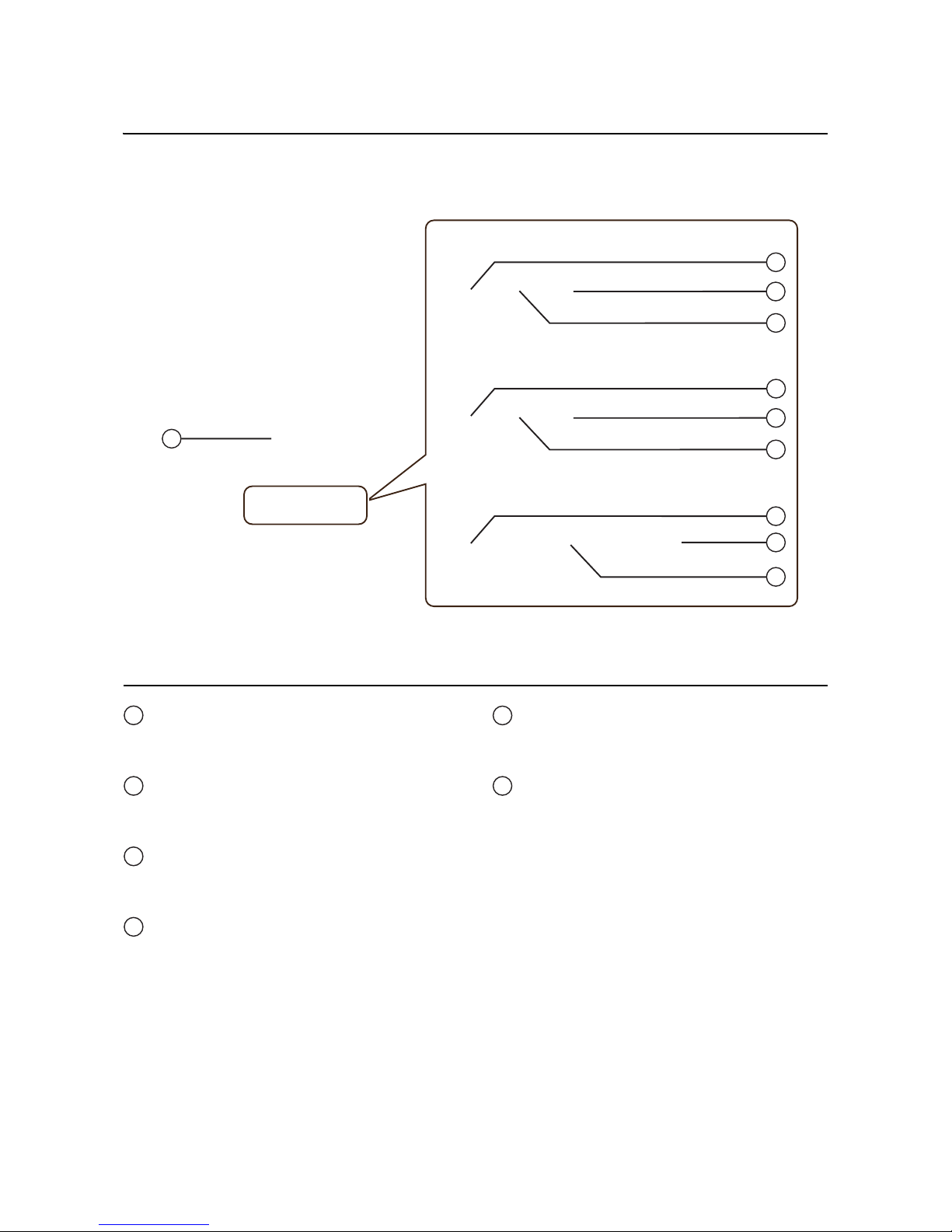
1.3 PARTS IDENTIFICATION
1
2
3
4
7
5
6
8
Front view
Operator panel
It consists of two contact buttons and two
LED indicators (green and red).
Top cover
Open this cover to load the media and ribbon.
Cover open/close latch
Pull these latches on both sides of the printer
forward to open the Top cover of the printer.
Media ejection slot
Opening for media output.
POWER button
Press this button to turn the power on or off.
FEED/LINE button
Press this button to select the printer status
(online/ offline) or to feed the media.
ERROR LED indicator
The LED lights or blinks red when an error is
detected in the printer.
During printer configuration setting, the
ERROR indicator responses in conjunction
with the ON LINE (POWER) indicator to show
the modes of the printer.
ON LINE (POWER) LED indicator
The LED lights green when the printer is online
and blinks green when the printer is offline.
During printer configuration setting, the ON
LINE (POWER) indicator responses in
conjunction with the ERROR indicator to show
the modes of the printer.
1
2
3
4
5
6
7
8
Section 1: Introduction
Page 1-4 CG4 Series Service Manual
1.3 PARTS IDENTIFICATION (cont’d)
9
USB and RS232C interface on-board
10
USB and LAN interface on-board
USB and IEEE interface on-board
11
10
10
11
11
12
13
14
Back view
Media inlet
An opening for Fan-folded media or media
from unwinder to feed in to the printer.
DC input power terminal
Supplies power to the printer by inserting the
power cable via the AC adapter.
USB interface terminal
To connect printer to the host computer using
the USB interface.
RS-232C interface terminal
To connect printer to the host computer using
RS-232C interface.
Or, to connect the optional Keypad, Scanner or
Smart keyboard to the printer.
LAN interface terminal
To connect printer to the host computer using
LAN interface.
IEEE interface terminal
To connect printer to the host computer using
IEEE interface.
9
10
11
12
13
14
Section 1: Introduction
CG4 Series Service Manual Page 1-5
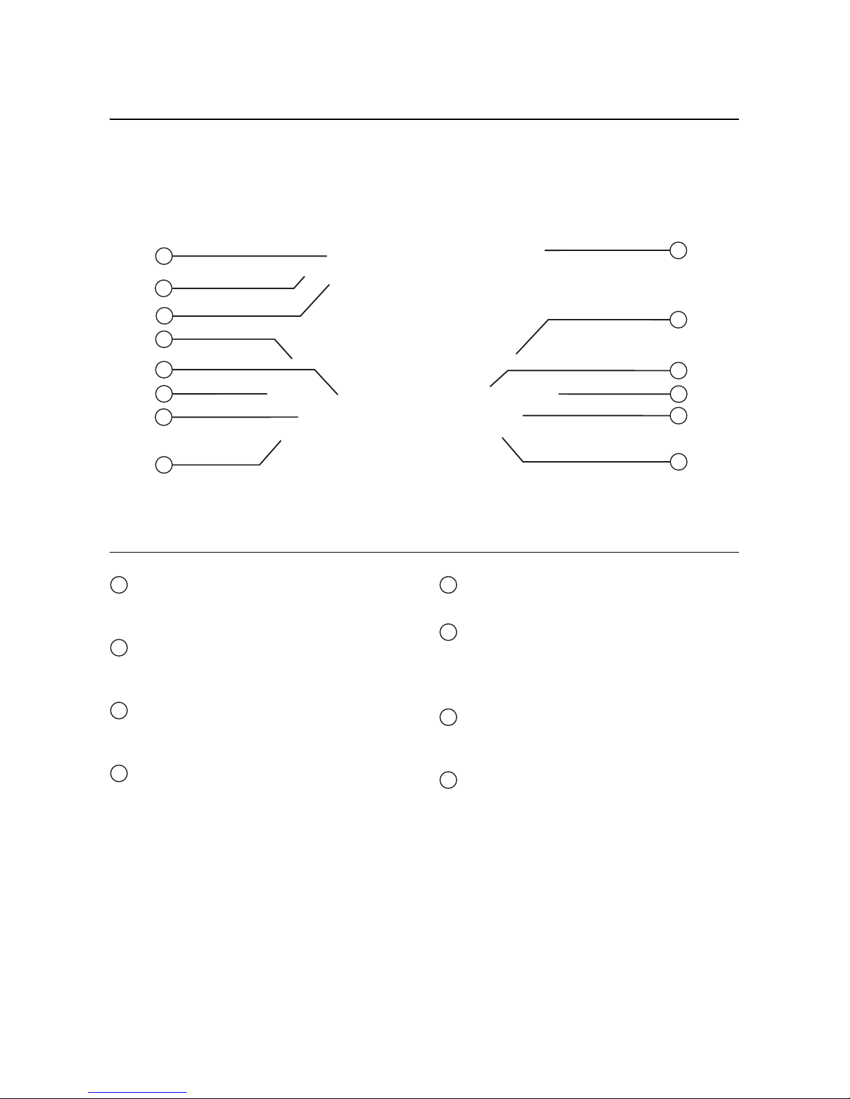
1.2 PARTS IDENTIFICATION (cont’d)
CG408DT/ CG412DTCG408TT/ CG412TT
15
20
16
17
18
19
21
22
15
18
20
19
21
22
Internal view when Top cover is opened
Print head
This component is used to print on the media.
Perform maintenance at regular intervals.
Ribbon unit
Used to load the ribbon and wind up the used
ribbon.
Pull out lever
This is used to pull out the ribbon unit from the
top cover for ribbon loading.
Roll media holder
To hold the roll media.
Media guide slide lever
Set to meet the size of the media used.
Media guide and I-Mark/ Gap sensor
A guide for the media to feed properly.
Detects the I-Mark on the media or gap of the
label.
Platen roller
This roller feeds the media. Perform
maintenance at regular intervals.
Optional device compartment
Used to install optional cutter, dispenser or
linerless (Non sepa) unit.
15
16
17
18
19
20
21
22

Section 1: Introduction
Page 1-6 CG4 Series Service Manual
This page is intentionally left blank
Other manuals for CG412DT
1
This manual suits for next models
3
Table of contents
Other SATO Printer manuals

SATO
SATO CT 400 User manual

SATO
SATO M-8485Se Series User manual

SATO
SATO CL408e User manual

SATO
SATO LC400e Series Owner's manual

SATO
SATO GT408e User manual

SATO
SATO SX4M User manual

SATO
SATO M8460S User manual

SATO
SATO CL-408 Use and care manual

SATO
SATO Argox X-1000VL User manual

SATO
SATO CT424i User manual

SATO
SATO CL-408 Owner's manual

SATO
SATO M10e Series User manual

SATO
SATO CL4NX RIDF User manual

SATO
SATO CL4NX RIDF User manual

SATO
SATO XL400 Use and care manual

SATO
SATO TG3 Series User manual

SATO
SATO M-8400 User manual

SATO
SATO SG112-ex Release note

SATO
SATO Argox D4-280plus User manual

SATO
SATO GL408e User manual


