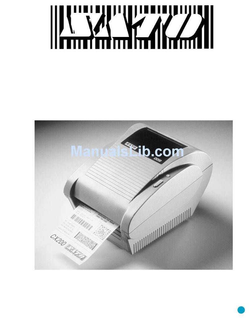
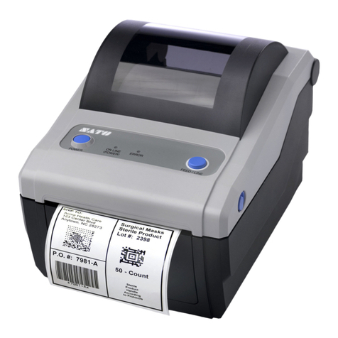
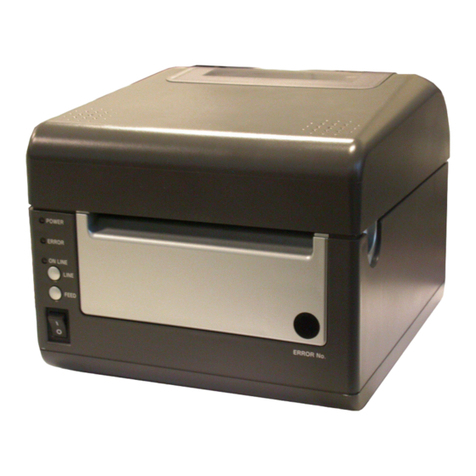
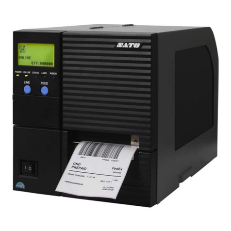
SATO CX400 User manual

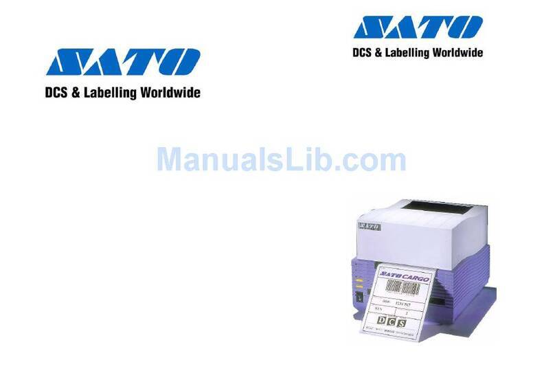
SATO CX400 Service Manual
CX400
DESKTOP PRINTER
SERVICE MANUAL

Warning: This equipment complies with the requirements in Part 15 of FCC rules for a Class A
computing device. Operation of this equipment in a residential area may cause unacceptable
interference to radio and television reception requiring the operator to take whatever steps nec-
essary to correct the interference.
All rights reserved. This document, nor any part of it, may be reproduced or issued to third parties
in any form without the express permission of SATO America, Inc. The material in this document
is provided for general information only and is subject to change without notice. SATO America,
Inc. does not assume responsibility for any errors or omissions.
06 Nov 03
SATO GROUP OF COMPANIES
BARCODE SATO
INTERNATIONAL PTE LTD
438A Alexandra Road #05-01/ 02,
Alexandra Technopark,
Singapore 119967
Tel: 65-6271-2122
Fax: 65-6271-2151
Website: www.barcodesato.com
Email: [email protected]
SATO AMERICA INC.
10350 Nations Ford Road Suite A,
Charlotte, NC 28273
Tel: 1-704-644-1650
Fax: 1-704-644-1662
Website: www.satoamerica.com
Email: [email protected]
SATO UK LTD
Valley Road, Harwich, Essex England
Co12 4RR, United Kingdom
Tel: 44-1255-240000
Fax: 44-1255-240111
Website: www.satouk.com
Email: enquiries@satouk.com
SATO EUROPE NV
Leuvensesteenweg 369, 1932 Sint- Stevens-Woluwe, Brussels, Belgium
Tel: 32 (0)-2-788-80-00
Fax: 32 (0)-2-788-80-80
Website: www.sato-europe.com
Email: [email protected]
SATO DEUTSCHLAND GMBH
Schaberweg 28, 61348
Bad Homburg, Germany
Tel: 49 (0)-6-1726-8180
Fax: 49 (0)-6-1726-818-199
Website: www.sato-europe.com
Email: [email protected]
SATO POLSKA SP Z O.O.
Ul Okolna 2, 50-422 Wroclaw
Tel: 48-71-335-23-20
Fax: 48-71-335-23-25
Website: www.sato-europe.com
Email: [email protected]
SATO SHANGHAI CO, LTD
11 Floor, D, Pudong South Road 1111,
Pudong New Area, Shanghai,
China 200120
Tel: 86 (0)-21-58307080
Fax: 86 (0)-21-58307978
Website: www.barcodesato.com
Email: [email protected]
BAR CODE SATO ELECTRONICS (S) PTE LTD
438A Alexandra Road #05-01/02,
Alexandra Technopark, Singapore 119967
Tel: 65-6271-5300
Fax: 65-6273-6011
Website: www.barcodesato.com
www.satosingapore.com
Email: sales@satosingapore.com
SATO BAR CODE & LABELLING
SDN BHD
Suite B-08-11&12, Block B Plaza Mont' Kiara, No.2, Jalan Kiara Mont'
Kiara,
50480 Kuala Lumpur, Malaysia
Tel: 60-3-6203-5950
Fax: 60-3-6203-1209
Website: www.barcodesato.com
Email: [email protected]
BARCODE SATO (THAILAND) CO., LTD
370/8 Supattra Building, 5th Floor, Rama9 Road, Bangkapi, Huay Kwang
Bangkok 10320, Thailand
Tel: 662-719-7780-3
Fax: 662-719-7784
Website: www.barcodesato.com
Email: sales@satothailand.co.th

SATO CX-400 Service Manual
TABLE OF CONTENTS
INTRODUCTION
General Description 1-1
Theory of Operation 1-1
Switches and Indicators 1-2
Connection Ports 1-3
Monitoring Sensors 1-4
Operational System 1-5
ACCESSORIES INSTALLATION
Cutter Attachment 2-1
Dispenser Attachment 2-3
Font Module 2-5
Firmware Upgrade 2-5
OPERATIONAL SETUP
Media Loading 3-1
Ribbon Loading 3-2
Input/Output Connections 3-3
Media Sensor Calibration 3-3
Media Index Sensor Calibration 3-4
Dispenser Sensor Calibration 3-4
TROUBLESHOOTING
Problem Isolation 4-1
Self-Diagnosis Label 4-2
MAINTENANCE
Cleaning 5-1
Print Head Replacement 5-1
Main Circuit Board replacement 5-3
Platen Roller Replacement 5-6
TECHNICAL DATA
Physical Properties 6-1
Enviromental Specifications 6-1
Power requirements 6-1
Printer Performance 6-1
Printer Specifications 6-1

SATO CX400 Service Manual
Media Specifications 6-2
Ribbon Specifications 6-2
Serial Interface Specifications 6-2
Regulatory Approvals 6-3
TECHNICAL DATA
BLOCK DIAGRAMS
System Block Diagram 7-1
Control Board Block Diagram 7-2
Panel Board Schematic 7-2
Sensor Board Schematic 7-3
Main Board Wiring Diagram 7-3

SATO CX400 Service Manual PN 9001110A Page 1-1
1
INTRODUCTION
This manual is laid out in a manner consistant with the product discussed and provides all of the
information required for general printer setup, operation, troubleshooting, and maintenance. For
specialized programming, refer to the Programming Manual also provided with the product.
GENERAL DESCRIPTION
SATO CX400 printers are compact desktop printers designed especially for bar code labeling
and tagging. The CX uses SATO Command Language, making it simple to integrate with other
SATO models.
Designed for convenience, the CX has many advanced features such as larger media capacity,
user replaceable print head and platen, a high lift print head carriage that makes it easy to clean
and load supplies. The printer is also designed to use eye-mark or gap-label sensing
The CX400 uses a single sensor element for both direct thermal and thermal transfer printing.
The printing method may be selected by using configuration settings in the software program or
by sending the commands directly to the printer. The current setup may be determined by
printing a self-test label which identifies all setup parameters.
A slot in the rear of the unit permits external feeding of media for larger rolls with greater linear
feet.
THEORY OF OPERATION
When activated, the media and ribbon (where applicable) are fed conjunctively past the print
head by an integrated drive train. The drive train is electric motor driven, coupled to a gear
configuration located on the left side of the printer chassis. Paper guides within the chassis
assembly ensure that the media remains properly positioned during the printing process and is
fed unimpeded through the front cover. The exhausted ribbon material is rewound onto a take-up
core installed within drive train driven spindles.
A series of strategically located sensors sends signals to the processing unit. The processing unit
in turn sends response signals to the various features based on programmed and recieved data.
Correct signals initiates print head activity.

Section 1: Introduction
Page 1-2 PN 9001110A SATO CX400 Service Manual
Primary Components, Figure 1-1
SWITCHES & INDICATORS
Power Switch A two position switch that controls power to the printer.
When the “0” position is pressed, power is removed from
the printer. When the “1” position is pressed, power is
supplied to the printer.
Feed Key Press and hold during startup for test label.
Press during printing to pause.
Press during pause to feed a blank label or print the
duplicate of the prior label.
Press to reset the printer to the factory settings.
Power Indicator Continuously illuminated when functional.
Blinks when a malfunction has occured.
Cover
Housing
Platen Roller
Base
Paper Guides
Printer Assembly
Print Head Assembly
Chassis Assembly
Paper Holder
Front Cover

Section 1: Introduction
SATO CX400 Service Manual PN 9001110A Page 1-3
Switches and Indicators, Figure 1-2
Error Indicator Not illuminated when the printer is operational.
Blinks when a malfunction has occured.
CONNECTION PORTS
Parallel Port Located on the left rear side of the printer. Permits PC
connection for advanced programming, control, and
operation.
Serial Port Located on the right rear side of the printer. Converts the
serial port signal to/from the micro-controller to RS232
voltage level. Also permits PC connection for advanced
programming, control, and operation.
VAC Power Supply Port Located centrally on the rear of the printer. Permits the
connection of the voltage supply transformer.
SWITCHES & INDICATORS
DETAIL
Feed Button
Error Indicator
Power Indicator
Power Switch

Section 1: Introduction
Page 1-4 PN 9001110A SATO CX400 Service Manual
Connection Ports, Figure 1-3
Extension Connection Port Accessible from the front of the printer and is located
behind the face cover. Permits the connnection of optional
extension modules.
MONITORING SYSTEMS
Media Index Sensor Determines the print location upon the label by detecting a
label gap or eye mark and then stepping the media to the
print position.
Ribbon Sensor Allows the printer to continuously monitor the presence of
ribbon when operating in the thermal transfer mode.
Dispenser Sensor Monitors the presence of a label in the dispenser. When
the label is removed from the dispenser, the next label will
be prompted
Print Head Open Sensor Detects when the print assembly is not latched into the
print position.
CONNECTION PORTS
Extension Port
Serial Port
VAC Power Supply Port
Parallel Port
Rear View
Front View

Section 1: Introduction
SATO CX400 Service Manual PN 9001110A Page 1-5
OPERATIONAL SYSTEMS
MicroController The SH7034 microcontroller utilizes a 16 bit external and
32 bit internal data bus based on the Hitachi SH1.
Flash Memory Has 2M bytes of Flash ROM located on the main board for
Firmware, character, and bar code font storage. The flash
ROM has a total size of 1M x 16 bit.
DRAM The 2 MB of DRAM is located on the main board. Volatile
data such as working buffers and parameters are
allocated here.
EEPROM On board memory is 128 Bytes.
RS232 Transceiver Converts the serial port signal to and from the
microcontroller to the RSR232C voltage levels.
Centronics Interface The data recieved from the host is transmitted to the
micro-controller.
Ouput Ports The ports control the motor, LED, media sensor, 24 volt
relay, and interface fault conditions.
Relay Removes the 24 volt supply to the thermal print head
during the transient period while the power is being
switched on. Otherwise the thermal print head may be
damaged.
Extension Connection Port Permits the connnection of all optional extension modules.
Configuration Jumper Selects the systems configuation.
Boot/Normal Is a two position switch that when in the normal position,
allows the program on the expansion board to be
executed only after the power has been reset. When in the
boot position, the boot program will be executed first. This
permits the CPU to reload a program into the on board
Flash ROM after complete corruption. The default setting
is in the normal position.

SATO CX400 Service Manual PN 9001110A Page 2-1
2
ACCESSORIES INSTALLATION
Optional accessories are those hardware and software items that may be purchased and used in
conjunction with the basic printer package. Namely, these are the cutter attachment, dispenser
attachment, and font module. Since the hardware options affect the method of operational setup,
they must be installed prior to any setup activities. If applicable, refer the relative procedure
below for specific instructions on accessory installation before proceeding to the Operational
Setup unit.
CUTTER ATTACHMENT
The cutter assembly is an attachment for the automated cutting of labels, tags, or tickets. A back
feed function is included for retracting the label back to the first print position after cutting. The
following procedure provides detailed instructions on cutter assembly installation and assumes
that the unit is without additional attachments that may pose an impediment to cutter installation.
CAUTION: Printer electronics are susceptable to static discharge.
Ensure appropriate grounding measures are taken before
beginning any activity inside the printer.
1. Turn off power and disconnect power supply cord.
2. Lift cover (Figure 2-1, 1) to expose print assembly (2).
3. Simultaneously, press the two purple buttons located on the top side of print assembly (2)
and pivot upward.
4. Remove the two screws (3) securing front cover (4) to cover hinge (5).
5. If peeler (6) is present, remove screw (7) and manipulate rightward. Lift away peeler (6).
6. Pry power switch (Figure 2-2, 8) from housing (9) and disconnect leads.
7. Remove the two screws (10) securing housing (9) to base assembly (11).
8. Manipulate housing (9) from base assembly (11) and lift away.
NOTE: Pull the lower front edge of the housing away from the base
assembly, then begin manipulating the housing upward.
9. Plug daughter board (not shown) into port JP29 of mother board (12).
10. Direct the two leads of daughter board through the power switch slot of housing (9).
11. Tuck the prior two power switch leads safely away within the housing unconnected.
12. Manipulate housing (9) onto base assembly (11) oriented as was removed.
13. Secure housing (9) to base assembly (11) using two screws (10).
14. Plug power switch (8) into the two leads of daughter board.

Section 2: Accessories Installation
Page 2-2 PN 9001110A SATO CX400 Service Manual
Cutter Installation, Figure 2-1
15. Insert power switch (8) into its respective slot of housing (9) oriented with the on position
upward.
16. Plug cutter assembly lead (13) into external connector (14).
17. Manipulate cutter assembly (15) into the face of printer chassis (16).
18. Secure cutter assembly (15) to printer chassis (16) by applying screw (17) to their upper
right corner.
NOTE: When properly installed, the tab of the cutter assembly
bracket shall insert into the slot of the printer chassis and the cutter
will nest there as the peeler cover prior to removal.
19. Ensure print media and ribbon are properly loaded in the printer.
20. Lower the print assembly and latch in position.
21. Close cover, connect power supply cord, and apply power.
22. Send the following command stream to enable: <ESC>A <ESC>CK1 <ESC>Z.
7
1
4
3
2
1
5
6

Section 2: Accessories Installation
SATO CX400 Service Manual PN 9001110A Page 2-3
Cutter Installation, Figure 2-2
DISPENSER ATTACHMENT
The dispenser assembly incorporates an integrated label sensor as part of the monitoring
feature. The sensor identifies the presence of a label and prevents the printing of the next label
until it is removed.
The following procedure provides detailed instructions on dispenser and dispenser sensor
installation. The procedure assumes that the unit is without additional attachments that may pose
an impediment to sensor installation.
CAUTION: Printer electronics are susceptable to static discharge.
Ensure appropriate grounding measures are taken before
beginning any activity inside the printer.
8
9
10
11
12
17
16
15
13
DETAIL
14
8
9
10
11
12
17
16
15
13
DETAIL
14

Section 2: Accessories Installation
Page 2-4 PN 9001110A SATO CX400 Service Manual
Dispenser Installation, Figure 2-3
1. Turn off power and disconnect power supply cord.
2. Lift cover (1) to expose print assembly (2).
3. Simulataneously, press the two purple buttons located on the top side of print assembly (2)
and pivot upward.
4. Remove the two screws (3) securing cover (4) to cover hinge (5) and lift away.
5. Remove clips (6) and (7) from the left and right ends of roller shaft (8) respectively.
NOTE: Before removing the retaining clips from each end of the
roller shaft, it is advised that their orientation be observed and
noted.
16
10
4
3
2
1
5
14
15
4
REARVIEW
7
11
9
10
6
8
12
13

Section 2: Accessories Installation
SATO CX400 Service Manual PN 9001110A Page 2-5
FONT MODULE
The font module stores special font types and characters. The maximum capacity options of the
font module is 2 M or 4 M bytes.
FIRMWARE UPGRADE
The printer’s operating systems software may be upgraded or reloaded through the parallel port
located on its back side. Connect the parallel interface cable supplied with the printer to the
computer LPT1 port and the printer parallel port. Place the Firmware upgrade disk in the
computer and follow the instructions in the Readme.TXT file.
6. Manipulate roller shaft (8) with roller (9) from front cover (4).
7. Apply sensor (10) to cover (4) as design dictates and secure using screw (11).
8. Insert the connector end of sensor (10) through the left bracket of cover (4).
9. Insert roller shaft (8) into roller (9) and manipulate into brackets of cover (4).
10. Secure the roller assembly with clips (7) and (6) to the right and left ends of shaft (8)
respectively.
11. Reapply cover (4) to cover hinge (5) and secure using screws (3).
10. Observe to ensure that despenser sensor (10) wire is oriented so that it is not being
pinched.
CAUTION: Ensure that the left clip does not pinch the sensor wire
as it passes through the cover mounting brackets.
11. Plug dispenser sensor (10) into external connection port (12).
12. Apply wire clamp (13) to sensor (10) wire.
13. If not already present, insert dispenser (14) into the mounting slots of printer chassis (15)
oriented so that their mounting orifices are aligned.
NOTE: The dispenser must be inserted into the right side slot first,
then manipulated into the left slot. The peeler mounting orifice is
located on the front right side of the printer chassis above the
external connection port.
14. Secure dispenser (14) and clamp (13) using screw (15).
15. Ensure that print media and ribbon are properly loaded in the printer.
16. Lower and latch print assembly (2) into operational position.
17. Close cover (1), connect power supply cord, and apply power.
18. Set the E2PROM through commands: <ESC>A <ESC>CK0 <ESC>Z.

Section 2: Accessories Installation
Page 2-6 PN 9001110A SATO CX400 Service Manual
1. Load the printer with ribbon and media as required.
2. Turn the printer on and allow 3 seconds to power up.
3. Enter the MS-DOS mode on the computer.
4. Type “X:SATO” (were X is the location fo the Firmware Upgrade file) at the DOS prompt.
5. Allow 5 minutes for the power and error LED’s to begin blinking in synchronicity.
6. Toggle the power switch off and then on again to complete the process.
7. Press and hold the printer feed button until it begins printing a self-testing label.
8. Switch the printer off and then on again to return to operation mode.
9. Examine the self-test label contents to ensure a correct upgrade or reload.
10. Repeat as necessary until the printed check sum is 0000.
11. Disconnect computer from the parallel port.
NOTE: The check sum value should always be 0000. Otherwise,
there are error bits in the onboard flash memory. The sum value is
the last four characters printed in the upper left row of the self-test
label. Refer to Self-Diagnosis in the Troubleshooting section of his
manual if still unsure.

SATO CX400 Service Manual PN 9001110A Page 3-1
3
OPERATIONAL SETUP
This section provides all guidance and instructions necessary for simple printer setup and
operation. The CX-400 printer is delivered factory calibrated and should not require calibration
upon initial setup.
However, the use of off-brand media or ribbon often has an adverse operational effect. Thusly,
load the consumables and attempt operation to determine if calibration is necessary.
MEDIA LOADING
Media must be loaded, and in the same manner, regardless of whether direct thermal or thermal
transfer printing is to be performed. However, following media installation, ensure that the correct
printer program is also loaded
NOTE: To assist in the instruction of media loading, the print
assembly has been removed from the illustration below to
provide a better view of more important features. The actual
printer will have the print assembly attached. The print
assembly is not removable.
1. Lift cover (Figure 3-1, 1) to expose the print assembly.
2. Simultaneously, press the two purple buttons located on the top side of the print assembly
and pivot upward.
3. Unwrap the new media (2) and unwind a few labels from the roll.
4. Separate paper roll holder (3) and insert media roll (2) so that it unwinds from the bottom.
5. Lock paper roll holder (3) into position by the downward movement of the purple switch
attached.
6. Separate purple paper guides (4) and feed media (2) across chassis between them.
7. Slide paper guides (4) together to make light contact with each side of media (2)
8. Pull media (2) forward and feed it through the discharge slot of cover (5).
9. Lower and press print head assembly into operational position.
10. When the error LED stops blinking, press the feed button to begin printing.

Section 3: Operation
Page 3-2 PN 9001110A SATO CX400 Service Manual
Media Loading, Figure 3-1
RIBBON LOADING
Perform the following procedure only if thermal transfer printing is desired. If thermal transfer
printing is desired, program the printer accordingly. Refer to the Programming Manual for
guidance.
1. Lift cover (Figure 3-2, 1) to expose print assembly (2).
2. Simultaneously, press the two purple buttons (3) located on the top side of print assembly
(2) and pivot upward.
3. Place ribbon roll (4) between ribbon supply spindles (5) so that the coated side is oriented
outward.
NOTE: The coated side has the duller sheen. If still unsure,
scratch each side to determine which is coated.
NOTE: The ribbon supply spindle is located on the lower
side of the print assembly.
MEDIA
4
1
2
3
5

Section 3: Operation
SATO CX400 Service Manual PN 9001110A Page 3-3
Ribbon Loading, Figure 3-2
INPUT/OUTPUT CONNECTIONS
For typical operation, the voltage power transformer is the only required connection. Its
connection port is centrally located on the rear of the printer. Refer to the Introduction unit of this
manual for specific identification if necessary.
The parallel and serial ports are required for sending commands and data from the host to the
printer. Instructions for their use may be found in the Programming manual. Their locations are
also in the rear of the printer.
MEDIA SENSOR CALIBRATION
The media dispenser sensor monitors media presence. When the print media is exhausted, the
sensor signals an error condition. If the sensor incorrectly detects the presence of print media
available for use, the dispenser sensor may require calibration. Perform the applicable steps
below relative to the media type used.
.
NOTE: The ribbon cores and spindles for supply and take-up
are notched. When a core is properly installed, it will nest
with its respective spindle.
4. Feed enough of ribbon (4) out so as to insert take-up core (6) onto rewind spindles (7).
5. Advance purple thumbwheel (8) of rewind spindles (7) to take up ribbon slack.
1
RIBBON
RIBBON
RIBBON
2
5
4
1
23
7
6
8
4

Section 3: Operation
Page 3-4 PN 9001110A SATO CX400 Service Manual
Figure 3-3, Label Stock Diagram
For Eye-Mark Detection
1. Install both printer ribbon and print media while in the TT mode.
2. Send the following commands to the printer: <ESC>A <ESC>&11 <ESC>Z.
3. Allow 5 seconds for the printer to complete the process.
For Label-Gap Detection
1. Install print media into the printer while.
2. Place the printer in the TT mode by sending <ESC>A <ESC>CP1 <ESC>Z.
3. Send the following commands to the printer: <ESC>A <ESC>&10 <ESC>Z.
4. Allow 5 seconds for the printer to complete the process.
LABEL
BACKING PAPER INSIDE EDGE LABEL INSIDE EDGE
GAP, NOTCH, OR BAR WIDTH
EYE-MARK ON
LABEL
LABEL FEED DIRECTION
MIN: 0.04" (2mm)
MAX. 1.0" (25mm)
0.39" (10mm)
MIN LABEL PITCH
0.06" (1.5mm) = NON-PRINT
MIN. LENGTH
= 0.59" (15mm)
PRINT HEAD
0.06" (1.5mm) =NON-PRINT
0.25" (5.0mm)
0.75" (19mm)
BOTTOM OF LINER

Section 3: Operation
SATO CX400 Service Manual PN 9001110A Page 3-5
MEDIA INDEX SENSOR CALIBRATION
CX-400 Printers can use an eye-mark (black bar) label gap or label notch sensing. The gap and
notch sensor is a transmissive or see-thru type with an infrared light source directed through the
label from above and detected by a separate receiving sensor underneath the label liner tag. A
reflective sensor is used to detect eye-marks printed on the bottom of the label liner or tag. The
eye-mark must not reflect more than 12 % of the light. Since the same receving sensor is used
for all three types of sensing, it must be calibrated with the media that will be used. For thermal
transfer printing, the ribbon must be installed while the calibration is performed.
Media sensor calibration may also be required if the printer frequently fails to print, has excessive
print position variance, or the print image is mis-located. Calibration may be performed by either
clicking on the calibration buttons of the Label Gallery Free software, through the Windows
Printer Driver, or more directly by sending printer commands to the printer. To signify a successful
calibration, the printer will feed 6 linear inches of label upon completion. Perform the applicable
steps below relative to the media type used.
DISPENSER SENSOR CALIBRATION
For Eye-Mark Detection
1. Install both printer ribbon and print media while in the prper mode (DT or TT).
2. Send these commands to the printer: <ESC>A <ESC>CI1 <ESC>CA <ESC>Z.
3. Allow the printer to feed 6 linear inches of labels to complete the calibration.
For Label-Gap Detection
1. Install the print media while in the TT mode.
2. Send these commands to the printer: <ESC>A <ESC>CI2 <ESC>CA <ESC>Z.
3. Allow the printer to feed 6 linear inches of labels to complete the calibration
For Thermal Transfer
1. Place a label in the discharge slot over the sensor.
2. Send the following commands to the printer: <ESC>A <ESC>&P1 <ESC>Z.
3. Allow 5 seconds for the printer to complete the process.
For Direct Thermal
1. Place a label in the discharge slot over the sensor.
2. Send the following commands to the printer: <ESC>A <ESC>&P0 <ESC>Z.
3. Allow 5 seconds for the printer to complete the process.
Other manuals for CX400
5
Table of contents
Other SATO Printer manuals

SATO
SATO LP 100R User manual

SATO
SATO Argox D4-280plus User manual

SATO
SATO MB 200i User manual

SATO
SATO CL-408 Owner's manual

SATO
SATO M-5900RV Use and care manual

SATO
SATO M10e Series User manual

SATO
SATO e Series User manual

SATO
SATO MB 200i User manual

SATO
SATO SG112-ex Release note

SATO
SATO WS408DT User manual