SATO M-5900RV User manual
SATO Europe GmbH
M5900RV Printer
Operation Manual
SATO EUROPE
Halskestr. 15-19
40880 Ratingen
Germany
Tel.: +49 (0)2102 5566-0
Fax.: +49 (0)2102 5566-555

This page is intentionally left blank.

Warning
It is essential that the safety and operating procedures contained
within this manual be brought to the attention of, and are used by,
all personnel likely to operate this printer/product.
This printer/product must only be used for the purpose for which it
was designed.
This is a Class A product. In a domestic environment this product
may cause radio interference in which case the user may be
required to take adequate measures.
Electrostatic discharges on the connector pins and on the mem-
ory card may damage the printer.
In the case of fire, water must not be used on the product to extin-
guish the fire, and the appropriate type of fire extinguisher should
be readily available.
No modifications, either mechanical or electrical, should be made
to this printer/product or accessory without the written consent of
SATO Europe GmbH. Any modifications made without this consent
may invalidate guarantee claims.
Other manuals relating to this printer include additional information
relating to other aspects of the safe operation of the printer, and are
available from your SATO supplier.
All consumable waste, such as the label backing paper must be dis-
posed of carefully, and in a manner that will cause the minimum of
environmental pollution.
Should you have any doubts regarding the setting, operating or any
safety aspects of this printer/product, please contact your SATO
supplier.
SATO Europe GmbH makes no guarantee that all the features
described in this manual are available in all models, and, due to
SATO’s policy of continuous development and improvement, spec-
ifications are liable to change, without notice.

Consumables
The use of incorrect materials may cause malfunctions of the
printer and void the warranty.
Conventions
Text that appears bold italic and all in capitals such as LABEL
refers to a key or an LED on the operation panel.
Text that appears enclosed in brackets such as <ESC> refers to an
Escape sequence of a data string.
Text that appears bold italic such as On-Line refers to a function or
to a result.
Text that appears in bold such as VR1 refers to electrical compo-
nents like pins, resistors connectors and so on.
Warranty and Copyright
SATO Europe GmbH makes no guarantee of any kind with regard
to this material, including, but not limited to, the implied guaranties
of merchantability and fitness for a particular purpose.
SATO Europe GmbH shall not be liable for errors contained herein
or for any incidental consequential damages in connection with the
furnishing, performance, or use of this material.
This document contains proprietary information which is protected
by copyright.
All rights are reserved.
No part of this document may be reproduced or issued to third par-
ties in any form whatsoever without the express permission of
SATO Europe GmbH.
The information in this document is subject to change without
notice.
© Copyright 1999 SATO Europe GmbH

v
Contents
1. Specifications ................................................................................. 7
2. Introduction ...................................................................................11
2.1 Installation Considerations ................................................11
2.2 Dimensions ....................................................................... 12
2.3 Component Designations ................................................. 13
2.4 Rear Panel ........................................................................ 14
2.5 Switches And Sensors ...................................................... 15
2.6 Operation Panel ................................................................ 16
3. Printer Configuration .................................................................... 17
3.1 DIP Switch Settings .......................................................... 17
3.1.1 RS232 Transmit/Receive Setting ........................... 18
3.1.2 Selecting Protocol Control Codes .......................... 21
3.2 Default Settings ................................................................ 26
3.3 Printer Adjustments .......................................................... 27
3.3.1 Normal Mode .......................................................... 27
3.3.2 User Mode .............................................................. 27
3.3.3 Print Darkness Setting ............................................ 28
3.3.4 Print Speed Adjustment .......................................... 28
3.3.5 Pitch Offset and Direction ....................................... 29
3.3.6 Cancel print Job ..................................................... 30
4. Interface Specifications ................................................................ 31
4.1 Overview ........................................................................... 31
4.2 Interface Types ................................................................. 31
4.3 The Receive Buffer ........................................................... 32
4.4 RS232C Serial Interface ................................................... 33
4.5 Centronics Parallel Interface ............................................ 40
4.6 Accessory (EXT) Connector ............................................. 41
5. Loading Labels ............................................................................ 43
6. Troubleshooting ........................................................................... 47
6.1 Overview ........................................................................... 47
6.2 Initial Checklist .................................................................. 48
6.3 Troubleshooting the Centronics (Parallel) Interface ......... 48
6.4 Troubleshooting the RS232C (Serial) Interface ................ 50
6.5 Error Signals ..................................................................... 51

vi
6.6 Print Quality Problems ...................................................... 52
7. Cleaning and Maintenance .......................................................... 55
7.1 Cleaning the Print Head and Platen ................................. 56
7.1.1 Cleaning the Print Head (Print Head Cleaner) ....... 56
7.1.2 Cleaning the Print Head (Lapping Film) ................. 57
7.2 Cleaning the Platen and Label Guides ............................. 58
7.3 Cleaning the Sensors ....................................................... 59
Appendix ........................................................................................... 61
Operation Manual 1. Specifications
M5900RV 7
1. Specifications
Print Method Direct Thermal
Print Mode Batch, Tear-Off, Cutter, Dispenser
Font Type U (5x9 Helvetica)
U (17x17 Times New Roman) with DSW2-8=on
S (8x15 Helvetica)
M (13x20 Helvetica)
WB (18x20 Helvetica)
WL (28x52 Helvetica)
XU (5x9 Helvetica)
XS (17x17 UCB)
XM (24x24 UCB)
XB (48x48 UCB)
XL (48x48 Sancerif )
OCR-A (15x22), OCR-B (20x24)
Vector Font
Kanji Font (16x16, 24x24 JIS type) as option
Bar codes CODABAR, Code39, EAN-8/13, UPC-A/-E,
Interleaved 2 of 5, Industrial 2 of 5, MSI, Bookland,
UCC/EAN-128, Code93, Code128,
2D code (PDF417, Maxicode, Datamatrix)
Bar Ratio 1:2, 1:3, 2:5 User definable bar widths
Font Expansion Up to 12x in either the X or Y
Interface 1 Interface Card Selectable
Centronics or RS232C as standard
RS422/485 as option
Twinax/Coax
EXT Port as standard (for outgoing signals)
Message Display LCD (16-digits x 2 lines)
LEDs NO
Dimensions 260 (w) x 322 (d) x 280 (h) mm
Weight Approx. 9.8 Kg
Operation Switch Line key, Feed key
Setting Switch 2 on Operation panel, 1 on RS232C card
Calendar Dallas IC for Real Time Calendar as option

8 M5900RV
1. Specifications Operation Manual
CPU RISC 32bit x 1
Memory Capacity Program ROM : 512K byte x 1,
Masked Font ROM : 512K byte x 1
D-RAM : 2M Byte x 1, EEP-ROM : 8K byte x1
Pitch Sensor See-thru, and Reflective Eye-mark
Self-diagnostics
function
Head Check, Paper end, Head open, Self Test print,
Memory card error
Options Cutter, Dispenser, Rewinder, Card PCB, Kanji IC, Kanji
Outline font card, Dallas IC
Print Resolution 8 dots / mm (.125 mm) TDK P/H
Maximum Print Area Standard : 112 mm (W) x 178 mm (L)
Expanded : 112 mm (W) x 356 mm (L)
Print Speed 2,3,4,5 ips User selectable (Default : 3 ips)
Print Darkness 5 steps selectable
Rotation 0, 90, 180, 270 degree
Voltage AC 115/230 ±10% (Switchable) 50/60 Hz ±1%
Power Consumption Maximum 190VA 130 W
Environmental Operating Temperature +5 ~+40_C,
Humidity 30 ~80 % RH, non-condensing
Storage Temperature -5 ~+60_C,
Humidity 30 ~90 % RH, non-condensing
RFI/EMI FCCI Class-B, AC Line Noise 1000Vp or more
(50nS ~ 1microS pulse)
Potentiometer For adjustment x 3 (Print offset, Print darkness,
Cut/Dispensing position)
Safety CE, UL, CSA, TÜV

Operation Manual 1. Specifications
M5900RV 9
Sato Standard
Label
Batch Size Width : 37 ~128 mm
(40 ~131 mm including backing paper)
Length : 25 ~356 mm
(28 ~359 mm including backing paper)
Caliper 0.08 ~.0.21 mm
Dispenser Size Width : 37 ~128 mm
(40 ~131 mm including backing paper)
Length : 25 ~356 mm
(28 ~359 mm including backing paper)
Caliper 0.1 ~0.16 mm
Cutter Size Width : 37 ~162 mm
(40 ~165 mm including backing paper)
Length : 25 ~356 mm
(28 ~359 mm including backing paper)
Caliper 0.08 ~0.21 mm
Tear-off Size This will depend on the media condition as material,
size, print quantity, etc,.
Caliper 0.08 ~0.16 mm
Media Type Roll Type : Face in
O.D 6 inch (approx. 75m )
I.D 4 inch
Fan fold type up to 100mm via rear cover
Gap Eye-mark
3mm 3mm
14mm
1.5mm
3mm
1.5mm

10 M5900RV
1. Specifications Operation Manual
This page is intentionally left blank.

Operation Manual 2. Introduction
M5900RV 11
2. Introduction
The SATO M5900RV Printer Operation Manual provides informa-
tion for installing and maintaining the SATO M5900RV printer.
Step-by-step maintenance instructions are included in this manual
with typical problems and solutions. It is recommended that you
become familiar with each section in this manual before installing
and maintaining the printer. This manual is divided into the follow-
ing six sections:
•Chapter 1 - Specification
•Chapter 2 - Introduction
•Chapter 3 - Printer Configuration
•Chapter 4 - Interface Specifications
•Chapter 5 - Loading Labels
•Chapter 6 - Troubleshooting
•Chapter 7 - Cleaning and Maintenance
•Appendix
2.1 Installation Considerations
Printer operation can be affected by the printer environment. The
location of the printer should be free from dust, humidity, and sud-
den vibrations. To obtain optimum results from the printer, avoid
locations influenced by:
•Direct or bright sunlight since bright light will make the label sen-
sor less responsive and may cause the label to be sensed incor-
rectly.
•Warm temperatures which can cause electrical problems within
the printer.
12 M5900RV
2. Introduction Operation Manual
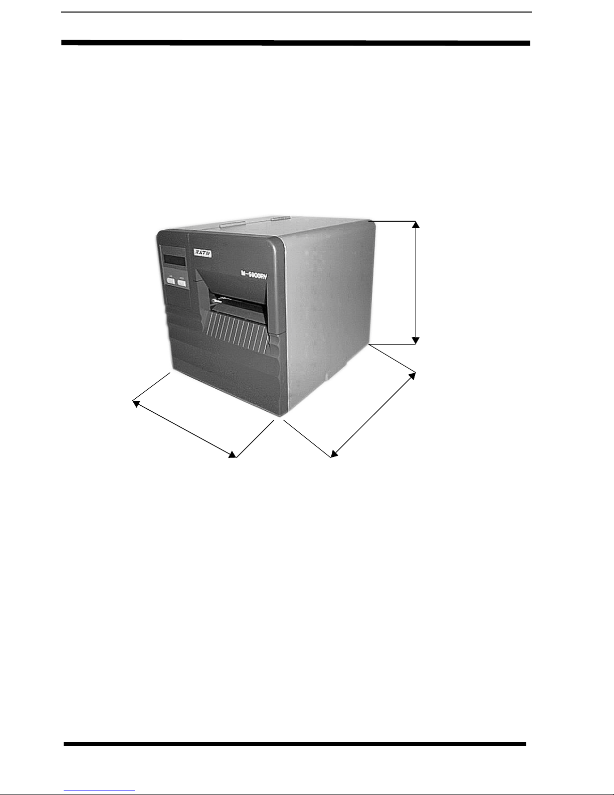
2.2 Dimensions
NOTE: The exact position of components may vary, depend-
ing on the model.
Width 260 mm
Depth 322 mm
Height 280 mm
Width
Depth
Height

Operation Manual 2. Introduction
M5900RV 13
2.3 Component Designations
Label Guide
Label Unwind
Label Guide
Bracket
Operation
Panel and
Display
Print Head
Assambly
Stepping Motor
Label Guide Shaft
Head Latch
Label Guide
Print Head
Platen
Roller
14 M5900RV
2. Introduction Operation Manual
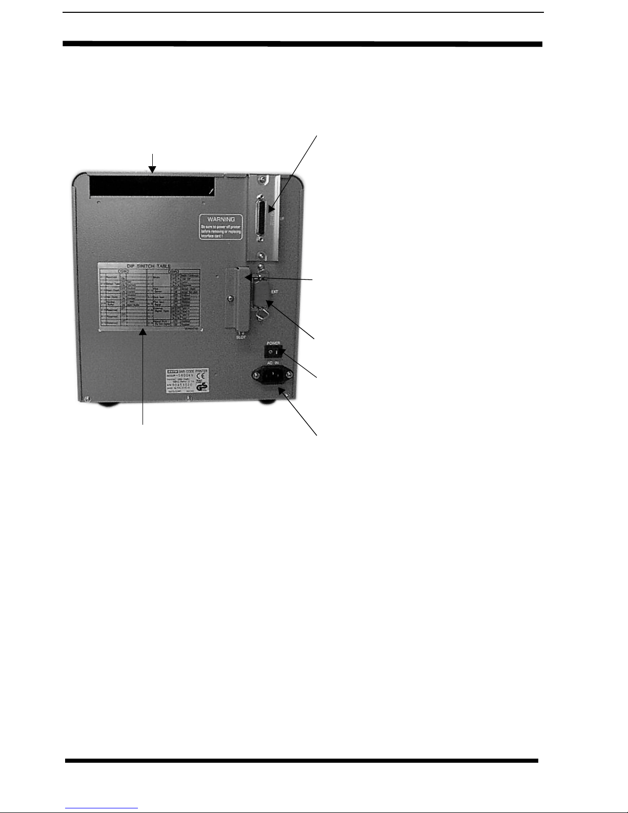
2.4 Rear Panel
Boards are supplied with the following
connectors:
CENTRONICS CONNECTOR:
For printer using parallel communication
connection or
RS232 CONNECTOR:
For printer using serial communication
connection or
TWINAX/COAX CONNECTOR:
For printer operating in a mini/mainframe
computer environment.
MEMORY CARD SLOT 1 & 2:
Optional connectors for use with PCMCIA
Memory Cards.
EXT. CONNECTOR:
This is an external signal connector.
POWER ON/OFF SWITCH:
To turn power On or Off
AC INPUT CONNECTOR:
To input 220V 50/60 Hz. Use power
cable provided.
Fan-Fold Opening
DIP Switch Table
Operation Manual 2. Introduction
M5900RV 15
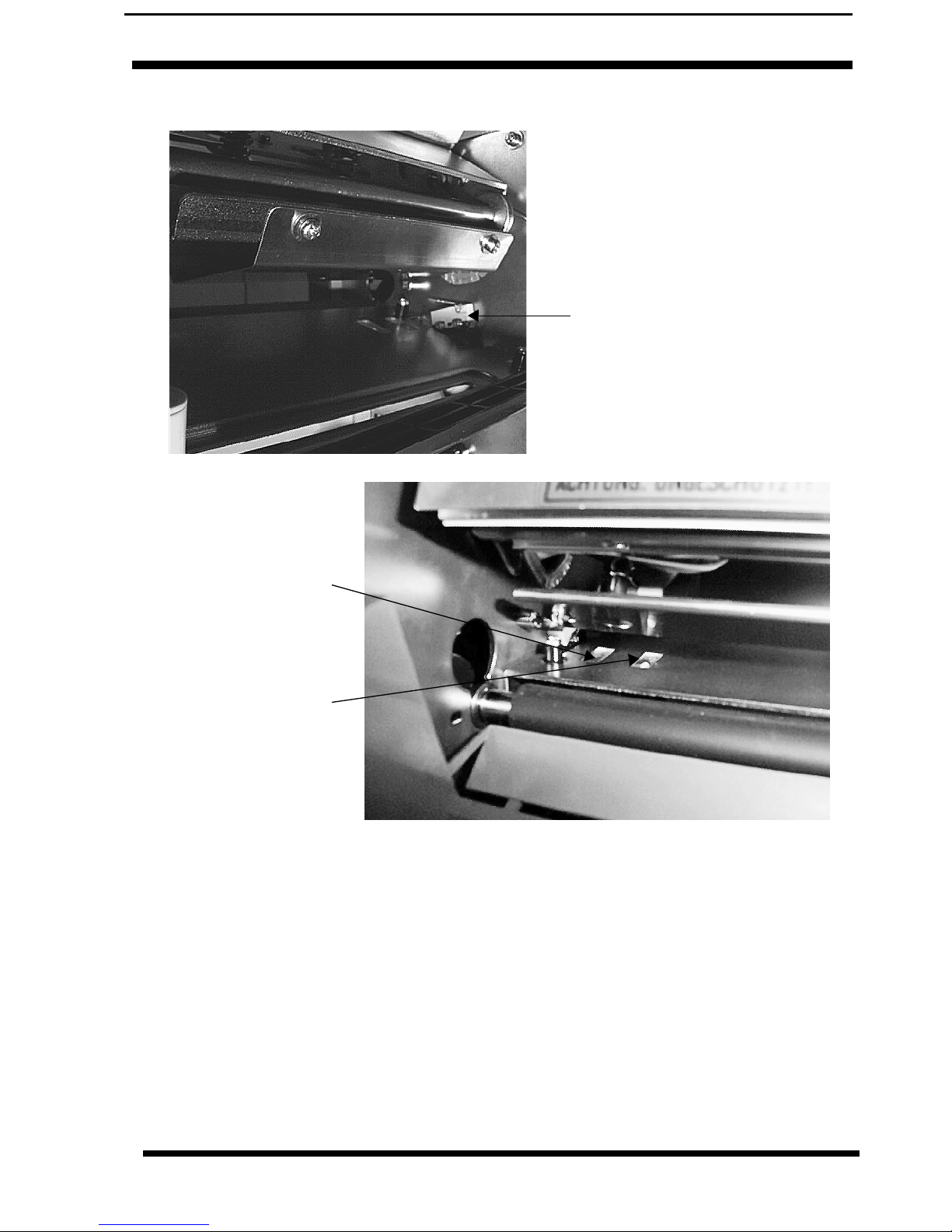
2.5 Switches And Sensors
Head Open Switch.
When the print head is
opened, this switch is
activated and the printer
will stop printing.
I-Mark Sensor
Gap Sensor
(reflective)
(transmissive)

16 M5900RV
2. Introduction Operation Manual
2.6 Operation Panel
FEED Key: Momentary switch.
Pressing this key feeds one blank
label through the printer when it is
off-line. When the printer is on-line,
another copy of the last label will be
printed.
LINE Key: Momentary switch.
Pressing this key toggles the printer
between the on-line and off-line
mode. When the printer is on-line, it is
ready to receive data from the host.
This key acts as a pause during a
print job by taking the printer off-line.
It can also be used as a pause
function key to stop the printer during
the printing process.
PITCH Potentiometer:
Adjusts home position of
the label(+/- 3.75mm).
Affects stop position of
label feed, print position,
and dispense position.
Larger adjustments
should be made using the
Pitch Offset function.
OFFSET Potentiometer:
To adjust back/forward
feed for dispenser
(+/- 3.75mm).
PRINT Potentiometer:
To adjust print darkness
(fine adjustment).
DSW2 & 3: DIP Switches to set operational
parameters of printer.
NOTE: Optional RS232 Communication Card
contains DSW1 switches which are configured
when supplied with the printer.

Operation Manual 3. Configuration
M5900RV 17
3. Printer Configuration
3.1 DIP Switch Settings
Two DIP switches DSW2 and DSW3 are located under the front
door panel and a DSW1 switch is located on an optional RS232
serial interface board.
These switches can be used to set:
•RS232C transmit/receive parameters
•Label sensor enable/disable
•Head check mode
•Hex dump mode
•Receive buffer size
•Operation mode
To set the switches, first power the unit Off, then position the DIP
switches. After placing the switches in the desired positions, power
the printer back on. The switch settings are read by the printer
electronics during the power up sequence. They will not become
effective until the power is cycled.
DIP Switch Panel Layout for DSW1
Located on RS232 Interface Board

18 M5900RV
3. Configuration Operation Manual
3.1.1 RS232 Transmit/Receive Setting
Data Bit Selection (DSW1-1)
This switch sets the printer to receive either 7 or 8 bit data bits for
each byte transmitted.
Parity Selection (DS1-2, DS1-3)
These switches select the type of parity used for error detection.
Stop Bit Selection (DS1-4)
Selects the number of stop bits to end each byte.
Baud Rate Selection (DS1-5, DS1-6)
Selects the data rate(bps) for the RS232 port.
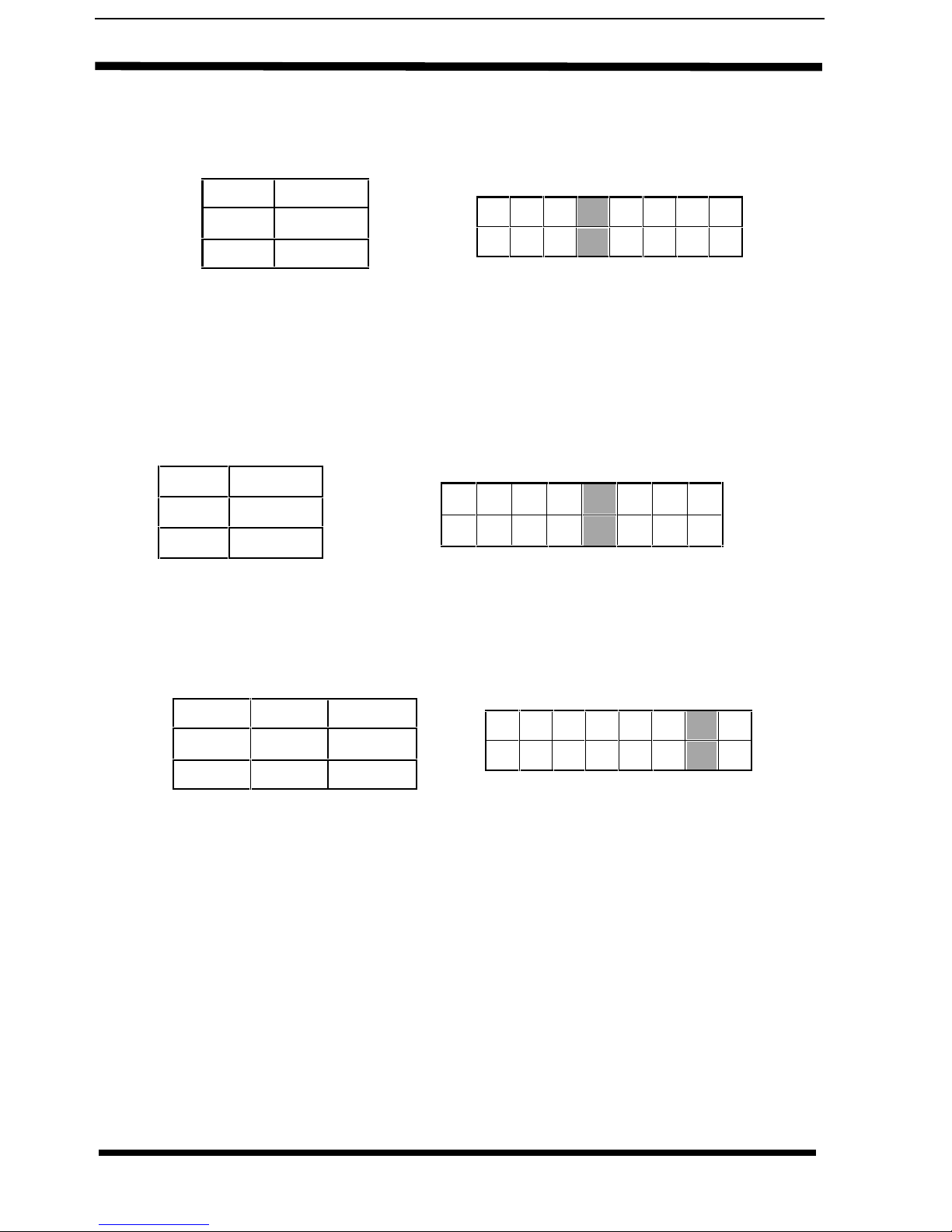
* Factory Default
DSW1-1 SETTING
*OFF 8 Data Bits
ON 7 Data Bits
12 345678
ON
OFF
DSW1
12 345678
ON
OFF
DSW1
DSW1-2 DSW1-3 SETTING
*OFF *OFF No Parity
OFF ON Even
ON OFF Odd
ON ON Not Used
DSW1-4 SETTING
*OFF 1 Stop Bit
ON 2 Stop Bits 12 345678
ON
OFF
DSW1
DSW1-5 DSW1-6 SETTING
*OFF *OFF 9600
OFF ON 19200
ON OFF 4800
ON ON 2400
12 345678
ON
OFF
DSW1

Operation Manual 3. Configuration
M5900RV 19
Communication Protocol Selection (DS1-7, DS1-8)
Selects the flow control and status reporting.
*DS2-1 reserved
Sensor Type Selection (DS2-2)
Selects type of sensing.
Head Check Selection (DS2-3)
When selected, the printer will check for head elements that are
electrically malfunctioned.
* Factory Default
DSW1-7 DSW1-8 SETTING
*OFF *OFF Rdy/Bsy
OFF ON Xon/XOff
ON OFF Bi-Com
ON ON Not Used
DSW1
ON
OFF 12 3 4 5 6 78
DSW2-2 SETTING
*OFF Gap
ON “I”Mark 12 345678
ON
OFF
DSW2
ON
OFF
DSW2
12 345678
DSW2-4 SETTING
*OFF Disabled
ON Enabled
20 M5900RV
3. Configuration Operation Manual
Hex Dump Selection (DS2-4)
Selects Hex Dump mode.
Receive Buffer Selection (DS2-5)
Selects the operating mode of the receive buffer.
Note: The Centronics interface operates only in the multi
job buffer mode regardless of the switch setting.
Protocol Control Code Selection (DS2-6 & DS2-7)
Selects the command codes used for protocol control.
* Factory Default
DSW2-3 SETTING
*OFF Disabled
ON Enabled
DSW2
ON
OFF 12 345678
DSW2-5 SETTING
OFF Single Job
ON Multi Job 12 3 4 5 6 78
ON
OFF
DSW2
DSW2-6- DSW2-7 SETTING
Reserved *OFF Standard
Reserved ON Non - Std. 12 345678
ON
OFF
DSW2
Other manuals for M-5900RV
4
Table of contents
Other SATO Printer manuals


SATO
SATO CT 400 Use and care manual

SATO
SATO LC400e Series Owner's manual

SATO
SATO CL608 User manual

SATO
SATO CT 400 User manual

SATO
SATO /gt Series User manual

SATO
SATO CL4NX Plus User manual

SATO
SATO CX200 Operating instructions

SATO
SATO M8460S User manual

SATO
SATO TG3 Series User manual

SATO
SATO MB 200i User manual


