SATO DR308e User manual

For printer model:
Operator Manual
DR308e
Read this Operator Manual before and during usage of the above product.
Keep this document handy for future reference.
STATUS
LINE
FEE D

NOTE: This equipment has been tested and found to comply with the limits for a Class B digital
device, pursuant to part 15 of the FCC Rules. These limits are designed to provide reasonable
protection against harmful interference in a residential installation. This equipment generates, uses
and can radiate radio frequency energy and, if not installed and used in accordance with the
instructions, may cause harmful interference to radio communications. However, there is no
guarantee that interference will not occur in a particular installation. If this equipment does cause
harmful interference to radio or television reception, which can be determined by turning the
equipment off and on, the user is encouraged to try to correct the interference by one or more of the
following measures:
• Reorient or relocate the receiving antenna.
• Increase the separation between the equipment and receiver.
• Connect the equipment into an outlet on a circuit different from that to which the receiver is
connected.
• Consult the dealer or an experienced radio/ TV technician for help.
Be sure to ask your dealer about our maintenance contracts to
ensure a peace of mind during your usage of SATO products.
Please refer to the back cover for SATO Group Member Company
closest to your location. You may also visit our home page at
www.satoworldwide.com for further updated details.
All rights reserved. No part of this document may be reproduced or issued to third parties in any
form whatsoever without the express permission of SATO. The materials in this document are
provided for general information and are subject to change without notice. SATO assumes no
responsibilities for any errors that may appear.
Version: SI-DR308e-01rA-14-07-08OM
© Copyright 2008
SATO International Pte Ltd

Safety Precautions
DR308e Operator’s Manual Page i
Please read the following information carefully before installing and using the printer.
The Warning symbol
Whenever the triangular Warning symbol appears in this manual, pay special attention to the warning(s) cited
below it. Failure to abide by the warnings may create the danger of death or serious personal injury.
The Caution symbol
Whenever the triangular Caution symbol appears in this manual, pay special attention to the warning(s) cited
below it. Failure to abide by the warnings may result in injury or damage to property.
On Power Supply
Safety Precautions
• Do not use any other voltage except
the specified power voltage for the
printer that matches your domestic
power supply. Otherwise, it may
cause fires or electric shocks.
• Do not damage, break, or process the power
cable. Avoid placing heavy objects on, heating or
pulling the power cable. This may damage the
power cable and cause fires or electric shocks.
• When the power cable is damaged (cable conduc-
tors are exposed or cut, etc.), contact a sales out-
let, dealer, or service center. In this case,
continued use of the printer may cause fires or
electric shocks.
• Do not process, forcibly bend, twist, or pull the
power cable. Continued use of such a cable may
cause fires or electric shocks.
• If the printer emits any smoke or peculiar odors at
any time, stop using the printer immediately. Turn
off the power immediately, disconnect the power
cable from the power outlet, and contact a sales
outlet, dealer, or service center.
• Do not operate the power switch or handle the
power cable with a wet hand. Otherwise, it may
cause electric shocks.
• To reduce electrical risks, be sure
to connect the printer to ground
before use. Also, try not to share
the printer’s AC outlet with other
electrical equipment, especially
those that draw high amounts of
current or cause electrical interference.
STATUS
LINEFEED
STATUS
LINEFEED
Ground
• Place the printer on a solid, stable,
horizontal surface that is not sub-
ject to strong vibrations from adja-
cent mechanical devices. This
may cause malfunction and
shorten the life span of the printer.
• Avoid shaky or slanting tables, or
platforms that are liable to col-
lapse under a heavy weight. If the
printer is dropped or damaged,
immediately turn off the power,
pull out the power plug and con-
tact a service center. In this case, continued use of
the printer may cause a fire or electric shocks.
• Avoid installing the printer in direct
sunlight, or in dusty, very hot or
slippery areas. Also avoid place-
ment in damp, unventilated or
humid areas. If condensation
forms, immediately turn off the
power, and do not use the printer until the conden-
sation disappears. Otherwise the moisture may
cause electric shocks.
• Avoid placing the printer near large high-current
equipment, as such equipment can cause spikes
or under-voltages in the power supply.
LINEFEED
STATUS
LINEFEED
STA
TUS
LINEFEED
On Installation

Safety Precautions
Page ii DR308e Operator’s Manual
• Do not leave containers of liquid or chemicals
around the printer. If any liquid is spilled onto the
printer, immediately turn off the power, pull out the
power cable from the AC outlet, and contact a
sales outlet, dealer, or service center. In this case,
continued use of the printer may cause fires or
electric shocks.
• Do not insert or drop anything metallic or flamma-
ble into the openings of the printer (the cable out-
let). Otherwise, immediately turn off the power,
disconnect the power cable from the power outlet,
and contact a sales outlet, dealer, or service cen-
ter. In this case, continued use of the printer may
cause fires or electric shocks.
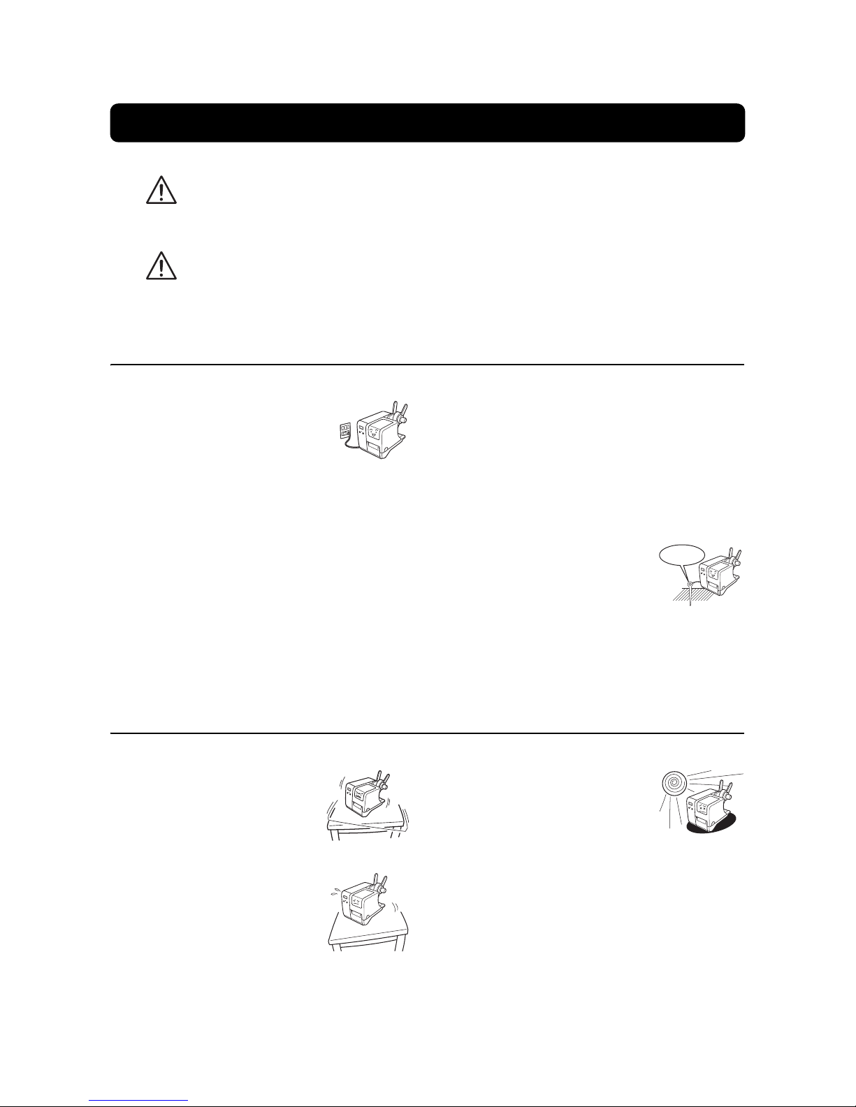
• When moving the printer, be sure to pull out the
power cable from the AC outlet, and check that
any other external interface cables have been dis-
connected. Otherwise, the connected cables may
be damaged, or may cause trips and falls, in addi-
tion to or a fire or electric shocks.
• This printer has a built-in optical sensor. Expose to
strong lighting will make the sensor less respon-
sive and may cause the label to be sensed incor-
rectly. Close the cover when printing.
• The optional head cleaning liquid is flammable.
Never heat it or throw it into a fire. Keep it out of
children’s reach to avoid accidental consumption.
Should this occur, consult a doctor immediately.
• When opening or closing the cover, beware of get-
ting your fingers caught. Also, hold the opening/
closing cover well so that it will not slip and fall on
your hand.
• After printing, the print head remains hot. When
replacing paper or cleaning the printer immedi-
ately after printing, be careful not to burn yourself.
• Touching even the edge of the printer head may
cause injuries. When replacing paper or cleaning
the printer, be careful not to hurt yourself.
• If the printer will not be used for extended periods
of time, disconnect the power cable for safety.
• When releasing and locking down the printer head,
be careful not to catch any other foreign matter in
it except loaded media.
• Do not disassemble or perform modifications to
the printer, as this renders the product unsafe. For
maintenance, troubleshooting and repairs, consult
a sales outlet, dealer, or service center for help,
instead of attempting to perform this yourself.
Renewable annual service contracts are available.
• When maintaining or cleaning the printer, always
disconnect the power cable for safety.
• Do not insert your hand or other objects into the
cutter when the option cutter is installed.
• When loading roll media, be careful not to catch
your fingers between the media and the feeder.
On Installation (cont’d)
On General Handling

Table of Contents
DR308e Operator’s Manual Page iii
TABLE OF CONTENTS
1 Introduction
1.1 Unpacking ..............................................................................................................1-2
1.2 Parts Identification .................................................................................................1-3
2 Installation
2.1 Site Location ..........................................................................................................2-2
2.2 Media Selection .....................................................................................................2-2
2.3 Loading Labels or Tags ........................................................................................2-3
2.4 Loading the Carbon Ribbon .................................................................................3-7
2.5 Remove the Carbon Ribbon .................................................................................3-9
2.6 Adjusting the Pitch Sensor ..................................................................................2-9
2.7 Connections ...........................................................................................................2-10
3 Operation and Configuration
3.1 Operation Panel .....................................................................................................3-2
3.2 Operating Modes ...................................................................................................3-3
3.3 ONLINE And OFFLINE Modes ..............................................................................3-5
3.4 Printer Setting Modes ...........................................................................................3-6
3.5 Paper (media) Mode ..............................................................................................3-6
3.6 User Mode ..............................................................................................................3-7
3.7 Interface Mode .......................................................................................................3-11
3.8 Advance Mode .......................................................................................................3-15
3.9 HEX Dump Mode ...................................................................................................3-22
3.10 Test Print Mode .....................................................................................................3-24
3.11 Default Setting Mode .............................................................................................3-26
4 Cleaning and Maintenance
4.1 Cleaning The Print Head, Platen and Rollers .....................................................4-2
4.2 How To Clean The Printer (Cleaning Kit) ............................................................4-2
4.3 How To Clean The Printer (Cleaning Sheet) .......................................................4-3
4.4 Adjusting Print Quality .........................................................................................4-4
5 Troubleshooting
5.1 Error signal troubleshooting ...............................................................................5-2
5.2 Troubleshooting table ...........................................................................................5-4
5.3 Interface troubleshooting .....................................................................................5-5
5.4 Test print troubleshooting ....................................................................................5-6
6 General Specifications
6.1 Printer Basic Specifications .................................................................................6-1
6.2 Optional Accessories Specifications ..................................................................6-5

Table of Contents
Page iv DR308e Operator’s Manual
7 Interface Specifications
7.1 Interface types .......................................................................................................7-1
7.2 RS232C High Speed Serial Interface ...................................................................7-2
7.3 IEEE 1284 Parallel Interface .................................................................................7-6
7.4 Local Area Network (LAN) Ethernet ....................................................................7-8
7.5 Universal Serial Bus (USB) Interface ...................................................................7-9
7.6 External Signal Interface (EXT) ............................................................................7-9
8 Optional Accessories
8.1 Cutter ......................................................................................................................8-1
8.2 Stacker ...................................................................................................................8-2
8.3 Dispenser ...............................................................................................................8-4
8.4 External Rewinding Unit .......................................................................................8-5
8.5 Keypad ...................................................................................................................8-6
8.6 Calendar IC ............................................................................................................8-6
9 Sato Group of Companies ......................................................... Back cover

Section 1: Introduction
DR308e Operator’s Manual Page 1-1
INTRODUCTION
Thank you for your investment in this SATO printer product.
This Operator’s Manual contains basic information about the installation, setup, configuration, operation and
maintenance of the printer.
A total of eight topics are covered herein, and they are organized as follows:
Section 1: Introduction
Section 2: Installation
Section 3: Operation and Configuration
Section 4: Cleaning and Maintenance
Section 5: Troubleshooting
Section 6: General Specifications
Section 7: Interface Specifications
Section 8: Optional Accessories
It is recommended that you become familiar with each section before installing and maintaining the printer.
Refer to the Table Of Contents at the front of this manual to search for the relevant information needed. All
page numbers in this manual consist of a section number followed by the page number within the stated
section.
For specialized programming, refer to the separate Programming Manual.
This section assists you in unpacking the printer from the shipping container. You will also be guided through
a familiarization tour of the main parts and controls.
The following information is provided herein:
• Unpacking
• Parts Identification

Section 1: Introduction
Page 1-2 DR308e Operator’s Manual
1.1 UNPACKING
When unpacking the printer, take note of the following:
1. The box should stay right-side up.
Lift the printer out of the box carefully.
2. Remove all the packaging covering from the printer.
3. Remove the accessory items from their protective containers.
4. Set the printer on a solid, flat surface. Inspect the shipping container and printer for any sign of damage
that may have occurred during shipping.
Notes
• If the printer was been stored in the cold, allow it to reach room temperature before turning it on.
• Please do not discard the original packaging box and cushioning material after installing the printer. They
may be needed in future, if the printer needs to be shipped for repairs.
1.1.1 Included Accessories
After unpacking the printer, verify that the following materials are in the accessories or packaging:
kciuQ
ediuG
User Documentations
(Quick Guide, Warranty, etc.)
Head cleaning sheet Power cable*
Ferrite core (for attaching
to power cable)
Ribbon core (for winding) Extension guide plates,
core adaptor, screw to
secure the core adaptor
* The shape of the power plug may varied depending on the location of purchased.

Section 1: Introduction
DR308e Operator’s Manual Page 1-3
1.2 PARTS IDENTIFICATION
1 Main Cover
Front View of DR308e
2 Display panel
3STATUS (LED) indicator
4 LINE button
5 FEED button
6 Media ejection slot
8 Cover for potentiometer
and Dip switch compart-
ment
7 Optional device
compartment
Main cover
Open and close this cover to load the media
and ribbon.
Display panel
Displays an error and operation messages.
STATUS (LED)
Lights or flashes to indicate the printer status.
It turns red when error occurred, turns green
when printing and data communication are
enabled (ONLINE) and turns off when the
printer is in OFFLINE mode.
LINE button
Used to start or stop printing, and also to
toggle between the on/off settings for data
transmission and reception.
When the printer is in configuration setting
mode, it is pressed to select options or adjust
the settings.
FEED button
Press once to feed one blank label.
When the printer is in configuration setting
mode, it is pressed to enters to the selected
mode.
Media ejection slot
Opening for media output.
Optional device compartment
This printer comes with a tear-off cover. An
optional device can be installed on this
compartment, e.g. dispenser, cutter, stacker or
external rewinding unit.
Cover for potentiometers and Dip switch
compartment
Open the cover to access the potentiometers
and Dip switch for adjustment.
1
2
3
4
5
6
7
8

Section 1: Introduction
Page 1-4 DR308e Operator’s Manual
1.2 PARTS IDENTIFICATION (cont’d)
9 POWER switch
Back View of DR308e
10 FUSE holder
11 AC IN power terminal
13 Interface slot
14 EXT external connector
terminal
12 Keypad connection
terminal
POWER switch
Turns power On(-) or Off(O).
FUSE holder
Used to hold a fuse which protect the printer
from unstable power supply surge.
AC IN power terminal
Supplies power to the printer by inserting the
power cable.
Keypad connection terminal
Used to connect to the optional keypad.
Interface slot (option)
Optional interface slot for connection to a host
PC. An option of RS-232C (High-speed)
interface board, IEEE1284 interface board,
LAN interface board and USB interface board
are available for connection.
External connector terminal
Interface connector for external signals.
9
10
11
12
13
14

Section 1: Introduction
DR308e Operator’s Manual Page 1-5
1.2 PARTS IDENTIFICATION (cont’d)
18 Ribbon supply spindle
Side View of DR308e with main cover open
17 Roll media guide
25 Media guide shaft
22 Platen roller
15 Supplied yellow
screwdriver
19 Ribbon take-up spindle
20 Head lock lever
23 Pitch sensor
24 Pitch sensor guide
16 Roll media supply spindle
21 Print head
Supplied yellow screwdriver
Used to adjust the potentiometers and Dip
switches.
Roll media supply spindle
Used to load the roll media, tag or label.
Roll media guide
Set to meet the size of the media used.
Ribbon supply spindle
Used to load the ribbon.
Ribbon take-up spindle
Used to wind up the used ribbon.
Head lock lever
Used to open and close the print head.
Print head
This component is used to print on the paper.
Perform maintenance at regular intervals.
Platen roller
This roller feeds the paper. Perform
maintenance at regular intervals.
Pitch sensor
Detects the holes in the tag stock so that the
media can be cut off by the cutter.
Pitch sensor guide
Adjustment slide used to align the position of
the pitch sensor with the holes.
Media guide shaft
Set to meet the size of the media used.
15
16
17
18
19
20
21
22
23
24
25

Section 1: Introduction
Page 1-6 DR308e Operator’s Manual
1.2 PARTS IDENTIFICATION (cont’d)
26 CHECK connector
Adjustment compartment at the right bottom side of DR308e
27 DISP potentiometer
31 PRINT
potentiometer
28 F-OFFSET potentiometer
29 J-HOLE potentiometer
30 IM potentiometer
32 OFFSET potentiometer
33 PITCH potentiometer
34 DSW dip switch
35 GAP potentiometer
CHECK connector
This is a connection terminal for sensor level
adjustment jig.This is only used by Sato
certified servicing personnel.
DISP potentiometer
To adjust the sensing level of the optional
dispenser.
F-OFFSET potentiometer
Factory offset adjustment. Adjust only when
instructed by Sato certified servicing
personnel.
J-HOLE potentiometer
Jump hole sensor adjustment.
IM potentiometer
I-mark sensor adjustment.
PRINT potentiometer
To adjust the darkness of the printing.
OFFSET potentiometer
To adjust the option stop positions (cutter
position, dispensing position and tear-off
position).
PITCH potentiometer
To adjust the beginning print position.
DSW dip switch
To set the printer to different modes when
servicing. This is only used by Sato certified
servicing personnel.
GAP potentiometer
Gap sensor adjustment.
15
26
16
27
17
28
18
29
19
30
20
31
21
32
22
33
23
34
24
35

Section 2: Installation
DR308e Operator’s Manual Page 2-1
INSTALLATION
This section assists you in installing consumable media to the printer, as well as adjustment instructions and
installing other optional attachment units.
The following information is provided:
• 2.1 Site Location
• 2.2 Media Selection
• 2.3 Loading Labels or Tags
• 2.4 Loading the Carbon Ribbon
• 2.5 Remove the Carbon Ribbon
• 2.6 Adjusting the Pitch Sensor
• 2.7 Connections

Section 2: Installation
Page 2-2 DR308e Operator’s Manual
2.1 SITE LOCATION
Consider the following when setting up the printer:
• Place the printer on a solid flat surface with adequate room. Make sure there is enough room at the
top and right-hand (facing the printer) side to provide clearance for the label access door to swing
open.
• Place it away from hazardous materials or dusty environments.
• Place it within operational distance of the host computer, within interface cable specifications
2.2 MEDIA SELECTION
The size and type of the labels or tags to be printed should have been taken into consideration before printer
purchase. Ideally, the media width will be equal to, or just narrower than, the print head. Using media that
does not cover the print head will allow the platen roller to tread on it and wear it out. The media edge will also
wear a groove in the platen roller affecting print quality.
Note:
For optimal print performance and durability, please use SATO-certified label and ribbon supplies
on this printer. Using supplies not tested and approved for use by SATO can result in unnecessary
wear and damage to vital parts of the printer, and may void the warranty.
This printer can use five different types of media: three types of tag stock and two types of label media.
The methods used for loading tag stock and label media differ.
Tag stock
Center-hole
tag
Front side
Hole
Side-hole
tag
l-mark tag
Front side
Hole
Front side
l-mark
Reverse side
Front side
Front side
Fold perforation
I-mark
Reverse side
Label gap
Label
I-mark
1.5 mm
Label
3 mm
Gap (spacing)
3 mm
Gap (spacing)
Paper feed direction

Section 2: Installation
DR308e Operator’s Manual Page 2-3
2.2 MEDIA SELECTION (cont’d)
This printer accepts two types of media core sizes, φ40mm (1.5in.) and φ100mm (4in.). When using φ100mm
(4in.) core size media, the supplied core adaptor and guide plates need to be installed to the printer. Please
refer to Section 2.3.2 Loading Roll media with a large media core on page 2-5 for further instructions.
2.3 LOADING LABELS OR TAGS
2.3.1 Loading Roll media with small media core
1. With the power supply is off, lift up the main cover.
Make sure that the cover rests firmly so that it will not fall
forward and injure your hands.
2. Remove the roll media guide by pressing the release
tab with your thumb and index finger and pulling it out.
3. Load the media to the roll media supply spindle.
Make sure the media leader is pull out from the bottom
and the printed side is facing upwards. Push the roll
firmly towards the end of the spindle.
φ 40mm (1.5”)
φ100mm (4”)
Main cover
Printed
side
should
face
upwards

Section 2: Installation
Page 2-4 DR308e Operator’s Manual
2.3 LOADING LABELS OR TAGS (cont’d)
4. Attach the roll media guide back and make sure that
the roll media guide pushes snugly against the media
roll to prevent media drift during printing.
5. Release the purple head lock lever by turning counter
clockwise.
The print head assembly will be lifted up to allow media
loading.
6. Insert the media into the media guide from a sideways
angle, so that the media passes underneath the media
guide shaft and pitch sensor guide.
Inspect the media routing and verify that the path
matches that illustrated on the inner side of the main
cover.
7. Lightly push the entire media against the media guide
designated position. Adjust the sliding guide until it
lightly touches the edge of the label.
8. Now remount the print head by turning the head lock
lever clockwise until it latch on. The print head should
lock into place firmly.
9. After loading the media and the carbon ribbon, close the
main cover and do a test print to check that the media
roll has been loaded properly. See Section 3.10 Test
Print Mode on page3-24 for instructions on how to run
test print.
Notes:
• Be careful not to get your fingers caught at the bottom
ledge when you are closing the main cover.
• If the optional cutter or dispenser has been pur-
chased, see Section 8 Optional Accessories on
page 8-1 on how to route the media.
Caution
• When replacing media, bear in mind that the print head and its surrounding area remain hot. Keep
your fingers away from these areas to prevent injury.
• Avoid touching even the edge of the print head with your bare hands.
Head lock
lever
(purple)
Media guide shaft
Pitch sensor
guide Sliding guide
Head lock
lever
(purple)

Section 2: Installation
DR308e Operator’s Manual Page 2-5
2.3 LOADING LABELS OR TAGS (cont’d)
2.3.2 Loading Roll media with a large media core
1. With the power supply is off, lift up the main cover.
Make sure that the cover rests firmly so that it will not fall
forward and injure your hands.
2. Remove the roll media guide by pressing the release
tab with your thumb and index finger and pulling it out.
3. Unfasten the screw holding the roll media supply spin-
dle. Use a flat-blade screwdriver to unfasten the screw.
4. Rotate the spindle to 90 degree in the upper right (coun-
ter clockwise) direction.
5. Fasten the screw that you unfastened in step 3.
Main cover
Roll media
guide

Section 2: Installation
Page 2-6 DR308e Operator’s Manual
2.3 LOADING LABELS OR TAGS (cont’d)
6. Attached a supplied extension guide plate to the side
of the roll media supply spindle. Attached the other
two extension guide plate to the roll media guide.
7. Insert the supplied core adaptor to the roll media
supply spindle. Align the screw hole of the core adap-
tor with the specific screw hole on the supply spindle
according to the width of media used as stated in the
table below.
8. Fasten the core adaptor in place with the supplied
screw.
9. Load the media.
Follow the instructions of Section 2.3.1 Loading Roll
media with small media core from step 3 onwards.
Caution
• When replacing media, bear in mind that the print
head and its surrounding area remain hot. Keep your
fingers away from these areas to prevent injury.
• Avoid touching even the edge of the print head with
your bare hands.
Core adaptor attachment
position Media width
Attachment hole 1 Up to 50 mm (2in.)
Attachment hole 2 50 mm (2in.)to 80 mm (3in.)
Attachment hole 3 Not used
2
31
Core
adaptor
Roll
media
supply
spindle

Section 2: Installation
DR308e Operator’s Manual Page 2-7
2.4 LOADING THE CARBON RIBBON
This printer enable two types of printing application, Thermal transfer and Direct thermal. Thermal transfer
paper media requires the use of carbon ribbon for print application. In such a scenario, it is the carbon ribbon
that contains the ink that will be transferred to the media. Direct thermal paper media has a coating on the
surface that is made visible through the application of heat from the print head. In this case, there is no need
of loading the carbon ribbon.
1. With the power supply is off, lift up the main cover.
Make sure that the cover rests firmly so that it will not fall
forward and injure your hands.
2. Release the purple head lock lever by turning counter
clockwise.
The print head assembly will be lifted up.
3. Open the carbon ribbon package, and then load the
ribbon on the ribbon supply spindle.
Push it inwards all the way, with the ribbon winding in a
counter-clockwise direction. The dull side of the ribbon
should be facing down as it travels through the print
head assembly.
Note:
Use only genuine SATO carbon ribbons for maximum
print quality and printer durability.
4. Mount the empty ribbon core on the ribbon take-up
spindle.
When loading the carbon ribbon for the first time, an
empty ribbon core is supplied with the printer. However,
the subsequent ribbon core can be obtained from the
last used up ribbon roll.
Main cover
Purple head
head lever

Section 2: Installation
Page 2-8 DR308e Operator’s Manual
2.4 LOADING THE CARBON RIBBON (cont’d)
5. From the ribbon supply spindle, pass the carbon
ribbon underneath the print head assembly to the
ribbon take-up spindle. Route the ribbon behind and
over the top of the ribbon take-up spindle and tape the
leader portion of the carbon ribbon to the ribbon core.
Then turn the take-up spindle several times in the
direction of counter-clockwise to wind the ribbon around
the core. Confirm that the ribbon has been loaded as
shown in the figure on the right or as illustrated on the
inner side of the main cover.
Note:
Do not pass the carbon ribbon underneath the pitch sen-
sor unit.
6. Now remount the print head by turning the head lock
lever clockwise until it latch on. The print head should
lock into place firmly.
7. After loading the media and the carbon ribbon, close the
main cover and do a test print to check that the media
roll has been loaded properly. See Section 3.10 Test
Print Mode on page3-24 for instructions on how to run
test print.
Caution
• When replacing carbon ribbon, bear in mind that the print head and its surrounding area remain hot.
Keep your fingers away from these areas to prevent injury.
• Avoid touching even the edge of the print head with your bare hands.
Media
Ribbon
Print head
assembly
Pitch
sensor
Tape
Figure showing carbon ribbon and media path
Head lock
lever
Main
cover
Other manuals for DR308e
1
Table of contents
Other SATO Printer manuals

SATO
SATO CG208 DT/TT User manual

SATO
SATO M-8400RVe Series User manual

SATO
SATO CX400 User manual

SATO
SATO Argox I4 Series User manual

SATO
SATO GT400 series User manual

SATO
SATO HT200e User manual

SATO
SATO Argox D4-250 User manual

SATO
SATO CL608e User manual

SATO
SATO ARGOX CP-EX Series User manual

SATO
SATO M8485S User manual