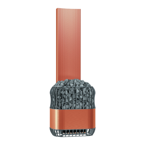
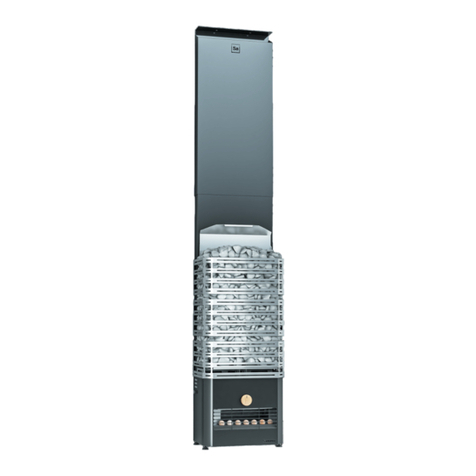
Saunum BASE Operation manual

Sauna climate unit
Saunum BASE / BASE Short / BASE S
ENG
INSTRUCTIONS FOR USE AND INSTALLATION

3
ENG
Saunum Saunas OÜ
congratulates you
on choosing an innovative
sauna climate unit!
TABLE OF CONTENTS
Safety information ___________________________________
INSTALLATION INSTRUCTIONS
Installation _________________________________________
Dimensions of the Saunum BASE / BASE Short models_________
Saunum BASE / BASE Short model installation distances_______
Components of the Saunum BASE / BASE Short device ________
Saunum BASE S model dimensions_______________________
Saunum BASE S model installation distances________________
Electrical connections _________________________________
INSTRUCTIONS FOR USE
Instructions for use __________________________________
Sauna climate control _________________________________
Using the device _____________________________________
Instructions for using himalayan salt balls __________________
Warnings __________________________________________
Maintenance and repair________________________________
Warranty __________________________________________
Installation report _____________________________________
4
6
7
8
9
14
16
20
24
24
24
25
26
27
28
29
TABLE OF CONTENTS

4 5
ENG ENG
These installation and operating instruc-
tions are intended for the owner or main-
tenance provider of the sauna, as well as
the electrician responsible for installing
the sauna climate unit. After installing the
sauna climate unit, the manual must be
handed over to the owner or the main-
tenance provider. Before using Saunum’s
BASE, BASE Short or BASE S sauna climate
unit, please read the installation and safety
instructions.
The BASE / BASE Short / BASE S sauna
steam room climate unit manufactured by
Saunum Saunas OÜ (hereinafter the De-
vice) may not be taken into use before read-
ing the installation and safety instructions!
The Device is designed for mixing layers
of air in the steam room of the sauna and,
harmonizing the temperatures of the in-
door climate of the sauna and, as an added
function, releasing salt ions into the indoor
air from the Himalayan salt balls included
in the set. The special ventilator in the De-
vice generates air ow that harmonizes the
upper and lower air layers of dierent tem-
peratures in the heated sauna and makes
the steam smooth and even.
NB! It is forbidden to use the sauna
climate unit with the heater above 194
°F if the ceiling is not made of non-
combustible material or if there is no
ceiling protection screen above the
heater!
NB! Do not use the Device for anything
other than the intended purpose!
Make sure you do not have allergies and
contraindications to a saline environment.
Consult a doctor about medical contraindi-
cations.
Saunum Saunas OÜ will not be held liable
for various side eects to the health of the
user of the Device. Using Himalayan salt
balls in the Device is an optional added
function which may be left unused without
any eect on the functioning of the Device
in harmonizing the climate of the steam
room.
In the case of any health concerns, the salt
balls can be removed from the base tray
and the Device can be used for only mixing
the layers of air.
CAUTION! The sauna climate unit may
only be activated for the duration of the
steam bath. The sauna climate unit must be
switched o when heating the sauna and
during breaks between steam baths!
Do not pour water into the housing or ven-
tilation openings of the Device or use the
SAFETY INFORMATION
Device in a room where there is water ow-
ing on the oor or where ammable/explo-
sive gases may leak into the air.
The Device may not be used if any hous-
ing components have been removed and/
or the electrical wiring diagram has been
altered. Children must not be allowed
access to the Device or to play with the
Device. Children may not clean the Device.
The Device must be installed by a person
who is qualied to perform electrical
work. The Device must be connected to
the power grid by using permanent wiring
that is suitable for the ambient tempera-
ture conditions. The connecting terminals
of the Device must be equipped with pro-
tective earthing (PE). The cross-sectional
area of the wire must be at least 1.5 mm2.
The Device must be powered from a power
circuit that is protected with overcurrent
and residual-current devices. Supply volt-
age: 230 V 50/60 Hz Wattage: 75 W.
CAUTION! Before servicing and cleaning
the Device, unplug the Device and wait for
the moving parts of the Device to come to
a complete stop.
CAUTION! The Device housing has sharp
corners and edges against which you may
injure yourself if you are not careful.
SAFETY INFORMATION
CAUTION! The sauna climate unit must be
installed so that the exhaust opening is not
directed towards the heater.
TRANSPORT
AND STORAGE
The Device is packaged by the manufac-
turer in a way that ensures the preservation
of the Device under normal transport condi-
tions. The Device must not be dropped,
tossed or stored under heavy goods. Store
the Device in a dry room that is protected
from weather eects.

6 7
ENG ENG
INSTALLATION INSTRUCTIONS
INSTALLATION
NB! Read the Safety Information before
beginning installation (see pp 4–5)!
The Device is installed on the wall of the
steam room or behind the inner lining (if
the device is integrated into the wall, the
lining boards must be secured to the sheet
metal face of the air duct with weather-
board clamps) (see Figures 1, 1A, 1B, 1C, 1D,
1E and 2, 2A, 2B, 2C and 2D on the following
pages).
The air outlet of may not be obstructed and
sauna users must keep their feet at least 20
in away from the fan.
The discharged air ow must be able to
spread freely throughout the steam room.
Figure 1
Dimensions of the Saunum
BASE / BASE Short models.
SIDE VIEW
FRONT VIEW REAR VIEW
DIMENSIONS OF THE DEVICE
5.5 in
1 in
4.2 in
8.9 in
15.7 in
BASE 84.9 in; BASE Short 74.8 in
BASE 69 in; BASE Short 58.0 in
17.2 in
4.4 in
39.4 in29.3 in
11.8 in
9.8 in
0.3 in
BOTTOM VIEW
7,9 in
0,5 in
Cable opening

8 9
ENG ENG
Figure 1A - Saunum BASE / BASE Short model installation distances.
DEVICE WALL MOUNTED INSIDE OF WALL
Figure 1B - Saunum BASE / BASE Short model installation distances.
WALL-MOUNTED DEVICE
INSTALLATION INSTRUCTIONS
0.5 in distance
from the wall
7.8 in distance
from the wall
CEILING
FLOOR
Safe distance based
on the manufacturer’s
recommendations
4 in minimum distance from the oor
4.1 in
FLOOR
WALL
0.5 in distance
from the wall
7.8 in distance
from the wall
CEILING
FLOOR
4 in minimum distance from the oor
Safe distance based
on the manufacturer’s
recommendations
Safe distance based
on the manufacturer’s
recommendations
Safe distance based
on the manufacturer’s
recommendations

10 11
ENG ENG
Figure 1C - Components of the Saunum BASE / BASE Short device. The Device works most eciently when the
edge of the upper airing vent opening is
adjacent to the ceiling of the steam room
(model with a protective grille). If the De-
vice is not equipped with a protective grille,
the Device should be installed so that the
upper edge remains 3–4 in below the ceil-
ing. The lower edge may not be closer than
4 in to the oor to prevent the water on the
oor from coming into contact with the
electrical wiring of the Device.
The Device is designed for wall mounting
using the hanging strips included in the
set. The wall in the installation spot must
COMPONENTS OF THE DEVICE
ADDITIONAL AIR VALVE
BOTTOM
TRAY
SALT BALLS
SWITCH
AIR DISCHARGE AND GRILLE
GRILLE MOUNTING
BOLT
GLASS FRONT PANEL
be able to carry the weight of at least 77
lb and allow the supplied hanging strips to
be fastened with screws. The hanging strips
are attached to the wall of the steam room,
each with at least two screws. The Device is
then lifted onto the wall so that both the
upper and lower strips slide between the
strips attached to the back of the Device.
Figure 1D - Saunum BASE / BASE Short
model installation.
INSTALLATION INSTRUCTIONS

12 13
ENG ENG
Figure 1E - Recommended instal-
lation of the Saunum BASE / BASE
Short model using a hanging strip.
1. Install the strips supplied with the
Device on the wall. Use anchors if
necessary.
2. Hang the Device on the wall-mounted
strips. Make sure that the eyelets on
the back of the Device rest equally on
both slats. (If necessary, use a spirit
level to ensure that the Device is level.)
3. Check the Device for any external
damage. It is forbidden to use a dam-
aged Device!
4. Install the salt balls. The salt balls are
placed in the Device after it has been
mounted on the wall. To install the balls,
open the lower grille by removing the
two hand-turned bolts. Place the balls in
their slots on the tray.
SALT BALLS
FASTENING BOLT TO REMOVE
COVER GRID
HANGING STRIP
INSTALLATION INSTRUCTIONS
Screws (min 2 pcs)
1000 mm33 in MIN distance from the oor

14 15
ENG ENG
SIDE VIEW
BOTTOM VIEW
FRONT VIEW REAR VIEW
Figure 2
Saunum BASE S model dimensions.
DIMENSIONS OF THE DEVICE
According to the ceiling height
4.4 -6.9 in
8.9 in
4.5 in
45.3 - 74.4 in
66.5 - 90.6 in
16.7 in
29.3 in
0.3 in
11.8 in
9.8 in
7,9 in
0,5 in
Cable opening

16 17
ENG ENG
DEVICE WALL MOUNTED INSIDE OF WALL
Figure 2A - Saunum BASE S model installation distances. Figure 2B - Components of the Saunum BASE S model device.
COMPONENTS OF THE DEVICE
SALT BALLS
ADDITIONAL AIR DAMPER
BOTTOM
TRAY
SWITCH
HANGING STRIP
SHEET METAL FRONT PANEL
GRILLE
INSTALLATION INSTRUCTIONS
0.6 in distance
from the wall
7.9 in distance
from the wall
CEILING
FLOOR
4 in minimum distance from the oor
1.9 in
FLOORWALL
Safe distance based
on the manufacturer’s
recommendations
Safe distance based
on the manufacturer’s
recommendations

18 19
ENG ENG
Figure 2C - Recommended instal-
lation of the Saunum BASE S model
using a hanging strip.
1. Install the strips supplied with the
Device on the wall. Use anchors if
necessary.
2. Hang the Device on the wall-mounted
strips. Make sure that the eyelets on
the back of the Device rest equally on
both slats. (If necessary, use a spirit
level to ensure that the Device is level.)
3. Check the Device for any external
damage. It is forbidden to use a dam-
aged Device!
4. Before using the Device, cover all un-
covered openings using the specied
aluminum tape to do so.
5. Place the salt balls. The salt balls are
placed in the Device after it has been
mounted on the wall. To place the balls,
open the lower grille by removing the
two hand-turned bolts. Place the balls in
their slots on the tray.
HANGING STRIP
INSTALLATION INSTRUCTIONS
Adjust the sides
and top of the cap
Opening under the cap after
adjusting the telescopic cap
Screws (min 2 pcs)
Based on the height of the room!33 in MIN distance from the oor
Fastening bolt to
remove the grille
Salt balls

20 21
ENG ENG
ATTENTION! The Device must be ins-
talled by a person who is qualied to
perform electrical work, in accordance
with the applicable standards and
requirements.
The Device must be permanently connect-
ed to the power grid using a screw terminal
and a cable that is suitable for the tem-
perature conditions in compliance with the
electrical connection diagrams presented
in this manual (Figures 3, 3A, 4, 5 and 6 on
the following pages).
The outer diameter of the cable must
not exceed 0.4 in. The connection termi-
nal of the Device must be equipped with
protective earthing (PE) with a minimum
cross-sectional area of the wire being 1.5
mm2. The Device must be powered by a
230 VAC 50/60 Hz supply circuit which is
protected with a C2 overcurrent protection
device, and the supply circuit of the Device
must also be equipped with a residual cur-
rent device to ensure the safety of people in
the steam room.
The lighting of the Device must be connect-
ed to either an external internal switch. The
power circuit for the external light switch
must also be equipped with residual-
current and overcurrent protection devices.
The lighting and fan circuits of the Device
are connected to external switches, the
supply circuits of which are equipped with
residual-current and overcurrent protec-
tion devices. The power cable must enter
the Device housing vertically from below
N
L
LN
Figure 3 - Connecting the power cable to a
Device equipped with an internal fan speed
switch.
The wiring diagram only applies to an illu-
minated Device with an external switch!
NB! Perform the wiring in accordance with
the instructions provided for in the wiring
diagram of the Device.
NB! The circuit must include residual-
current and overcurrent protection devices!
PEN
L
N
L
NB! Only connect via residual-current and
overcurrent protection devices!
The power cable being used must be de-
signed for stationary electrical installations
and compliant with the requirements for
the electrical installation installed in the
steam room.The cross-section of the power
cable must be 1.5–2.5 mm2.
Insert the power cable through the hole in
the bottom of the Device, in accordance
with the installation instructions.
The power cable must not be left lying on
the oor of the steam room.
Figure 3A – Connecting the power cable
to a Device equipped with an internal fan
speed switch.The main power supply of the
Device.
Figure 4 – Connecting the power cable
to a Device equipped with an external fan
speed switch.
NB! The circuit must include residual-
current device and overcurrent protection
devices!
Fan power supply. NB! The circuit must
include residual-current and overcurrent
protection devices!
NB! Perform the wiring in accordance with
the instructions provided for in the wiring
diagram of the Device.
ELECTRICAL CONNECTIONS
to prevent water from entering the Device
along the cable. The external insulation lay-
er of the cable may only be peeled o in the
section which remains inside the housing
of the Device.
N 2 3 4 PE
GOTTAK 4RH
Red
Brown
Black
Black
White
Green
N L PE
1
3
2
a
4
d

22 23
ENG ENG
Figure 5 –Wiring diagram. Figure 6 – Wiring diagram: Device, equipped with illumination and a switch.
ELECTRICAL CONNECTIONS
POWER SUPPLY FOR THE LIGHTS 120 VAC DEVICE HOUSING
POWER/SPEED
120 VAC FAN POWER INPUT TERMINAL
NB! ONLY CONNECT THROUGH AN AUTOMATIC
PROTECTIVE DEVICE!
~~
N L PE
Black
ACL
ACN
White
Black
Black
Red
Brown
Black
R1
47R
White
Red
Brown
Black
c1 J8
c2
J9
6,3 uF 450VAC
NL L PE 4 3 2
D1 D2
V+
V- L1
GOTTAK 4RH
1
2
3
4
a
d
N
POWER/SPEED
120 VAC FAN POWER INPUT TERMINAL
NB! CONNECTION ONLY PERMITTED THROUGH
AN AUTOMATIC PROTECTIVE DEVICE!
FAN HOUSING
FAN HOUSING
DEVICE HOUSING
DEVICE HOUSING
FAN SAUNUM M001
FAN SAUNUM M001
LED power supply 120 VAC / 12 VDC, 1.5 A
FAN
120V - 50/60Hz 75W
SAUNUM M001
FAN HOUSING
POWER/SPEED
BASE without illuminationBASE S Device, switchless.

24 25
ENG ENG
INSTRUCTIONS FOR USE
The Device is designed for harmonizing the
climate of the steam room during a steam
session.
Before using the Device for the rst
time, check:
• compliance of the wiring with the
requirements
• compliance of the supply voltage
with the rated voltage of the Device
• the condition of the protective
earthing (PE)
• the mountings on the Device hous-
ing
• the wall mountings of the Device
• the condition / presence of overcur-
rent and residual-current protection
devices
• if the fan rotor can rotate freely
• if all tools and residues of the
materials used during installation
are removed from the housing of
the Device
When starting the Device, check:
• the direction of air ow – air must
be drawn from the upper and
blown out from the lower opening;
• for abnormal vibration or noise
when the fan is running;
• the lighting stability for LED
equipped devices.
NB! The ceiling of the steam room must
be made of non-combustible material
or equipped with a shield made of
non-combustible material (27 × 27 in at
minimum).
SAUNA CLIMATE
CONTROL
The volume of air circulated by the Device
can regulated by a rotary switch located on
the lower right side of the Device.
The switch has four positions and can be
turned both clockwise and counter-clock-
wise. When the bar on the switch button
points to the left, the Device’s fan is turned
o. Airow speed increases by turning the
switch clockwise, you can choose between
three dierent speeds.
To control the air temperature in the steam
room, an air-cooling damper for steam is
located on the bottom front panel of the
Device (see Figures 1C and 2B). The recom-
mended setting is to keep the cooling
damper 1/3 open. To cool the steam, try
opening the damper incrementally. Try us-
ing dierent fan speeds to nd the perfect
indoor climate for your sauna.
USING THE DEVICE
The Device is to be switched on immedi-
ately before entering the steam room and
switched o immediately after leaving
the steam room. The Device may not be
switched on when heating the steam room
or when there is no one in the steam room,
as the operation of the Device will increase
the temperature in the lower part of the
steam room and the bench and oor may
become too hot.
To ensure long service life of the Device,
make sure that the temperature in the
steam room at the lower part of the
Device does not exceed 176 °F. If this
temperature is exceeded, the thermal pro-
tection will activate and the fan will stop;
once the temperature falls below the acti-
vation level of the protection, the fan will
be switched on again.
The manufacturer will not be held liable for
equipment failures resulting from exceed-
ing the permitted operating temperature.
If your Device is equipped with internal
lights, the lights will activate at the same
time as the fan (see the marking on the
packaging of the Device) when the Device
is switched on.
If your Device is wall-integrated and
equipped with an external touch-
sensitive switch for speed control,
please keep in mind the following
requirements:
• The external speed switch may
only be installed outside the steam
and washing room, e.g. the chang-
ing room, preferably next to the
door, so that the Device can be
conveniently switch on and o.
• The switch has three positions for
selecting the desired airow inten-
sity. The Device can be switched on
and o by pressing and holding
the touch-sensitive button of the
desired speed.
• Touch the appropriate area to
select speeds.
• If the Device is equipped with
internal lighting, a separate switch
(optional) must be used to switch
it on.
INSTRUCTIONS FOR USING
HIMALAYAN SALT BALLS
The sauna climate unit comes with Hima-
layan salt balls. The use of salt balls in the
Device is optional and does not aect the
basic function of the Device.
To use the salt balls, they must be placed in
the base tray located between the air dis-
charge grille and the fan. Make sure that
the salt balls are placed correctly and do
not impede the rotation of the fan.
To place or remove the salt balls (see
Figures 1D and 2C), loosen the two fasten-
ing bolts on the discharge grille and lower
the grille on its hinges. Do not use excessive
force! After placing or removing the salt
balls, shut the discharge grille and fasten it
with two bolts.
The sauna climate unit may only be used
if the grille is installed!
INSTRUCTIONS FOR USE

26 27
ENG ENG
WARNINGS
• Remaining in the steam room for
an extended period of time raises
your body temperature, which can
be dangerous to your health!
• Do not allow children, disabled or
ill persons in the steam room un-
attended!
• Consult a doctor regarding medical
contraindications to sauna bath-
ing!
• Consult your doctor regarding
medical contraindications to salt
treatment!
• Make sure you are not allergic
to salt treatment. Saunum is not
responsible for the side eects of
salt treatment!
• Consult a pediatrician or family
physician about allowing children
to take a sauna bath!
• Use caution when moving in the
sauna and the steam room, as the
bench and oor can be slippery!
• Do enter the sauna under the
inuence of alcohol, medications
or drugs!
• Do not sleep in a hot steam room!
• Sea air and humid climates may
cause an oxide layer (rust) to form
on the metal surfaces of the heater!
• Make sure you have proper venti-
lation in the steam room. Saunum
is not responsible for possible cor-
rosion damage caused to the sau-
na equipment by salt. If necessary,
consult a specialist!
• Do not hang towels and clothes to
dry in the steam room – this may
cause a re hazard!
• Excessive moisture can damage
electrical equipment!
• Electrical components should not
be, exposed to water.
• Maintenance, and installation,
should be performed in a cool and
dry environment.
NB! Do not leave the fan of the sauna cli-
mate unit running when you are not in
the steam room – doing so will result in
excessive energy consumption and the
bench may become too hot!
MAINTENANCE
AND REPAIR
CAUTION! Before servicing and cleaning
the sauna climate unit, the power circuit of
the Device must be disconnected from the
mains and the moving parts of the device
must come to a complete stop.
Before servicing and cleaning the Device,
make sure that:
• the Device has been disconnected
from the mains (switched o at the
overcurrent protection device in
addition to the power switch of the
Device);
• the Device’s fan has stopped
completely;
• the required occupational safety
and personal protective equip-
ment is used when performing the
works;
• the connecting cables are undam-
aged. If any damage to cables is
detected, the cables must be re-
placed by a qualied electrician
in accordance with the applicable
standards and requirements before
continuing maintenance and
cleaning work.
The Device housing can be cleaned with a
cloth dampened with water.
Do not use a pressure washer or running
water to clean the Device! Do not use
chemical cleaners or solvents to clean
the Device!
Excessive dirt can cause imbalance of the
fan rotor, which increase the noise level
when the Device is operating. Damaged or
bent fan blades may also increase the noise
level. Make sure that no foreign objects en-
ter the operating area of the fan rotor.
Generally, the fan does not need to be
cleaned more than once a year. Only quali-
ed persons may clean the fan.
Using compressed air to clean the fan
may permanently damage the fan rotor!
Fan bearings are maintenance-free and
must be replaced if malfunctions occur.
Make sure that there are no foreign objects
in the air vents of the fan of the sauna cli-
mate unit. The Device is not meant to be
cleaned by children.
If Himalayan salt balls are used with the
sauna climate unit, it is recommended that
the state of wear of the salt balls be checked
once per year (see Figures 1D and 2C).
Whenthediameteroftheballs hasdecreased
by more than a half, the salt balls must be re-
placed. To replace the balls, remove the salt
ball container from the Device and wash
it under running water to remove any salt
residue. Install the container and place new
salt balls in their slots.
In the event of any malfunctions involv-
ing the Device’s fan and lighting, stop
using the Device immediately and have
it inspected by a qualied person.
WARNINGS
MAINTENANCE AND REPAIR

28 29
ENG ENG
GENERAL WARRANTY
CONDITIONS FOR
SAUNUM PRODUCTS
With the Saunum Equipment Warranty,
Saunum guarantees that the product will
be free from materials and manufactur-
ing defects for a specied period after the
date of purchase. In the event of a defect
in the Device during the warranty period
due to the use of low-quality materials or
low quality of assembly, the recommended
repair partners of Saunum will repair or
replace the Device or its defective part
without charging for labor and spare parts
under the conditions presented below. Sau-
num reserves the right to decide whether
to replace the defective product compo-
nent or replace the Device with a new one.
Replaced defective product components
remain the property of Saunum.
Warranty conditions:
1. The warranty is only valid if a com-
pleted installation report is submit-
ted with the claim.
2. A warranty period of two (2) years
applies to the Device if it is used in
a private sauna.
3. A warranty period of one (1) year
applies to the Device if it is used in
a public sauna.
The warranty does not cover:
1. Routine maintenance and cleaning
the Device, and replacing compo-
nents due to normal wear and tear;
2. Adapting or modifying the Device
to use it for purposes other than
those stated in the operating
instructions;
3. Risks associated with transport;
4. Damage caused by misusing the
Device;
5. Damage caused by improper
installation of the Device;
6. Repairs performed by a party
other than a recommended repair
partner (maintenance partner) of
Saunum;
7. Accidents, lightning, water, re,
improper ventilation or any other
factor beyond the control of
Saunum;
8. Faults caused by the use of salt balls
not recommended by Saunum;
9. Salt balls.
The list of installation and maintenance
technicians recommended by Saunum
Saunas OÜ is available on the website of
Saunum Saunas OÜ at www.saunum.com
The maintenance instructions for the device
are given in the user manual of the Device.
NB! The sauna climate unit may only be
connected to the mains by a professional
electrician in accordance with the applicable
regulations.
INSTALLATION REPORT
Purchase date: ___________________________________________________________
Heater type: _____________________________________________________________
Sticker / serial number:
Place of installation: _______________________________________________________
Date of installation: ______________________________________________________
Installed by: ____________________________________________________________
Checked: _______________________________________________________________
Date, signature: __________________________________________________________
Description of work performed: ______________________________________________
All details are available for installation _______________________________________________
No color defects or dents_________________________________________________________
Mounted on the wall or oor according to the instructions________________________________
The electrical connections have been made in accordance with the installation instructions________
The three stages of the fan are running / in the correct order _______________________________
NOTES: ______________________________________________________________
Customer contact (name, e-mail):____________________________________________
Work accepted: __________________________________________________________
Warranty start date: _____________________________________________________
TO BE COMPLETED BY THE CUSTOMER
Read the entire user guide carefully and
thoroughly before using the Device and
keep it in a safe and easily accessible place
for future reference.
WARRANTY
WARRANTY

30 31
ENG ENG
EC Declaration of Conformity
Manufacturer: Saunum Saunas OÜ
Address: Läike tee 2-4
75312 Tallinn, Estonia
certies that the product:
Indoor climate unit in the sauna
steam room
complies with the requirements set forth in the following directives of
the European Council, provided that the installation has been carried out
in accordance with the installation instructions issued by the equipment
manufacturer and the instructions EN 60 204-1 ‘Safety of Machinery. Electrical
Equipment of Machines – Part 1: General Requirements’: Machinery Directive
2006/42/EC; Low Voltage Directive 2014/35/EU; Electromagnetic Compatibility
Directive 2014/30/EU.

ENG
INSTRUCTIONS FOR USE AND INSTALLATION
Sauna climate unit
Saunum BASE / BASE Short / BASE S
This manual suits for next models
2
Table of contents
Other Saunum Heater manuals
Popular Heater manuals by other brands

Frico
Frico RDS Series Original instructions

Warmlite
Warmlite WL41003Y Safety & instruction manual

Procom
Procom PCFA125V owner's manual

Ideal Heating
Ideal Heating Halo installation guide

Harvia
Harvia FU60 Instructions for installation and use

Frico
Frico Elztrip EZ100 Installation and operating instructions