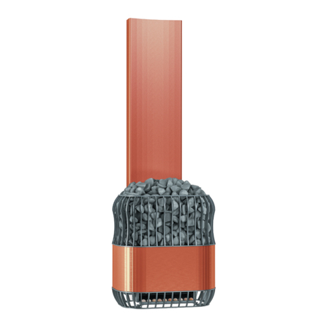
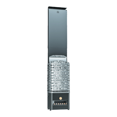
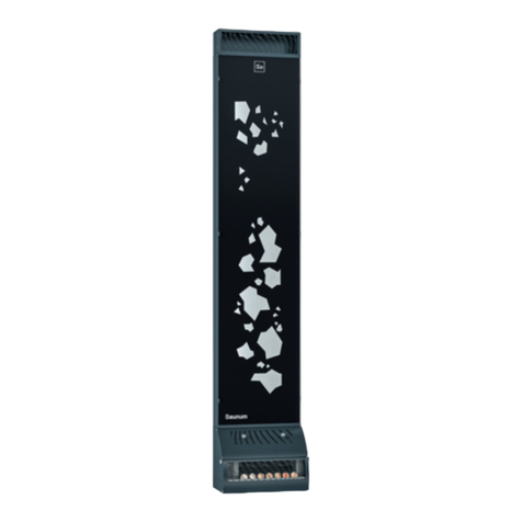
Saunum Spa Session Operation manual

Saunum Spa Session
all in one sauna heater to create a spa atmosphere
INSTRUCTION FOR USE AND INSTALLATION

2
THE BEST SAUNA
EXPERIENCE TO HAVE!
I
am very glad that you have invested in the Saunum
device, and I believe that our innovative technology
will offer you a wonderful and extraordinary sauna
experience.
I have a degree in thermal engineering and come from the
Southern Estonia, where my love for saunas began.The special
feature of local historic smoke saunas is the lower tempera-
ture and higher humidity level than, for example, a classic
Finnish sauna. In ordinary saunas, the stone volume of the
sauna heater is generally small. Such an arrangement can
cause a sudden, burning hot steam and an extremely uneven
temperature, where your head and shoulder level is really hot,
but your feet are left cold. Such an experience can be quite
unpleasant and may cause headaches and lead to body stress.
However, in ancient smoke saunas and Native American sau-
nas, the stones were rst heated during the day.Then the heat
stored in the stones was used to cleanse the body and create a
truly enjoyable sauna experience.
Inspired by the experience of a smoke sauna, I wanted to
create an innovative solution that combines the best features
of an authentic sauna with modern technology; enabling a
pleasantly mild and relaxing sauna experience without pain-
fully scorching steam. For that, however, I had to solve the
problem of how to achieve an even temperature, at both the
head and foot levels. My development work was supported
by research done alongside Tallinn University of Technology,

3
in which we analysed the thermal stratication and air move-
ment in the sauna room. Saunum was born in cooperation
between scientic thinking and technological innovation.
Saunum’s unique patented mixing system of air layers cap-
tures the hot steam that rises under the ceiling of the sauna
room, mixes it with the cooler air from the surface of the oor,
and directs the milder steam back evenly. This makes for an
enjoyable, unaggressive heat. You can sit in the sauna for a
longer time, and enjoy a sweat and a deep cleanse without
feeling tired. The stone volume of our heaters is signicantly
larger than other sauna heaters, which is the reason for the
especially pleasant indoor climate with long and soft steam.
A moist steamy sauna, a therapeutic salt sauna, or a healthy
aroma sauna – all of these functions are available on Saunum’s
devices to create a truly relaxing sauna experience. When
using Himalayan salt balls in our device, salt ions that are
benecial to skin and respiratory tract evaporate and the
steam circulates these into the air. Adding a sauna aroma sys-
tem that blends steam and healthy aroma oil creates an even
more enjoyable sauna environment.
Saunum’s sauna devices are suitable for both adults and
children.
Have a pleasant sauna!
Andrus Vare
The creator of Saunum

Saunum Saunas Ltd
congratulates you
on choosing a heater with
an innovative sauna room
indoor climate device!

5
CONTENTS
Safety information ___________________________________
Safety distances _____________________________________
Dimensions _______________________________________
Product completeness _______________________________
INSTALLING
Before the installation _________________________________
Installation instructions _______________________________
Electrical connections ________________________________
Electric heater insulation resistance ______________________
Installing and replacing the heating elements _______________
INSTRUCTIONS FOR USE
Heating the sauna room ______________________________
Using the sauna climate device _________________________
Adjusting the temperature _____________________________
Regulation of the sauna climate _________________________
Use of Himalayan salt balls ____________________________
Throwing water on the heater ____________________________
Loading the stones ___________________________________
Warnings _________________________________________
Solving problems ____________________________________
Maintenance _______________________________________
Sauna room _________________________________________
Sauna room ventilation _______________________________
Power of the heater __________________________________
Warranty ___________________________________________
Installation Report ____________________________________
6
8
10
11
12
13
16
18
20
22
22
23
23
26
27
28
30
31
33
34
34
34
35
37
CONTENTS

6
SAFETY INFORMATION
SAFETY
INFORMATION
These instructions for installation and use
are intended for the sauna owner or main-
tenance provider, as well as the electrician
responsible for installing the heater with
a sauna room indoor climate device. After
installing the heater with an indoor climate
device, the instructions must be handed
over to the owner or maintenance provider.
Before using the Saunum Spa Session
heater with an indoor climate device (here-
inafter ‘sauna climate device’), read the in-
stallation and safety instructions.
The sauna climate device is intended for
heating the sauna room at 60–90 °C and for
regulating the sauna room climate during
steaming.
NB! The climate control unit and the
heater of the sauna must not be ope-
rated in temperatures exceeding 90 °C!
NB! Do not use the sauna climate device
for any other purposes!
NB! To connect the sauna climate device
to the power network, a control device for
the control of electric heaters is required.
The control device must correspond to
the power of the heater used according to
Table1.
The control device must have the ability to
control the fan of the sauna climate device,
and the function of simultaneously switch-
ing o the heater and the fan of the sauna
climate device is recommended.
Table 1
Power
6 kW
9 kW
3 phase
protection
C10
Power cable mm
3 phase
Device
Saunum Spa Session 190 cm
The minimum height
of the ceiling
190 cm
5 x 2,5
Saunum Spa Session C16 5 x 2,5

7
SAFETY INFORMATION
5–7
7–10
Cubic size of the
sauna room m
Minimum safe distance
from the heater to ceiling
700 mm (height from stones)
To ensure the longevity of the device,
make sure that the temperature of the
sauna room at the height of the lower
part of the device does not exceed 80 °C.
If it is exceeded, the thermal protection will
be applied and the fan will stop; the fan
will start running again if the temperatuure
drops below the fuse limit of application.
The manufacturer is not responsible for any
malfunction caused by an overrun of the
authorized operating temperature.
700 mm (height from stones)
Minimum safe distance
from the heater
A: 50 mm from sides and the front
B: 20 mm from the back side
A: 50 mm from sides and the front
B: 20 mm from the back side

8
SAFETY DISTANCES
Safety distances of the Spa Session sauna
unit and the recommended location in the
sauna room.
Safety distances:
A (minimum distance from sides) 50 mm,
B(minimum distance from back side)
20 mm,
C (minimum distance from side) 50 mm.
SAFETY DISTANCES
Back wall non-combustible material

9
minimum distance from
temperature sensor 300 mm
Air
supply Temperature
sensor
Air
supply
minimum distance from
temperature sensor 300 mm
Air
supply Temperature
sensor
Air
supply
Air
supply
minimum distance from
temperature sensor 300 mm
Air supply
SAFETY DISTANCES
Non-combustile
material
Non-combustile
material

10
205 mm
490 mm
365 mm
1160 mm
Saunum Spa Session
DIMENSIONS

11
PRODUCT COMPLETENESS
A- Front panel
B- Bottom front panel (air outlet grille)
C- Panel covering the electrical connection
D- Side ues
D
A
B
C
G
E
F
E- Stone basket top grille
F- Rear panel
G- Panel covering the controller box
H- Panel covering the electrical motor
H
All parts of the product are supplied in
single package.
Elements required for operation that
are not part of the Spa Session compo-
sition: power supply cables and stones.
Figure 1

12
BEFORE THE
INSTALLATION
The installation of the sauna climate device
must be performed by a qualied electri-
cian. The connection of the device must be
performed in a stable location with a cable
that meets the temperature conditions.
Protective earthing (PE) must be connected
to the connection terminal of the device.
The device must be powered from the con-
trol device’s supply circuit, which is pro-
tected by over-current fuses. The required
over-current fuses sizes and the connection
cables dimensions are given in Table 1 (see
pages 6–7).
All the certied sauna control devices with
the operating capacity corresponding to
the capacity of the Saunum Spa Session
model used in accordance with Table1 (see
pages 6–7) may be used to control the sau-
na climate control device.
Before starting the installation work,
read the installation instructions and
observe the following:
• The power and type of the heater are
suitable for the given sauna room.
The recommended sauna room
volume is given inTable 1 (see pages
6–7).
• The supply voltage is suitable for the
sauna climate device.
• At the installation site of the sauna
climate device, the minimum safety
distances given in Table 1 (see pag-
es 6–7), measured from the heater
housing, are guaranteed.
• The dimensions of the device are
shown in Figures 1 (see page 11).
• It must also be ensured that the
upper edge of the fan outlet of the
sauna climate device is lower than
the lower edge of the bench.
• There must be no obstructions
in front of the air outlet from the
device, the exhaust air ow must be
able to ow freely across the sauna
room.
• The device works most eciently
when there are no obstructions
above the device and the exhaust air
is blown under the bench.
• Safety distances must be complied
with unconditionally, as failure to do
so may result in a re hazard. Only
one sauna climate device may be
installed in the sauna room.
INSTALLING

13
LOADING THE STONES
INSTALLATION
Saunum Spa Session has been designed with
ease of installation in mind – everything has
been pre-assembled. During installation the
main steps are loading the stones and mak-
ing the electrical connections.
LOADING
THE STONES
Position the climate device in the sauna
room making sure that all safety distances
have been met (see SAFETY DISTANCES,
page 8).
Remove the stone basket top grille by pull-
ing it upward. Fill the stone basket with
heater stones like shown in graph.
NOTE! Do not
drop any stone
inside of the both
side ue!!!

14
NO STONES
AREA!
DISTANCE
BETWEEN
150–200 mm
Do not stack stones
with force, start
with bigger stones
and put smaller on
the top.
When you have lled the basket with
stones like shown in graph, reposition the
top grille and then add stones to it on and
ensure that the air can move freely. Do not
pile up and stack rocks on top of each other.
LOADING THE STONES

15
Front view Side view Side view
Air cap between
2 stone layer
NO STONES AREA!!!
DISTANCE BETWEEN
150–200 mm
LOADING THE STONES
Working principle and explanation when
the device heats up.

16
ELECTRICAL
CONNECTIONS
The sauna climate device is already
equipped with the control device. The
control device is integrated within the
heater, located behind the bottom rear
panel. During normal installation and main-
tenance there is no need to access the cont-
roller box.
All connections necessary during installa-
tion will be made using the cable terminals
that are located behind the bottom side
panel.
The electrical connection of the device
must be performed by a qualied per
son in accordance with the applicable
standards and requirements.
To access the electrical connectors, you
need to remove the bottom right side
panel. Undo the two bolts xing the panel
and remove the panel.
Do the electrical connections according to
the schematic on page 30. Feed the cable
through the openings in bottom of the
heater near the cable terminals.
The connection cable must be a rubber in-
sulated type H07RN-F cable or equivalent.
When done with the connections, re-posi-
tion the side panel and x with bolts.
ELECTRICAL CONNECTIONS

17
ELECTRICAL CONNECTIONS
Door sensor
SIHF 2 x min 0,25 mm
Temperature
sensor SIHF
3 x min 0,25 mm
Control panel
KLMA 4 x 0,8
Lighting
(optional)
Incoming
power
Grid voltage
240 V
5 x 2,5 mm
(or 5 x 4 mm)
LED power supply
max 25 W
Figure 2

18
ELECTRICAL CONNECTIONS
NB! Due to the potential danger of ther-
mal embrittlement, it is forbidden to use
a PVC-insulated cable as the connection
cable for the sauna climate device.
• The internal connections of the device
are made by means of terminals ac-
cording to Figure 2 (see page 17) and
Table 1 (see pages 6–7) in this manual.
• Protective earthing (PE) must be con-
nected to the connection terminal of
the device.
• The heater must be powered from
the 380 VAC (3-phase) 50/60 Hz sup-
ply circuit through a control device
protected by an over-current fuse of
the size shown in Table 1 (see pages
6–7).
• The power cable must enter the
housing of the sauna climate device
so that the water does not ow along
the cable into the electrical connec-
tion box of the housing of the sauna
climate device. The outer insula-
tionof the cable can only be peeled
o only from the part that is in the
device housing.
• If the connecting and installation
cables are located higher than
1000mm from the oor of the sau-
na room or inside the walls of the
sauna room, they must be able to
withstand a temperature at least
170 °C (e.g., SSJ). Electrical equip-
ment installed in the steam room
below 1000 mm must withstand a
temperature of at least 90 °C.
• The recommended cross-section
of the connection cable grooves is
given in Table 1 (see pages 6–7).
NB! The sauna climate device may only
be connected by a professional electri-
cian in accordance with the applicable
regulations!
ELECTRIC HEATER
INSULATION RESISTANCE
During the nal inspection of the electri-
cal installation, a leakage may be detected
when measuring the insulation resistance
of the sauna climate device, and which has
occurred due to the insulation material of
the heating elements absorbing moisture
from the air (storage, transport). After a few
uses of the sauna climate device, this mois-
ture will disappear.
NB! Do not connect the heater to the
mains via a residualcurrent device!

19
LED power supply max 25 W
Temperature sensor
(recommended location on the page 9) 4 x min 0,25 mm
Control panel 4 x 0,8
Door sensor 2 x min 0,25 mm
STEAM ROOM
Electric panel 5 x 2,5
ELECTRICAL CONNECTIONS

20
INSTALLING AND
REPLACING
THE HEATING ELEMENTS
NB! Before proceeding to replace the
heating elements, make sure that the
device is disconnected from the mains!.
1. Remove the top grille.
2. Remove the front panel by releasing
the front panel bolts and pulling the
front panel upwards.
3. Remove the heating element air
tunnel.
1. 2.
3. 4.
!
!
4. Remove the panel covering access to
the heating elements. Undo the two
bolts holding it in place
INSTALLATION INSTRUCTIONS
Table of contents
Other Saunum Heater manuals
Popular Heater manuals by other brands

HearthRite
HearthRite HR15ML-1 OWNER'S OPERATION AND INSTALLATION MANUAL

Spitwater
Spitwater JETFIRE IP110 Operating and maintenance manual

Coates
Coates ST SERIES Installation, operation and maintenance

Kelon
Kelon ND5-46 User instruction

emerio
emerio FH-108013.2 instruction manual

Greentouch
Greentouch MrHeater 1046HI-09-107 Assembly / care & use instructions