Version 4.0
4
BAL 531.01
BEDIENUNGSANLEITUNG
für Permanent-magnetisches Hebegerät
SPANN-AUTOMATIONS-NORMTEILETECHNIK GMBH
Alle Personen die mit der Bedienung, Wartung und Pflege der Lasthebemagnete zu tun haben,
müssen entsprechend qualifiziert sein und die Bedienungsanleitung genau beachten. Die
Bedienungsanleitung umfaßt alleAuskünfte, die für eine sichere und optimale Benutzung der
Magnete erforderlich sind. Es geht dabei nicht nur um die Funktionssicherheit der Magnete,
sondern auch um Ihre persönliche Sicherheit.
Die für dasArbeiten im Expositionsbereich des Magnetfeldesgültigen Grenzwerte werden nicht
überschritten. Bei Personen mit aktiven Implantaten oder ferromagnetischen Fremdkörpern
muß individuell über den Einsatz entschieden werden. Personen mit Herzschrittmachern
dürfen sich nicht im Bereich des Magnetfeldes aufhalten. Eine schädliche Wirkung auf den
gesunden menschlichen Organismus ist zur Zeit nicht bekannt.
Beim Einsatz von Lasthebemagneten ist auf die beeinflussende oder zerstörerische Wirkung
für elektronische medizinische Geräte, Computer, Uhren und Datenträger zu achten.
1. Sicherheit:
a) zu den Gefahren beim Umgang mit magnetischen Hilfsmitteln:
b) bestimmungsgemäße Verwendung:
Die Lasthebemagnete sind für den Transport von ferromagnetischem Flach- und Rundmaterial
bestimmt. Last immer in horizontaler Lage anordnen. Den Lasthebemagneten einzeln
einsetzen.
Die Nennhaftkräfte in der Tabelle „Technische Daten“ basieren auf Material aus St 37 (S235
JR) mit bearbeiteter Kontaktfläche und 100 mm Stärke. Die tatsächliche Haftkraft hängt von
den nachstehenden Faktoren ab und muss vor jedem Transport bestimmt werden!
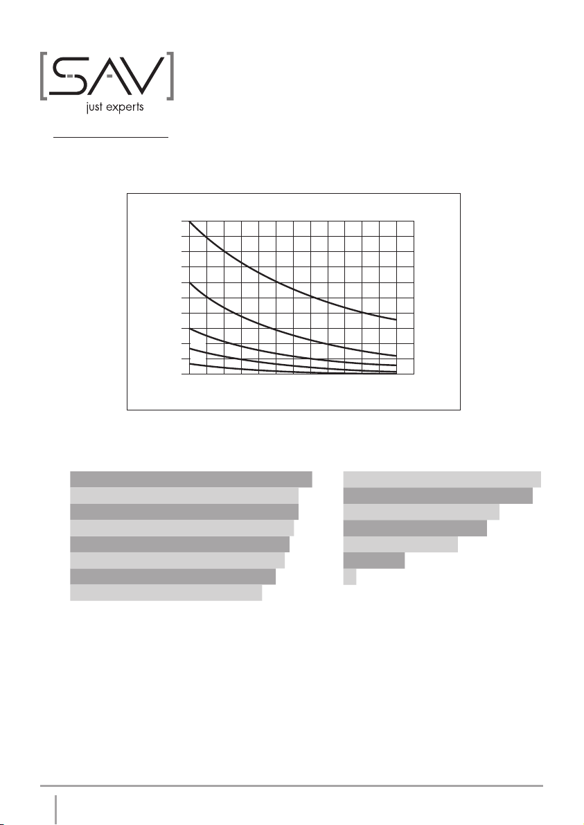
- Luftspalt zwischen Magnet und Werkstück durch Schmutz, Papier, Grate,
Beschädigungen, Farbe usw. (siehe Leistungsdiagramm auf Seite 8).
- Materialstärke der Last. Je dünner die Last, desto geringer die Tragkraft
(siehe Leistungstabelle auf Seite 7).
- Länge und Breite der Last. Die Tragfähigkeit wird durch die Blechgröße beeinflusst. Ein
Blech muss mindestens so lang sein wie der Magnet. Zu große Bleche hängen jedoch
durch, woraus sich ein Luftspalt zwischen Magnet und Blech ergibt. Dieser Abschäleffekt
senkt die Tragfähigkeit und begrenzt die maximale Blechgröße
- Materialzusammensetzung.Alle angegebenen Nennhaltekräfte beziehen sich auf St 37
mit 100 %. Sie reduzieren sich bei Stahlguss auf 90 %, bei V2A 430F auf 50 %, bei
Gusseisen auf 45 % und bei Nickel auf 10 % (siehe werkstoffabhängige Reduktions-
faktoren auf Seite 8). Für andere Materialien befragen Sie bitte den Lieferanten.
- Die Polflächen des Magneten müssen immer vollkommen durch das Werkstück bedeckt
sein.