Thank you for purchasing this light fitting.
Please read the instructions carefully before use to ensure safe and satisfactory operation of this product.
Please retain these instructions for future reference.
Existing fittings must be completely removed before installation of a new product. Before removing the existing
fitting, carefully note the position of each set of wires.
1. Undo the two screws on the end of the cover, pop the charging LED out of its holder, and the cover aside.
2. Cut a mounting hole in the ceiling taking care not to foul any pipes or mains cables beneath the surface.The hole
size should be 325mm x 115mm to fit the product into.
3. Ensure free movement of air around the fitting by removing any roof void insulation from at least 100mm
around the hole.
Under no circumstances must these fittings be covered with insulating matting or similar
material.
4. Using the side plate as a template, mark and drill the fixing holes.
5. Unscrew the 2 screws that hold the LED tray in place. Flip the tray up and wire into the terminal block as
detailed below.Then connect the battery.
You have correctly identified the wires.
The connections are tight.
No loose strands have been left out of the connection block.
Non Maintained LED’s are normally on and battery is on automatic charge (green charging LED is on) when the
mains supply is present. Fitting automatically switches the LED’s to emergency mode when the
supply is interrupted.
Maintained LED’s can be off or on as the unit can be switched separately and battery is on automatic charge
(green charging LED is on) when the mains supply is present. Fitting automatically switches the
LED’s to emergency mode when the permanant supply is interrupted.
1. Connect the unit to the mains (220-240V a.c.).Verify that the charging LED is illuminated; this confirms that
the batteries are charging.
2. The battery requires charging for at least 24 hours before first use.
3. When the unit is installed a green LED indicates that mains power is present and the battery is being charged.
4. If the charging LED is not illuminated then there may be no A.C. supply, the battery has not been connected
properly or the internal circuit may have failed.
5. The battery should be re-charged and checked every three months.
6. The battery should be discharged and the duration of the lamp in emergency mode checked every six months.
This is a Class 1 product and must be earthed.
Live Voltages may be present in this unit even when turned of or when completely disconnected.
Please read these instructions carefully before commencing any work.
This unit must be fitted by a competent and qualified electrician.
Install in accordance with IEE Wiring regulations and current Building Regulations.
To prevent electrocution switch off at mains supply before installing or maintaining this fitting. Ensure other persons
cannot restore the electrical supply without your knowledge.
This light fitting should be connected to a fused circuit.
If replacing an existing fitting, make a careful note of the connections.
This system contains non-replaceable parts and cannot be serviced. If damage occurs the part should be scrapped.
This product is not suitable for dimming.
Waste electrical products should not be disposed of with household waste. Please recycle where facilities exist.
Check with your local authority or retailer for recycling advice.
These products should not be fitted to PIR circuits or short duration timed switches.
Before cutting a mounting hole, ensure ceiling surface is flat to ensure a good fit.
This product is suitable for mounting in a suspended ceiling only.
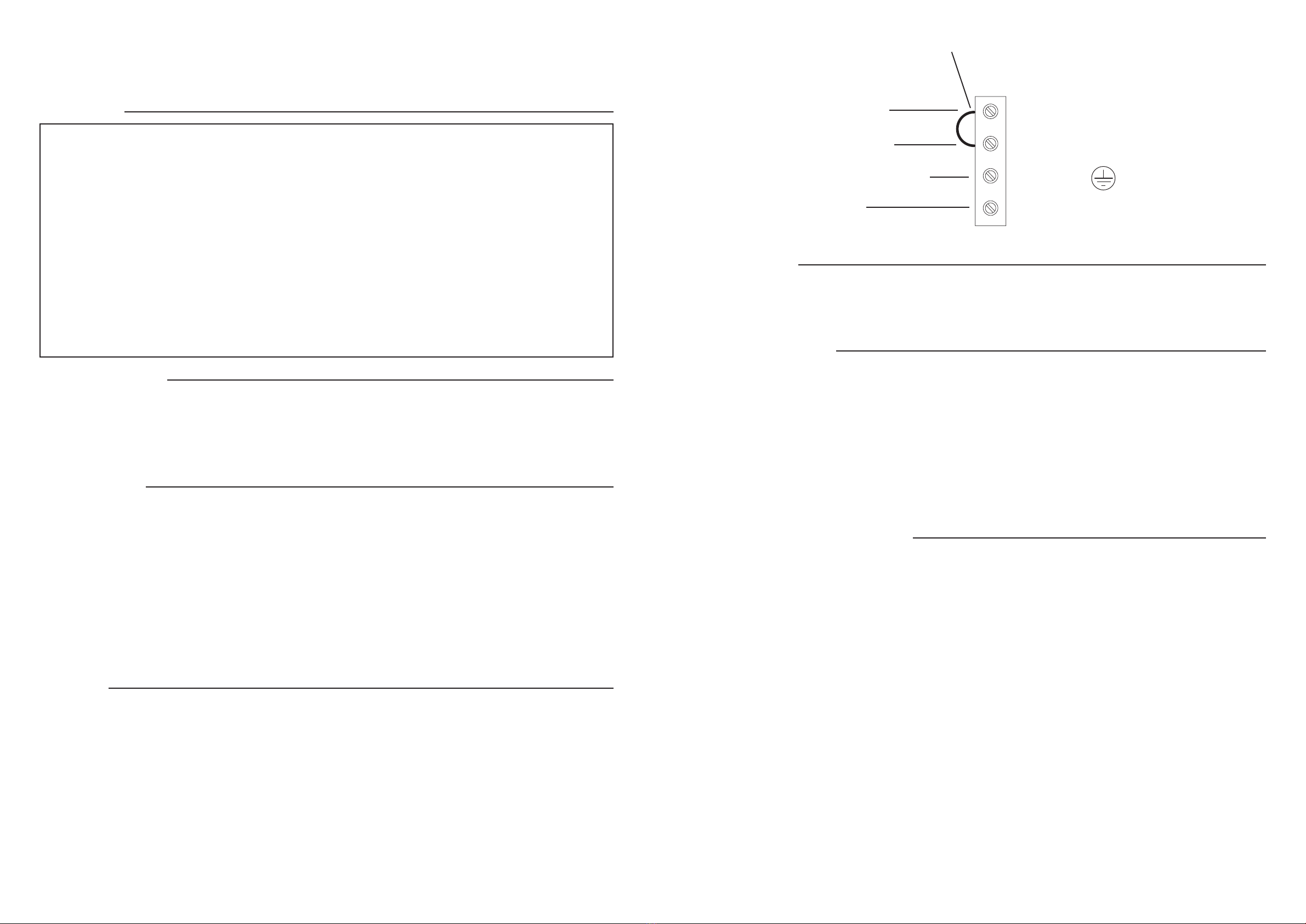
NEUTRAL TERMINAL
LIVE TERMINAL
EARTH TERMINAL
LIGHT FITTING
NEUTRAL
EARTH (GREEN/YELLOW)
PERMANENT LIVE
SWITCHED LIVE
SUPPLY
Warning
Power: 1.5W(15 LED’s)
Continuous Illumination: >3 hours
Battery: 3.6V 900mah
Recharge time: approximately 24 hours
Over-discharge Protection: Yes
Specification
Installation
Wiring
Check That
Operating Instructions
6. Push the unit up until firmly in position, ensuring that the cable is not trapped.
7. Adjust the cable so it does not get snagged.
8. Tighten the fixing bolts to secure the unit in place.
9. Fit the green exit sign. Refit the cover using the screws, taking care not to over tighten.
10. Replace fuse or circuit breaker and switch on.Your light is now ready for use.
Commisioning
This unit is capable of being wired in both Maintained and Non Maintained configurations.
Maintained Wiring:
To allow the unit to be switched separately, this link must be removed, and this terminal blocked connected to
the switched live.
Identify the permanent live and switched live and connect to the connection block inside the product in the
following way:
Non Maintained Wiring:
Leave in the link provided between the permanent live and the switched live to allow the LED’s to remain on.
Identify the permanent live and connect to the connection block inside the product in the following way:


