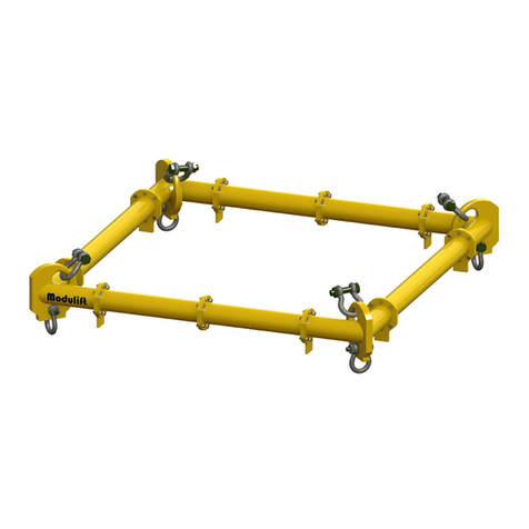
Modulift MOD 12 User manual

User Instructions
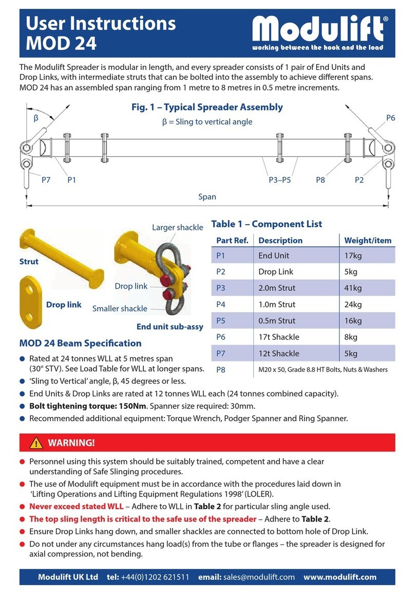
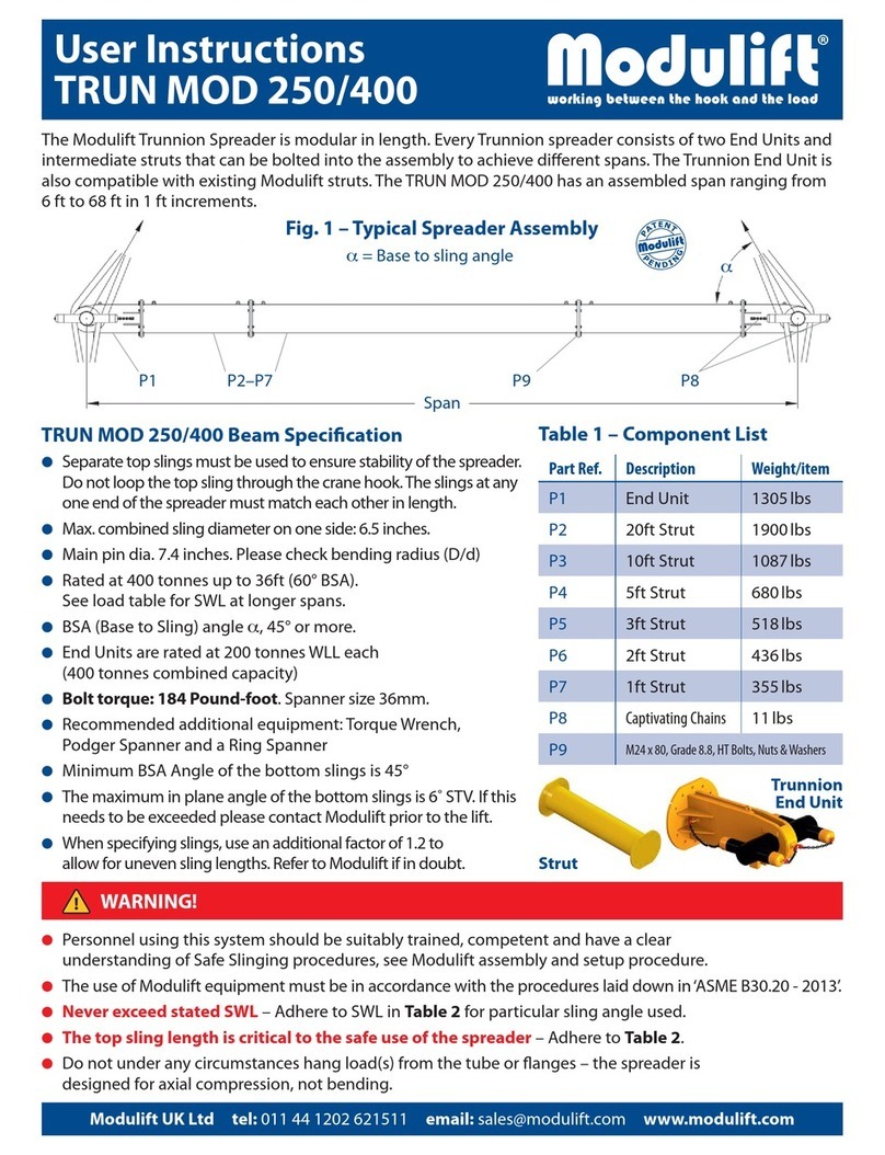
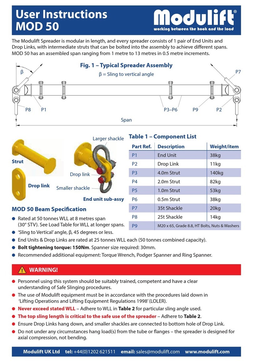
The Modulift Spreader is modular in length, and every spreader consists of 1 pair of End Units and
Drop Links, with intermediate struts that can be bolted into the assembly to achieve dierent spans.
Personnel using this system should be suitably trained, competent and have a clear
understanding of Safe Slinging procedures.
The use of Modulift equipment must be in accordance with the procedures laid down in
‘Lifting Operations and Lifting Equipment Regulations 1998’ (LOLER).
Never exceed stated WLL – Adhere to WLL in Table 2 for particular sling angle used.
The top sling length is critical to the safe use of the spreader – Adhere to Table 2.
Ensure Drop Links hang down, and smaller shackles are connected to bottom hole of Drop Link.
Do not under any circumstances hang load(s) from the tube or anges – the spreader is designed for
axial compression, not bending.
WARNING!
MOD 12
MOD 12 has an assembled span ranging from 0.5 metres to 6.5 metres in 0.25 metre increments.
MOD 12 Beam Specication
Rated at 12 tonnes WLL at 4.75 metres span
(30° STV). See Load Table for WLL at longer spans.
‘Sling to Vertical’ angle, β, 45 degrees or less.
End Units & Drop Links are rated at 6 tonnes WLL each (12 tonnes combined capacity).
Bolt tightening torque: 90Nm. Spanner size required: 19mm.
Recommended additional equipment: Torque Wrench, Podger Spanner and Ring Spanner.
P1 P2P3–P7
Span
βP8
P9 P10
β = Sling to vertical angle
Strut
Drop link
End unit sub-assy
Larger shackle
Smaller shackle
Drop link
Table 1 – Component List
Part Ref. Description Weight/item
P1 End Unit 6kg
P2 Drop Link 1.3kg
P3 1.5m Strut 19kg
P4 1.0m Strut 14kg
P5 0.75m Strut 11kg
P6 0.5m Strut 8kg
P7 0.25m Strut 6kg
P8 8.5t Shackle 2.5kg
P9 6.5t Shackle 1.5kg
P10 M12 x 35, Grade 8.8, HT Bolts, Nuts & Washers
Fig. 1 – Typical Spreader Assembly

User Instructions
Should you nd your equipment is no longer of use,
please dispose of in a responsible manner. Please
contact Modulift if you need further guidance
Do’s & Don’ts
Do ensure to load the spreader through the drop links
only. i.e. adhere to Fig. 1.
Do keep the loaded spreader clear of obstacles
– any contact could cause beam failure.
Do ensure correct use of appropriate top slings, do not
twist any slings unnecessarily.
Do not hang any load from the spreader tube or anges.
Do not exceed stated WLL for that particular span
– adhere to Table 2.
Do not rig the lower slings more than 6 degrees from vertical.
When moving or positioning long struts or assemblies use
tag lines to control movement.
Individual components can be heavy and extreme care
must be taken if manual handling.
Table 2 – Load v Span
Recommended top sling types:
Textile slings, wire rope slings with soft eyes and chain slings
with small end ttings. If thimble eyes are used with wire rope
slings, make sure sling angle is 30 degrees or less. Other types
exist but not all are suitable due to end tting size, particularly
larger capacity chain hook and thimble eyes.
Note: Lengthening the slings can give greater clearance.
Refer to Modulift supplier if in doubt.
The rigger must ensure that there is a clearance
between the sling end tting and the end unit
as shown above.
Max number of struts allowed in spreader
assembly: 5.
Assemble longer struts in the centre of the
spreader conguration.
Sling angle is crucial to safe use of spreader.
WARNING!
© Copyright 2019 Modulift.
All rights reserved.
Assembly Procedure
Check the ID plates on each Modulift component to
ensure the correct size is used.
Lay out the Struts and End Units in the correct
conguration (see Table 2), laid on ats to prevent rolling.
Check that all pairs of anges are clear from debris, sand
etc. before connection.
Bolt the components together using bolts, nuts & washers
provided. Tighten the bolts to a torque as shown overleaf,
4 bolts per connection. The number and grade of bolts
is critical for the safe use of the spreader particularly at
longer spans.
Place drop link inside the jaw of an end unit, with the
larger hole of drop link lined up with the End Unit hole.
Place a top sling onto the body of a top shackle, and put
jaw of top shackle over the end unit jaw.
Put top shackle pin through shackle, end unit jaw and
drop link, and repeat for other spreader beam end.
Attach free ends of top slings to crane hook.
Attach lower slings and shackles to lower holes of drop
links, and attach them to the load to be lifted.
The assembled spreader beam and lifting rig must be
thoroughly checked by a competent person prior to lifting.
MOD 12
MOD 12 UK JAN 2019
Span
(m)
Sling To Vertical Angle (STV) β
Recommended Conguration
EU - End Unit (0.25m)
45° 30° 20°
WLL
(t)
Min.top
sling
length
(m)
WLL
(t)
Min.top
sling
length
(m)
WLL
(t)
Min.top
sling
length
(m)
0.50 12 0.3 12 0.4 12 0.7 EU EU
0.75 12 0.5 12 0.7 12 1.0 EU 0.25 EU
1.00 12 0.6 12 0.9 12 1.4 EU 0.5 EU
1.25 12 0.8 12 1.2 12 1.8 EU 0.75 EU
1.50 12 1 12 1.4 12 2.1 EU 1 EU
1.75 12 1.2 12 1.7 12 2.5 EU 1 0.25 EU
2.00 12 1.4 12 1.9 12 2.9 EU 1.5 EU
2.25 12 1.5 12 2.2 12 3.2 EU 1.5 0.25 EU
2.50 12 1.7 12 2.4 12 3.6 EU 1.5 0.5 EU
2.75 12 1.9 12 2.7 12 4.0 EU 1.5 0.75 EU
3.00 12 2.1 12 2.9 12 4.3 EU 1.5 1 EU
3.25 12 2.2 12 3.2 12 4.7 EU 1 1.5 0.25 EU
3.50 12 2.4 12 3.4 12 5.1 EU 1 1.5 0.5 EU
3.75 11 2.6 12 3.7 12 5.4 EU 1 1.5 0.75 EU
4.00 10 2.8 12 3.9 12 5.8 EU 1 1.5 0.75 0.25 EU
4.25 9 2.9 12 4.2 12 6.2 EU 1.5 1 1 0.25 EU
4.50 8 3.1 12 4.4 12 6.5 EU 1.5 1 1 0.5 EU
4.75 7 3.3 12 4.7 12 6.9 EU 1.5 1 1 0.75 EU
5.00 6 3.5 11 4.9 12 7.3 EU 1.5 1 1 1 EU
5.25 5 3.7 10 5.2 12 7.6 EU 1.5 1 1 1 0.25 EU
5.50 5 3.8 9 5.4 12 8.0 EU 1.5 1.5 1 1 EU
5.75 4 4 8 5.7 12 8.3 EU 1.5 1 1 1 0.75 EU
6.00 4 4.2 7 5.9 12 8.7 EU 1.5 1 1 1 1 EU
6.25 4 4.4 7 6.2 11 9.1 EU 1.5 1.5 1.5 1 0.25 EU
6.50 3 4.5 6 6.4 10 9.4 EU 1.5 1.5 1 1 1 EU
Clearance Clearance

Supplementary User Instructions
1. Manufacturer’s Contact Details
Modulift UK Ltd
Cordite House, 4 Holton Point, Holton Heath
Trading Park, Poole, Dorset, BH16 6FL,
Website: www.modulift.com
2. Introduction
These supplementary instructions are an original
instruction in accordance with section 1.7.4
(Instructions and Annex II Declarations) of the EC
Machinery Directive 2006/42/EC, and are to be read
in conjunction with Modulift’s User Instructions
that accompany Generic products, and/or in
conjunction with the GA Drawing(s) issued for
job-specic custom designs.
3. EC declaration of conformity
With reference to the EC Declaration of Conformity
accompanying all new Modulift products, the
declaration is also referenced below:
We declare that the CE-marked products described
in these supplementary user instructions are in
compliance with the essential requirements and
full all the relevant provisions of the Directive
2006/42/EC, and as a minimum in conformance
with the following harmonized standards / applied
technical standards:
● BS EN 13155: 2003+A2:2009
● BS EN 1993-1-1: 2005
The products can be incorporated as part/s of
a CE-marked lifting assembly but must in that
case not be put into service until the nal lifting
assembly has been declared in conformity with the
provisions of the Directive 2006/42/EC.
Our management system complies with ISO
9001:2015 / ISO 14001: 2015 / ISO 45001: 2018 and
is certied by DNV – Business Assurance (Certicate
no. 176391-2015-AIMS-GBR-UKAS valid until 1st
April 2024)
If the products are modied without approval from
Modulift UK Ltd, this declaration becomes invalid,
and used at user’s own risk.
Poole, 12.05.20
Technical Representative: Sue Spencer
4. Markings
Modulift products have an engraved stainless steel
I.D. plate containing key information welded to
each component. However, there are some small
components that are not physically big enough
to have a plate welded to them, therefore the
key information is engraved directly onto the
component.
In accordance with the directive 2006/42/EC
section 1.7.3, all components are marked with:
● CE mark
● Modulift’s website address (contact details)
● Product name and/or size/designation
● WLL (note: for products that have varying WLL’s
depending on the assembled conguration, the
WLL is referenced in a table in the specic User
Instructions)
● Unique identication serial number
● Year of manufacture
● Self weight of component
Additional marking are permitted, provided that
it is applied using low stress punches on the I.D.
plates, or applied as labels.
5. Intended use
Modulift products are generally items used for
Lifting i.e. lifting accessories. These products
must only be used for their intended use, as
per the detailed User Instructions / GA Drawing
accompanying these products. For example, a
Spreader Beam designed for compression forces
must never be used as a Lifting Beam which is
designed for bending forces. Detailed technical
data and intended use can be found on the specic
User Instructions / GA Drawings specic to the
product.
Temperature rating of Modulift main generic
products: rated to -20°C to 60°C. Custom products
may dier, to be stated on certicate.
Fatigue: Fatigue failure can occur even if the

Supplementary User Instructions
WLL has not been exceeded. Scenarios in which
the product is subjected to variable load over a
prolonged period of time, will carry the risk of
inducing fatigue. Consider this when deciding
service intervals.
The rating of lifting accessories in European
Standards assumes the absence of exceptionally
hazardous conditions. Exceptionally hazardous
conditions include oshore activities, the lifting
of persons and lifting of potentially dangerous
loads such as molten metals, corrosive materials or
ssile materials. In such cases the degree of hazard
should be assessed by a competent person and the
working load limit adjusted accordingly.
6. Assembly
Generally, Modulift products are used as part of
a lifting rig used in lifting operations. Lifting rigs
tend to contain many dierent types of lifting
accessories interconnected.
Modulift are experts in designing and
manufacturing modular products, that need
assembly prior to use. Follow the User Instructions
regarding assembly, paying particular attention to
ensuring bolts, nuts & washers are tightened to the
required tightening torques.
Additional rigging accessories such as slings are
usually either connected directly to the Modulift
product, or via connection shackles and other
accessories. These additional rigging accessories
manufactured by other manufacturers will have
their own User Instructions and EC declarations,
refer to these specic instructions/declarations
and ensure these rigging accessories are properly
assembled & used.
7. User instructions
Modulift’s products must only be used after reading
and understanding the specic User Instruction(s).
8. Lifting: Planning and Operations
It is required by law that any company undertaking
a lifting operation must ensure it is planned and
carried out according to a safe system of work.
Requirements may vary from country to country,
but should as a minimum follow the following
guidelines:
All lifting operations must be planned by a suitably
trained and experienced competent person.
Planning a lifting operation should include:
● Risk Assessment – identifying all hazards and
mitigating the risk
● Method Statement – step-by-step guide for
onsite personnel to follow
● Determining complexity of lift rating
● Details of qualied personnel to be involved
in the lift e.g. slinger/signaller, lift supervisor,
riggers
● Detailed force calculations used to determine
correct sizing of lifting equipment being used in
the rig
● Details of sling lengths to ensure the hook is
directly over the CoG
● Sizing of slings to take into account oset CoG as
there will be higher forces on the heavy side
● Accuracy of weight and CoG position of the
items to be lifted – by calculation or weighing
● Safety factor applied to the weight of the skids
being lifted
● Stability calculation: the CoG is above the
connection points in the top skid – check for
toppling
● Site details, permissible oor loadings, access
etc.
● P.P.E. for all personnel
● Name of qualied AP (Appointed Person) that
has prepared the lift plan, and their contact
details in case of issues
All operators to follow safe sling procedures and
to be suitably trained and experienced, competent
persons. Operators must check equipment WLL for
the specic congurations against the plan / rig
drawing.
A competent person must check the rig prior to
commencing the lift. The path of the load that it
will be maneuvered through must be checked for
obstacles. The safety of other persons not involved
in the lift must be considered. Any deviations to the
planned lift must be discussed and agreed with the
person responsible planning the lift.

Supplementary User Instructions
Modulift UK Ltd are not responsible for planning
the lift and are not liable in any way for the advice
stated above.
9. Inspection prior to each use
The manufacturer’s EC Declarations of conformity
certicate must be found to be in order for all
equipment, and that the Modulift product(s) is/are
precisely as ordered.
Before each use the Modulift product(s) must be
inspected for obvious damage or deterioration.
The inspection should be done in accordance with
local regulations. If there is any doubt with regards
to these criteria being met, the product(s) must not
be used for a lifting operation. Modulift are able to
provide inspection guidance if required.
10. General instructions for safe use
General comments for lifting rigs:
● Do not exceed the stated WLL of the Modulift
product at the required conguration (see UI)
● - Do not exceed the WLL of the specic
connection point on the product, consider the
position of the CoG of the load being lifted
● - Top sling STV for spreaders must not be greater
than 45 degrees / greater than the specied STV
– top sling length is crucial.
● - Check the stability of the rig design – if the CoG
of the load is above its connection points – see
example opposite:
● Ensure that the rig is designed so that the CoG
of the item being lifted is directly below the
hook point, otherwise the rig will tilt and could
overload lifting equipment.
● - Ensure the load being lifted is strong enough to
be lifted in the proposed method.
● - All equipment within the rig must be of a
suitable capacity.
● - The rig should be checked by a competent
person prior to commencing lifting to ensure it is
correct as per the rig drawing, and everything is
securely fastened.
B
A
B >
A
B
A
B < A
B > A = Stable
B
A
B > A
B
A
B < A
B < A = Unstable
Top slings
Top slings
Spreader
Beam
Bottom
slings
Bottom
slings
The load
being lifted
The load
being lifted
Connection point
Connection point
Spreader
Beam
COG
position
COG
position

Supplementary User Instructions
11. Thorough examination
A thorough examination should be carried out by
a competent person at intervals not exceeding
six months, and at sooner intervals in accordance
with local laws or where the equipment is used in
extreme environments.
Components that have cracks, are visibly distorted
or twisted, severely corroded, or have gouges
in excess of 10% of the thickness of the material
should be discarded and replaced, or repaired. The
thorough examination should be carried out by a
competent inspector.
Fasteners should be inspected prior to each use,
and discarded if any visible damage to the bolt
shank or the thread.
12. Repair
Repairs must be done by Modulift if possible, but
in exceptional circumstances repairs can be done
by a third party in strict accordance with Modulift’s
requirements & express approval.
It is essential that Modulift is contacted to discuss
any repairs before proceeding, otherwise the
Modulift declaration becomes invalid.
13. End of life
Modulift products are generally made from
structural mild steel that can be widely recycled.
Table of contents
Other Modulift Lifting System manuals