SC&T Power Rack Series User manual

Smart Cabling & Transmission Corp. V1.0
V1.0
Converter Series
User Manual
Model : AD001HD4-4K
4K HD-TVI/ AHD/ HDCVI/ CVBS to HDMI/ VGA/ CVBS Converter
with Loop Out & Audio Embedder

1
User Manual
AD001HD4-4K
Introduction
AD001HD4-4K is a CCTV HD converter that supports up to 8MP video input for HD-TVI/ AHD/ HDCVI/ CVBS; it
allows surveillance video to be shown on 4K HDMI, VGA, and CVBS displays at the same time. If don’t have
a 4K TV, you can watch surveillance videos on an existing display. In addition, the converter has a 3.5mm
audio input to play the camera sound on an HDMI TV. It’s very suitable for grocery stores, train stations,
metro stations and public parking garages.
Features
Video input resolution up to 4K/ 8MP.
Video output resolution up to 4K for HDMI, 1080p for VGA, and NTSC/ PAL for CVBS.
Built-in loop out for daisy chain or a DVR.
Built-in 3.5mm audio input (Output through HDMI TV or external audio accepter).
Built-in RS232 Interface for RS232 commands or firmware upgrade.
Camera video displays on HDMI, VGA, CVBS displays at the same time.
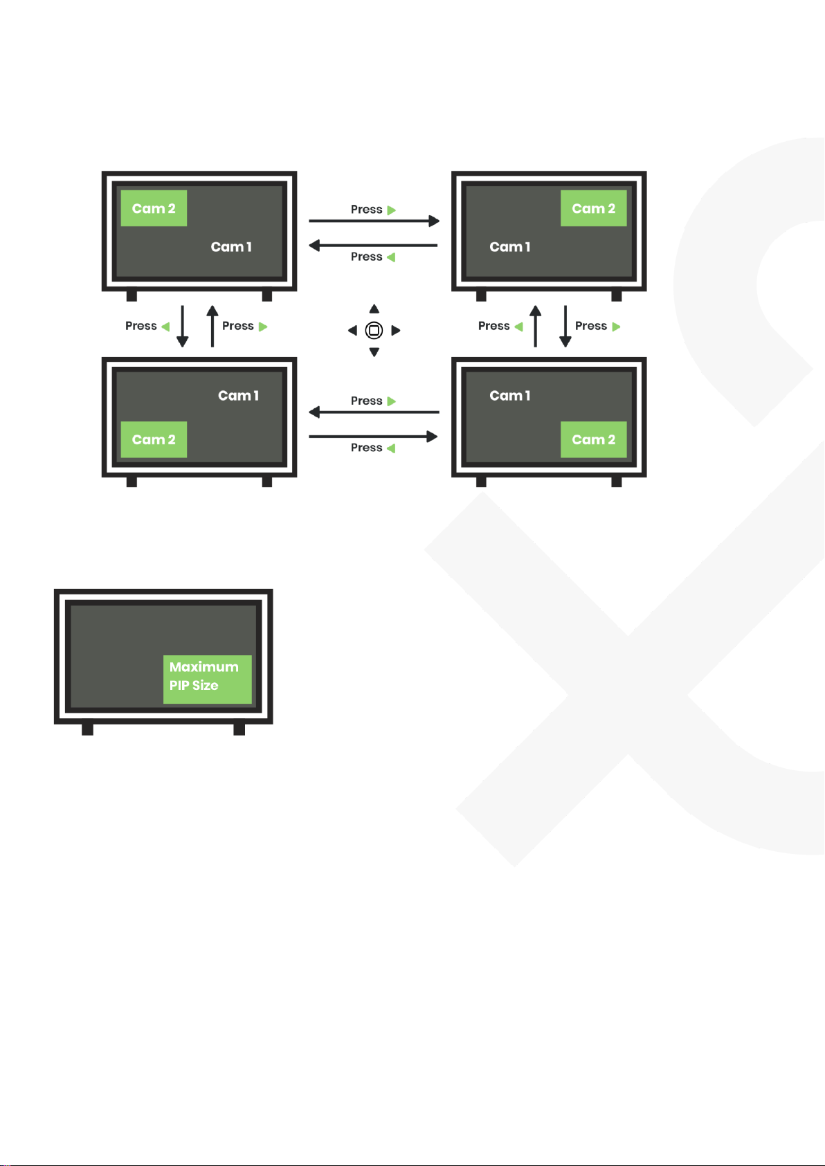
Supports PIP (Picture in Picture).
Support OSD (On Screen Display) to configure parameter.
UTC control commands may vary by camera brands, models, etc. So this function is not
available for all cameras.
Diagram
1 in 4 out Mode (HDMI, VGA, CVBS output at the same time)

2
User Manual
AD001HD4-4K
2 in 2 out Mode (Dual cameras with PIP)
2 in 3 out Mode (Dual cameras with manual switching Cam 1/ 2)

3
User Manual
AD001HD4-4K
Panel View
No
Interface
Function
1
Power LED
To indicate power status
2
Camera 1 LED
To indicate Camera 1 status
3
Camera 2 LED
To indicate Camera 2 status
4
OSD
To control OSD menu
5
Audio
To use a 3.5mm audio cable to connect an audio source from a
HD-TVI, AHD, HDCVI camera
6
Camera 1
To use a coaxial cable to connect with a HD-TVI, AHD, HDCVI
camera
7
Camera 2 / Loop Out
To use a coaxial cable to connect with a HD-TVI, AHD, HDCVI
camera, a DVR or another AD001HD4-4K
8
HDMI
To use an HDMI cable to connect with an HDMI display
9
VGA
To use a VGA cable to connect with a VGA display
10
CVBS
To use a coaxial cable to connect with a CVBS display
11
Console
To use a 3.5mm to RS232 cable to connect with a PC
12
DC 12V
To connect with a DC12V 500mA power adapter.

4
User Manual
AD001HD4-4K
LED Indication
Installation and Cabling
Avoid being in areas with electrical interferences, such as mobile phones, microwaves and so on,
when installing your AD001HD4-4K.
Remove the power before installation.
Audio Input
If connecting to a camera with a built-in microphone, AD001HD4-4K can only output the video
source.
Console
Use DB9(Female) to 3.5mm stereo phone jack.
Configure RS232 parameter at 115200/ 8-N-1.
Pinout Instructions:
3.5mm Stereo Phone Jack
PIN
Define
Pin 1
RX
Pin 2
TX
Pin 3
GND
Interface
LED Color
Status
Power
Green ON/ OFF
Power ON/ OFF
Camera 1
Green ON/ OFF
Signal Detected/ No Video
Camera 2
Green ON/ OFF
Signal Detected/ No Video
DB9 (Female)
PIN
Define
Pin 2
TX
Pin 3
RX
Pin 5
GND

5
User Manual
AD001HD4-4K
Video Format & Resolutions
Video Input Format & Resolutions (Auto Define HD-TVI, AHD, HDCVI, CVBS Video Format)
Resolutions
HD-TVI
AHD
HDCVI
8MP (4K)
12.5/15 FPS
15 FPS
15 FPS
6MP
X
X
20 FPS
5MP
12.5/20 FPS
20 FPS
X
4MP
25/30 FPS
25/30 FPS
25/30 FPS
2MP (1080p)
25/30 FPS
25/30 FPS
25/30 FPS
1.3MP (720p)
30 FPS
25/30 FPS
25/30/50/60 FPS
Video Output Format & Resolutions
Resolution
HDMI
VGA
CVBS
4K2K
30/ 25Hz
X
X
2160p
30/ 25Hz
X
X
1080p
60/ 50Hz
60/ 50Hz
X
1080i
60/ 50Hz
60/ 50Hz
X
720p
60/ 50Hz
60/ 50Hz
X
576p
60Hz
60Hz
PAL
480p
60Hz
60Hz
NTSC
When HDMI/ VGA resolution is set to
480p, 720p@60, 1080i@60, 1080p@60, 2160p@30, 4K2K@30, CVBS will be NTSC.
576p, 720p@50, 1080i@50, 1080p@50, 2160p@25, 4K2K@25, CVBS will be PAL.
OSD Settings
Use 5-Way Tactile Switch to Control OSD Menu
Button
Features
●
Turn ON/ OFF OSD menu
▲
Up
▼
Down
◀
Switch function
▶
Switch function

6
User Manual
AD001HD4-4K
Turn On OSD Menu
Press●and enter OSD menu.
Switch Modes
Press▲▼ to select Single Camera (Default) and pressto change modes
Supported Modes
1 in 4 out mode (with UTC pass through/ control)
2 in 3 out mode
2 in 2 out mode (with PIP)
Refer to the chart below to change modes:
Interface
1 in 4 out
2 in 3 out
2 in 2out (PIP)
Input
Cam 1
Up to 8MP
Up to 1080p
Up to 1080p
Cam 2
Loop out
(Resolution
same as Cam 1)
Up to 1080p
Up to 1080p
Output
HDMI
Up to 4K
Up to 4K
Up to 4K
VGA
Up to 1080p
Up to 1080p
Up to 1080p
CVBS
NTSC/PAL
NTSC/PAL
Not Supported
Caution
※The resolution of the two cameras must be at the range between 480p and 1080p. Otherwise, the
screen will display an OutRange reminder.
※VGA resolution only supports up to 1080p.
※Make sure your TV's supported resolutions when switching resolutions from AD001HD4-4K.
※Set up the same frame rate for both cameras when having dual camera inputs.

7
User Manual
AD001HD4-4K
Change Resolutions
Press▲▼to select “Resolution Out”, then pressto select a desired resolution
Refer to the chart below to switch the desired resolution:
Switching Order
Resolutions
1
480p
2
576P
3
720p@60Hz
4
720p@50Hz
5
1080p@60Hz
6
1080p@50Hz
7
2160p@30Hz
8
2160p@25Hz
9
4K2K@30Hz
10
4K2K@25Hz
11
1080i@60Hz
12
1080i@50Hz
Turn On UTC
In 1 in 4 out mode, press▲▼to select “UTC Control”and press, and then you can press
▲▼to control camera directions.

8
User Manual
AD001HD4-4K
Turn Off UTC
In the semi-transparent OSD menu, select “Back to OSD MENU”and pressto turn off UTC.
Change Video Source
In 2 in 2 out or 2 in 3 out modes, press▲▼to select “Source Select”and pressto choose Camera 1 or 2.
Turn on PIP
In 2 in 2 out mode, press▲▼to select “PIP Background”and pressto select Camera 1 or 2 as the
background.

9
User Manual
AD001HD4-4K
Change PIP Position
Press▲▼ to select “PIP Position”and then pressor to select position 1/ 2/ 3/ 4.
Adjust PIP Size
Press▲▼ to select “PIP Size”and pressor to enlarge/ reduce picture size (Max 1/4 TV size).
Perform Factory Reset
Step 1 -Press and hold ●when power off.
Step 2 -Power on, and press and hold ●for 5 secs until seeing Camera 1 and Camera 2/ Loop out
LEDs flashing.
Step 3 -Wait for the device to reboot.

10
User Manual
AD001HD4-4K
Factory Default
Default Mode
1 in 4 out Mode
Default Resolution
480p
Default Dual Video
Camera 1 [1]
Default PIP Background
Camera 1 [1]
Default PIP Position
Upper Right [2]
Default PIP Size
20%
Loop out for Daisy Chain
Refer to the chart below to configure 75Ωimpedance before daisy chain. Make sure to turn on 75Ω
impedance when not using daisy chain.
Daisy Chain Limit
Resolution
Cable Length
Daisy Chain Amount
1080p
100M
4 pcs
4K
100M
2 pcs
Daisy Chain Settings (Daisy chain 4 pcs of AD001HD4-4K as the example below)
Last AD001HD4-4K not connecting a DVR
Daisy Chain Amount
#1
#2
#3
#4
1
75ΩON
2
75ΩOFF
75ΩON
3
75ΩOFF
75ΩOFF
75ΩON
4
75ΩOFF
75ΩOFF
75ΩOFF
75ΩON
Last AD001HD4-4K connecting a DVR
Daisy Chain Amount
#1
#2
#3
#4
1
75ΩOFFDVR
2
75ΩOFF
75ΩOFFDVR
3
75ΩOFF
75ΩOFF
75ΩOFFDVR
4
75ΩOFF
75ΩOFF
75ΩOFF
75ΩOFF DVR

11
User Manual
AD001HD4-4K
Turn ON/ OFF 75ΩImpedance
Press▲▼ to select “Loop Out 75 ohm”and pressto turn ON/ OFF.
Caution
※Turn ON 75Ωimpedance when AD001HD4-4K is not connected to a DVR; otherwise, turn OFF 75Ω
impedance when connected with a DVR.
※You can only configure 75Ωimpedance in 1 in 4 out mode. In other modes, it will turn ON the 75Ω
impedance automatically.
※When using daisy chain, AD001HD4-4K won’t support audio input for camera.
RS232 Commands
Commands
Functions
RESET
Perform Factory Reset
VERSION
Show Firmware Version
W
OSD ▲
A
OSD ▼
S
OSD
D
OSD
E
OSD ●Turn ON/ OFF
I
UTC ▲
K
UTC ▼
J
UTC
L
UTC
O
UTC ●Turn ON/ OFF
DEFAULT
Perform Factory Reset
HELP
Show All Commands
?

12
User Manual
AD001HD4-4K
Package
Item
Amount
AD001HD4-4K
1 pc
DC 12V 500mA Power Adapter
1 pc
SMT Self-tapping Screw
4 pcs
Wall Plug
4 pcs
Rubber Pad
4 pcs

13
User Manual
AD001HD4-4K
Specification
Item No
AD001HD4-4K
Support
Video Format
HD-TVI, AHD, HDCVI, HDMI, VGA, CVBS
Video Input Resolution
8MP@12/15Hz
HDMI Resolution
480p、576p、720p/50/60、1080p/50/60、2160p/25/30、4K2K/25/30、
1080i/50/60
VGA Resolution
480p、576p、720p@50/60、1080p@50/60、1080i@50/60
CVBS Resolution
NTSC、PAL
Ports & Interfaces
Video Input
1 x 75ΩBNC (1Vpp)
Video Output
1 x HDMI Type A, 1 x VGA (D-SUB 15), 1 x 75ΩBNC (1Vpp)
Video Loop out
1 x 75ΩBNC (1Vpp)
Audio Input
1 x (3.5mm) Phone Jack
Console (RS232)
1 x (3.5mm) Phone Jack
Power
Power Supply
DC 12V 500mA
Power Consumption
320mA
Ambient Temperature
Operation
0 to 70℃
Storage
-40 to 125℃
Humidity
up to 90%
Physical Characteristics
Dimension
125 x 130 x 30mm
Weigh
370g

14
User Manual
AD001HD4-4K
Installation Guide
Item
A
Wall Plug
x4
B
SMT Self-tapping Screw
x4
C
Rubber Pad
x4
Install On A Table Or A Wall
Step 1: Evenly fix SMT screws on a platform and leave a 2mm high clearance.

15
User Manual
AD001HD4-4K
Step 2: Place AD001HD4-4K on the platform and fit its holes in the corresponding screw positions.
Step 3: Move AD001HD4-4K until it gets fixed.

16
User Manual
AD001HD4-4K
Use Rubber Pads to Prevent the Product from Slipping down The Platform
Fix each rubber pad at each corner of the product.
Other manuals for Power Rack Series
2
This manual suits for next models
1
Table of contents
Other SC&T Media Converter manuals

SC&T
SC&T AD001HDE User manual

SC&T
SC&T C D102HD User manual

SC&T
SC&T Data Transmission Series User manual

SC&T
SC&T AD001TVI User manual

SC&T
SC&T HD401F4-5M User manual

SC&T
SC&T CD104HD User manual

SC&T
SC&T CD408HD User manual

SC&T
SC&T AD001HD4 User manual

SC&T
SC&T HVY01 User manual

SC&T
SC&T AD001HD4 User manual
Popular Media Converter manuals by other brands

Thor Broadcast
Thor Broadcast H-12HDMI-QAM-IPLL user manual

Vdwall
Vdwall LVP user manual

Blackmagicdesign
Blackmagicdesign Broadcast Converter Operation manual

Four Audio
Four Audio HD2 manual

PCB Piezotronics
PCB Piezotronics 422E53 Installation and operating manual

Marshall Electronics
Marshall Electronics VS-104D-3GSDI user manual