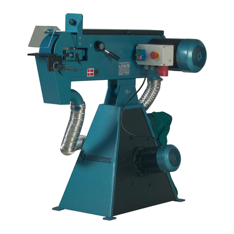
Scantool 1220 User manual

SCANTOOL 1220
ENG Instruction manual for bench belt grinder
DE Bedienungsanleitung für Tisch Bandschleifmaschinen
DK Brugsanvisning: Værkstedsbåndsliber, bænkmodel

READ THIS MANUAL BEFORE USE
DIESE ANLEITUNG VOR DER VERWENDUNG LESEN
LÆS DENNE MANUAL FØR ANVENDELSE

DECALAIRATION OF CONFORMITY
We hereby declare that the concept and manufacturing of the machine mentioned below meets all safety and health
prescriptions according mentioned below EU regulations. In case of technical modifications without permission this
declaration is void.
MANUFACTURER:
SCANTOOL A/S
Industrivej 3-9
9640 Brovst
DESCRIPTION & IDENTIFICATION OF THE MACHINE:
600711220 Beltgrinder SC 1220
EC DECLARATION OF CONFORMITY:
Low Voltage regulation (2014/35 / EU of 26 February 2014)
EMC 2014/30 / EU of 26 February 2014
RESPONSIBLE FOR THIS TECHNICAL DOCUMENTATION:
Director
Claus Nielsen

EG KONFORMITÄTSERKLÄRUNG
Hiermit erklären wir, dass die nachfolgend beschriebene Maschine in Konstruktion und Ausführung sowie in der von uns
vertriebenen Version den grundlegenden Sicherheits- und Gesundheitsanforderungen entspricht, siehe die nachfolgend
beschriebenen Richtlinien.
Bei einer mit uns nicht abgestimmten Änderung der Maschine verliert diese Erklärung ihre Gültigkeit.
MANUFACTURER:
SCANTOOL A/S
Industrivej 3-9
9640 Brovst
BESCHREIBUNG UND IDENTIFIKATION DER MASCHINE:
600711220 SC 1220
EG KONFORMITÄTSERKÄRUNG:
Niederspannungsrichtlinie 2014/35 / EU of 26 February 2014
EMC 2014/30 / EU of 26 February 2014
VEVOLLMÄCHTIGER FÜR DIE TECHNISCHE DOKUMENTATION:
Direktor
Claus Nielsen

EU OVERENSSTEMMELSESERKLÆRING
Vi erklærer hermed, at den nedenfor beskrevne maskine, opfylder alle væsentlige sikkerheds- og
sundhedsbestemmelser, jf. nedenstående EU-regulativer.
I tilfælde af, at der foretages tekniske ændringer på produktet, der ikke aftalt med os, vil denne erklæring være ugyldig.
PRODUCENT:
SCANTOOL A/S
Industrivej 3-9
9640 Brovst
BESKRIVELSE & IDENTIFIKATION AF MASKINEN:
600711220 SC 1220
EU OVERENSSTEMMELSESERKLÆRING:
Lavspændingsdirektivet 2014/35 / EU of 26 februar 2014
EMC 2014/30 / EU of 26 februar 2014
ANSVARLIG FOR DEN TEKSNISKE DOKUMENTATION:
Direktor
Claus Nielsen

1
INDEX
ENGLISH
SAFETY RULES FOR ALL POWER TOOLS ................................................................................................................1
TECHNICAL DATA .............................................................................................................................................................2
UNPACKING AND CHECKING LIST..................................................................................................................................3
ASSEMBLY OF FITTINGS ................................................................................................................................................. 4
ADJUSTMENT OF THE SANDING BELT........................................................................................................................5
REPLACEMENT OF BELT .................................................................................................................................................6
REPLACEMENT OF PRIME WHEEL .................................................................................................................................7
EXAMPLE OF OPERATING...............................................................................................................................................8
PART LIST........................................................................................................................................................................10
ELECTRICAL CONNECTION/DISCONNECTION & OPERATION ..................................................................................11
WARRANTY......................................................................................................................................................................14
DEUTSCH
SICHERHEITSVORSCHRIFTEN FÜR ALLE ELEKTROWERKZEUGE...........................................................................15
AUSPACKEN UND CHECKLISTE....................................................................................................................................18
MONTAGE DER ANBAUTEN...........................................................................................................................................19
ANPASSEN DES SCHLEIFBANDS..................................................................................................................................20
AUSTAUSCH DES BANDS ..............................................................................................................................................21
WICHTIGER HINWEIS FÜR CE.......................................................................................................................................21
AUSTAUSCH DES HAUPTRADS.....................................................................................................................................22
BETRIEBSBEISPIEL ........................................................................................................................................................23
DIAGRAMM ......................................................................................................................................................................24
TEILELISTE......................................................................................................................................................................25
ELEKTRISCHE/R ANSCHLUSS/TRENNUNG & BETRIEB..............................................................................................26
ELEKTRISCHER SCALTPLAN.........................................................................................................................................27
TEILELISTE ELECTRISCHER KOMPONENTEN ............................................................................................................28
GARANTIE........................................................................................................................................................................29

2
DANSK
SIKKERHEDSREGLER FOR ALLE ELEKTRISKE VÆRKTØJER ...................................................................................30
TEKNISKE DATA................................................................................................................................................................ 2
UDPAKNING OG TJEKLISTE.............................................................................................................................................3
MONTERING AF MASKINEN.............................................................................................................................................4
JUSTERING AF SLIBEBÅND .............................................................................................................................................5
UDSKIFTNING AF BÅNDET...............................................................................................................................................6
VIGTIG INFORMATION I FORHOLD TIL CE-ERLÆRINGEN............................................................................................6
UDSKIFTNING AF DRIVHJUL............................................................................................................................................7
EKSEMPELER PÅ SLIBNING ............................................................................................................................................8
DIAGRAM ...........................................................................................................................................................................9
STYKLISTE.......................................................................................................................................................................10
ELEKTRISK TILSLUTNING/FRAKOBLING OG BETJENING ..........................................................................................11
ELEKTRISK KREDSKØBSDIAGRAM ..............................................................................................................................12
LISTE OVER ELEKTRISKE KOMPONENTER.................................................................................................................13
GARANTI ..........................................................................................................................................................................14

ENG
1
SAFETY RULES FOR ALL POWER TOOLS
1. Read and become familiar with the entire instruction
manual. Learn the tool’s applications. limitations and
possible hazards.
2. Earth all tools. If the tool is equipped with a three-
prong plug, it must be plugged into a three-contact
electric outlet. The third prong is a ground to
provide protection against accidental electrical
shock. If an adapter is used to accommodate a two-
contact outlet, the adaptor’s grounding lug must be
connected to a known ground. Never remove the
third prong on a three- prong plug.
3. Check damaged parts. A guard orany other part
that is damaged should be checked to ensure that it
will operate properly and perform its intended
function before the tool is used further.
Check for proper alignment of moving parts and for
possible broken parts, loose mountings, or any
other condition that could affect the tool’s operation.
A guard or other damaged part should be properly
re- paired or replaced.
4. Disconnect power before servicing and when
changing accessories such as blades, cutters.
5. Keep guards in place and in working order.
6. Protect your eyes from being injured by objects
thrown by a power tool. Always wear safety
glasses orsafety goggles.
7. Wear a face mask or dust mask if the cutting
operation produces dust.
8. Don’t force the tool. It will give a better and safer
performance when used on jobs for which it was
de- signed.
9. Avoid accidental starting. Ensure that the power
switch is in the OFF position before plugging in the
power cord.’ Remove the switch when the tool is
not being used.
10. Remove adjusting keys and wrenches.
Ensure that keys and adjusting wrenches are
removed from the tool before turning it on.
11. Drugs, alcohol, and medication. Do not operate tool
if you are under the influence of drugs, alcohol, or
medication that could affect your ability to use the
tool properly.
12. Use recommended accessories. Using improper
accessories can be hazardous. If in doubt, check the
instruction manual.
13. Never stand on a tool. Falls can result in
injury.
14. Never leave a tool running unattended. Turn the
power switch OFF. Don’t leave the tool until it has
come to a complete stop.
15. A1ways remove the power cord plug from the electric
outlet when adjusting, changing parts, cleaning, or
working on the tool.
16. Avoid dangerous conditions. Don’t use power tools in
wet or damp areas or expose them to rain. Keep your
work area clean and well lighted. Do not use power
tools in areas where fumes from paint,
solvents, or flammable liquids pose a potential hazard.
17. Keep visitors and children away.
Other people should keep a safe distance from the work
area, especially when the tool is operating.
18. Use the proper tool. Don’t force a tool to do a job for
which it was not de- signed.
19. Keep tools in top condition. Keep them clean and sharp
for the best and safest performance. Follow the
instructions for changing accessories and lubricating.
20. Secure all work. When practical use clamps or a vise to
hold work. It is safer than using your hands and pre-
vents round or odd-shaped pieces from turning.
21. Don’t overreach. Keep proper footing and balance
always. Wear oil- resistant rubber-soled footwear.Keep
the floor clear of oil, scrap wood, and other debris.
22. Wear proper clothing and, if necessary, protective hair
covering. Loose clothing or jewelry can get caught in
moving parts.
23. Make the workshop childproof with padlocks, master
switches, or by removing starter keys.

ENG
2
TECHNICAL DATA
MODEL
SCANTOOL 1220
Motor (kw Output)
Phase
Sanding Belt (mm)
Belt Speed
Driving Wheel (mm)
Flat Grindlng Surface (mm)
Dimensions (mm L x W x H)
Machine Height (mm W/Stand)
Net Weight (kgs)
Stand (mm L x W x H)
0.75
1 Ph/230 V
100 x 1220
19m / sec
Ø 126 x 100mm 320 x 100mm
650 x 380 x 260
1070
26.5
380 x 395 x 810

ENG
3
Main Body
4 Sanding Stop Plate & Tool
①Sanding Stop Plate
②6mm Hex. Wrench
①③12mm Open Spanner
④Socket Wrench
④
②③
1
5
5
33
Ref.
No.
Parts/ Description Name
Q’ty
1
2
3
4
5
6
7
8
Eye Shield
Support Plate
Hex. Bolt M6x45L Spring
Washer M4
Hex. Nut Looseproof M6 Screw
M4x10L
Washer M4 Hex.
Nut M4
1
1
1
2
1
2
2
2
3 Eye Shield Assembly
5 Dust Collector
1
Main Body
2 Working Table
UNPACKING AND CHECKING LIST

ENG
4
1
The Set Up of Sanding Stop Plate
●Push down the belt tension lever to gain tension.
The belt tension was totally released be- fore
delivery ex works.
●Install the sanding stop plate and make sure it
does not touch the sanding belt.
2
The Set Up of Working Table
Put working table at correct position and keep
proper distance to the sanding belt.
3
The Set Up of Dust Collector
Fix dust collector unit by using two screws on each
side. Read page 8 for more information.
4
The Set Up of Eye Shield
Install the eyeshield to the machine and make
necessary adjustment to gain the maximum
protection. Read page 8 (exploded view) for more
information.
5
The Adjustment of Eye Shield
5
4
3
A 3mm distance between
working table and sand-
ing belt is required.
2
A safety distance between the
sanding stop plate and sanding
belt.
Sanding stop plate touches
sanding belt.
1
ASSEMBLY OF FITTINGS

ENG
5
Belt Tracking Adjustment
1. Plug into an
electrical inlet on
machine body before
connecting with the
power supply.
2. Turn tracking knob clockwise
to make sanding belt toward
left side or turn counter-clockwise to make belt toward right side. Note: It is only allowed a tiny adjustment at
each turn.
3. Rotate belt by hand, meanwhile adjust tracking knob.
4. Control the switch for a short on/off starting with left hand, meanwhile put right hand on tracking knob for
clockwise or counter turning till the belt runs stably between the two rollers.
Belt Tension Adjustment
Be sure the switch is on OFF position. Measure the belt tension
from the bottom by thumb press. The tension was always well
adjusted before delivery ex works. The adjustment is required
when belt was used for a period and get loosed or when
renewing the belt.
The Procedure for Belt Tension Adjustment.
1. Open the steel cover.
2. Turn the belt tension lever clockwise about 120° to
release the tension.
3. The hex. nut is designed to hold the adjusting rod in
position against the vibration during operation. This nut
needs to be loosened before making adjustment and
tightened after adjustment.
If the belt tension is too low.
4.Turn adjusting rod (part No. 14) upward to gain
tension. If the belt tension is too high. Turn adjusting rod
(parts No. 14) downward to release tension.
5.Tips for adjustment.
Each turning of adjusting rod makes rubber roller
outward
(of inward) about 2.5mm. A' micro adjustment, 0.42mm
for each phase turning of adjusting rod, is
recommended.
6. Close the steel cover and push down the belt tension
lever.
7. After this adjustment, try with Tracking Adjustment.
ADJUSTMENT OF THE SANDING BELT

ENG
6
REPLACEMENT OF BELT
1.Pull belt tension lever upward.
2.Remove two screws, open the protection cover and
remove the used belt.
3.Locate the new belt on two rollers.
4.Push belt tension lever downward.
5.Rotate belt by hand, meanwhile adjust tracking knob as
a pretest before power test.
6.Locate protection cover then use left hand to control the
switch with a short on/off starting, meanwhile put right
hand on tracking knob for clockwise or counter turning
till the belt runs stably between the two rollers.
7.Check belt tension. If the tension is improper for
working, then begin the adjustment procedures (see
page 4) until the tension is satisfactory.
8.Repeat the procedures of hand test and power test for
belt runs stably between the two rollers.
IMPORTANT NOTICE FOR CE
Handling of Machine
1.The total weight of this machine must be ensured before handling. 2.It is better to handle this machine with the help of
lifting tools.
Environment Requirements for Installation.
1.Be sure to provide sufficient light for operation according to the codes or regulations published for local area. If you do
not get the information about lighting, a light intensity of 300 Lux is the least value to be supplied.
2.The place where machine install must be flat and big enough for the operation.
Noise Level
1.The noise level of this machine is about 75 db(A) during operation.
2.While taking provisions for the risk of noise, the noise level of working environment should be taken into
consideration also.

ENG
7
REPLACEMENT OF PRIME WHEEL
1. Pull belt tension lever upward.
Take off the movable cover and open the protection cover
by remove five screws, then re- move the belt.
2. Remove the motor rear cover by remove two screws.
Use screwdriver or steel bar to insert the hole at the end
of motor shaft, then hold the bar tighten and keep motor
shaft steady.
3. Use provided deep socket to plug into the nut at the
other end of motor shaft.
Turn screw- driver and socket wrench at reversed
direction, this will loosen the nut of roller.
4. Take off the nut, used prime (aluminium)
roller is removed. Reload the new prime roller.

ENG
8
EXAMPLE OF OPERATING
Example 1:
Roller sanding
Hold workpiece firmly by hand and use working table
as support for roller sanding.
Example 2:
Surface sanding
Take off movable cover. Place workpiece on the top of
belt for sanding of large surface.
Example 3:
Sanding job is creating dust of all kinds which pollutes
your working room. This machine pro- vides a dust
collector and chute of Ø 35mm. Use your own
connector and hose to link with dust collecting system
to ensure the best comfortable working environment.

ENG
9
DIAGRAM

ENG
10
PART LIST
Ref.No.
Part Name
Ref. No.
Part Name
Ref. No.
Part Name
1
Hex. Bolt
47
Cover
90
Packing
2
Screw
48
Tracking Knob
91
3
Spring Washer
49
Spring
92
Wirig Box
4
Dust Proof Cover
50
Washer
93
5
Base
51
Cap Screw
94
6
Hex. Bolt
52
Washer
95
Packing
7
Bush
53
Working Table
96
Screw
8
Dust Proof Plate
54
Sanding Stop Plate
97
9
Belt Support
55
Wing Nut
98
10
Arrow Mark
56
Support Plate
99
*Strain Relief
11
Cam
57
Screw Shaft
100
Screw
12
Hex Nut-Looseproof
58
101
Hex. Bolt
13
Press Block
59
Hex. Bolt
102
Hinge A
14
Adjusting Rod
60
Dust Collector
103
Hinge B
15
Hex. Nut
61
Eye Shield
104
Hinge C
16
Sliding Block
62
Washer
105
Washer
17
Pin
63
Hex. Nut
106
Toothed Washers
18
Adjusting Block
64
Screw
107
Screws
19
Spring
65
Rear Protector
108
Washer
20
Spring Stop Plate
66
Fan
109
Nuts
21
Upper Support
67
Rear Support
110
Shock Pad
22
Cap Screw
68
Ball Bearing
111
Screws
23
Block Stop. Plate
69
Rotor
24
Lower Support
70
Stator Housing
25
Moveable Cover
71
Ball Bearing
26
Aluminum Roller
72
Front Support
27
Hex. Nut
73
Screw
28
Rubber Roller
74
Plum Screw
29
Snap Ring
75
Switch
30
Ball Bearing
76
31
Bush
77
32
Graphite Packing
78
Supporting Plate
33
Snap Ring
79
Screw
34
Sanding Belt
80
Strain Relief
35
Washer
81
Power Cord
36
Hex. Shaft
82
Wiring Box Cover
37
Protection Cover
83
Packing
38
Hex. Bolt
84
Screw
39
Ball Knob
*85
Capacitor Sleeve
40
Screw Shaft
*86
Running Capacitor
41
Cam Shaft
*87
Capacitor Cover
42
Loosen-Tighten Plate
88
Plug
43
Adjusting Plate
89
Plug Socket
44
Cover Screw
45
Wave Washer
46
Cover Plate

ENG
11
ELECTRICAL CONNECTION/DISCONNECTION & OPERATION
-FOR SINGLE PHASE.
1. The connection, disconnection, and grounding is carried out through the plug, equipped on the sander. For the
safety reason
Do not change this plug into any the other type in any situation.
2. For the protection of control device, we recommend the Operator to supply a fuse with 10A current rating of fuse,
and the total length between fuse and connection terminal shall not exceed 1.5 m.
3. The exact power source voltage, frequency, and number of phase shall be checked according to the installation
diagram and circuit diagram.
Ensure that the power switch is in OFF position before electrical connection and disconnection.
OPERATION.
1. "START": Push the button marked with "I".
2. "STOP": Push the button marked with "O".
MAINTENANCE:
1. Be sure to disconnect the sander from power source.
2. If motor being overload, the overload relay will be active. If you want to reset sander, open control enclosure and then
push the reset button of overload relay.

ENG
12
ELECTRICAL CIRCUIT DIAGRAM

ENG
13
S
V
CSA UL
D E
CEBEC D FI N S V öve
D E
CEBEC D FI N S V öve S
D E
ELECTRICAL COMPONENTS PART LIST
Item Designation
Designation & Function
Technical Data
Remark
D.O.L. starter
IP 54
VDE 0660
IEC 947
KM
Magnetic contactor
600 Vac, 20A
FR
Overload relay for single phase
SB
push button for OFF
SB2
push button for ON
XS
Socket for single phase
250 Vac, 15A
XP1
XP2
Plug for single phase
250 Vac, 16A
250 Vac, 10A
Kabel für 1~
H05VV-F, 3 x
1,0mm2
Table of contents
Languages:
Other Scantool Grinder manuals